light ISUZU TFS SERIES 1997 User Guide
[x] Cancel search | Manufacturer: ISUZU, Model Year: 1997, Model line: TFS SERIES, Model: ISUZU TFS SERIES 1997Pages: 1600, PDF Size: 40.98 MB
Page 481 of 1600

CAB 10-27
Important Operations
1. Center Console Assembly
Remove shift knob and 2 fixing screws (front side).
Open the grommet and remove 2 fixing screws (rear
side).
2. ECM cover
3. Glove Box
Remove 2 fixing screws and pulling the handle.
4. Glove Box Cover
Remove 4 fixing screws and pull the cover toward you
and remove the clips at 2 positions.
5. Instrument Panel Passenger Lower Cover Assembly
Remove 3 fixing screws and 1 clip.
6. Instrument Panel Driver Lower Cover Assembly
Remove the engine hood opener 2 fixing screws and 6
fixing screws.
Disconnect the connector of the illumination.
7. Lower Cluster Assembly
Remove 3 fixing clips.
8. Meter Cluster Assembly
Remove 3 fixing screws, 7 clips and switch connectors.
9. Instrument Panel Lower Center Cover Assembly
Remove 7 fixing screws and disconnect the connector of
the cigarette lighter.
Page 488 of 1600

10-34 CAB
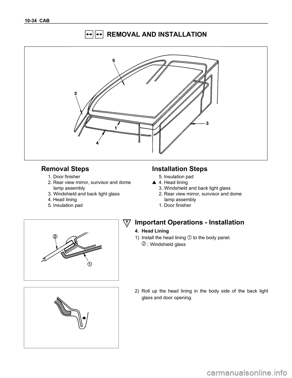
REMOVAL AND INSTALLATION
Removal Steps
1. Door finisher
2. Rear view mirror, sunvisor and dome
lamp assembly
3. Windshield and back light glass
4. Head lining
5. Insulation pad
Installation Steps
5. Insulation pad
4. Head lining
3. Windshield and back light glass
2. Rear view mirror, sunvisor and dome
lamp assembly
1. Door finisher
Important Operations - Installation
4. Head Lining
1) Install the head lining
1 to the body panel.
2 : Windshield glass
2) Roll up the head lining in the body side of the back light
glass and door opening.
Page 498 of 1600

CAB 10-1
SECTION 10
CAB
TABLE OF CONTENTS
PAGE
Servicing<0011001100110011001100110011001100110011001100110011001100110011001100110011001100110011001100110011001100110011001100110011001100110011001100110011001100110011001100110011001100110011001100110011001100
11001100110011[<0011001100110011001100110011001100110011001100110011001100110011001100110011001100110011001100110011001100110011001100110011001100110011001100110011001100110011001100110011001100110011001100110011001100
11001100110011001100110011001100110011001100110011[........ 10- 2
Windshield and Back Light Glasses ................................................................................ 10- 3
Sliding Rear Window Assembly ....................................................................................... 10- 8
Doors .................................................................................................................................. 10- 12
Instrument Panel...............................................<0011001100110011001100110011001100110011001100110011001100110011001100110011001100110011001100110011001100110011001100110011001100110011001100110011001100110011001100110011001100110011001100110011001100
11001100110011001100110011001100110011001100110011[.. 10- 26
Console Box ....................................................................................................................... 10- 31
Head Lining ........................................................................................................................ 10- 33
Quarter Glass (Space Cab) ............................................................................................... 10- 36
Front Seat ........................................................................................................................... 10- 37
Front and Rear Seat Belt ................................................................................................... 10-39
<002d005800500053000300360048004400570011001100110011001100110011001100110011001100110011001100110011001100110011001100110011001100110011001100110011001100110011001100110011001100110011001100110011001100
11001100110011001100110011001100110011001100110011[<0011001100110011001100110011001100110011001100110011001100110011001100110011001100110011001100110011001100110011001100110011001100110011001100110011001100110011001100110011001100110011001100110011001100
11001100110011001100110011001100110011001100110011[...... 10- 40
Jump Seat Belt .................................................<0011001100110011001100110011001100110011001100110011001100110011001100110011001100110011001100110011001100110011001100110011001100110011001100110011001100110011001100110011001100110011001100110011001100
11001100110011001100110011001100110011001100110011[... 10- 41
INDEX
Page 499 of 1600

10-2 CAB
SERVICING
Engine Hood Lock
Align the engine hood lock with the installation holes.
Engine Hood Striker
Apply a light coat of grease to the striker.
Door Checker Arm and Pin
Apply a light coat of grease to the checker arm and pin.
Page 500 of 1600

CAB 10-3
WINDSHIELD AND BACK LIGHT GLASSES
GENERAL DESCRIPTION
This vehicle uses two types of safety glass: (1) laminated safety plate, for the windshield, and (2) solid tempered
safety plate, for the back glass.
The windshield glass is one-piece and is directly retained in the windshield opening by the adhesive.
When replacing a cracked windshield glass, it is very important that the cause of the glass breakage be determined
and the condition corrected before a new glass is installed. Otherwise, it is possible that a small obstruction or high
spot somewhere around the windshield opening will continue to crack or break the newly installed windshield. This
is especially true when the strain on the glass caused by this obstruction is increased by such conditions as wind
pressures, extremes of temperature, motion of the vehicle, etc. The procedure for removal of the windshield
applies to the complete windshield assembly.
WINDSHIELD GLASS BACK LIGHT GLASS
Page 524 of 1600

CAB 10-27
Important Operations
1. Center Console Assembly
Remove shift knob and 2 fixing screws (front side).
Open the grommet and remove 2 fixing screws (rear
side).
2. ECM cover
3. Glove Box
Remove 2 fixing screws and pulling the handle.
4. Glove Box Cover
Remove 4 fixing screws and pull the cover toward you
and remove the clips at 2 positions.
5. Instrument Panel Passenger Lower Cover Assembly
Remove 3 fixing screws and 1 clip.
6. Instrument Panel Driver Lower Cover Assembly
Remove the engine hood opener 2 fixing screws and 6
fixing screws.
Disconnect the connector of the illumination.
7. Lower Cluster Assembly
Remove 3 fixing clips.
8. Meter Cluster Assembly
Remove 3 fixing screws, 7 clips and switch connectors.
9. Instrument Panel Lower Center Cover Assembly
Remove 7 fixing screws and disconnect the connector of
the cigarette lighter.
Page 531 of 1600

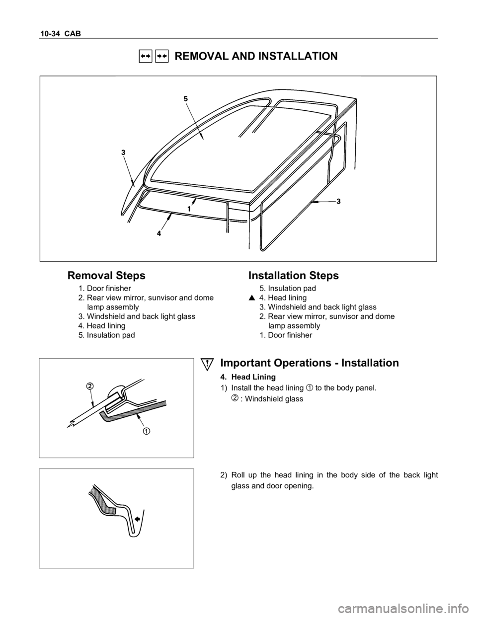
10-34 CAB
REMOVAL AND INSTALLATION
Removal Steps
1. Door finisher
2. Rear view mirror, sunvisor and dome
lamp assembly
3. Windshield and back light glass
4. Head lining
5. Insulation pad
Installation Steps
5. Insulation pad
4. Head lining
3. Windshield and back light glass
2. Rear view mirror, sunvisor and dome
lamp assembly
1. Door finisher
Important Operations - Installation
4. Head Lining
1) Install the head lining
1 to the body panel.
2 : Windshield glass
2) Roll up the head lining in the body side of the back light
glass and door opening.
Page 553 of 1600

CLUTCH 7C-13
SERVICING
Servicing refers to general maintenance procedures to be performed by qualified service personnel.
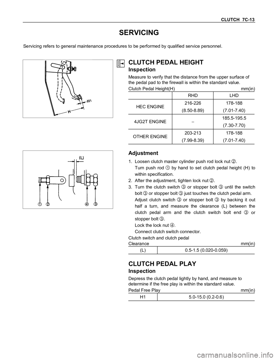
CLUTCH PEDAL HEIGHT
Inspection
Measure to verify that the distance from the upper surface of
the pedal pad to the firewall is within the standard value.
Clutch Pedal Height(H) mm(in)
RHD LHD
HEC ENGINE216-226
(8.50-8.89)178-188
(7.01-7.40)
4JG2T ENGINE185.5-195.5
(7.30-7.70)
OTHER ENGINE203-213
(7.99-8.39)178-188
(7.01-7.40)
Adjustment
1. Loosen clutch master cylinder push rod lock nut
2.
Turn push rod
1 by hand to set clutch pedal height (H) to
within specification.
2. After the adjustment, tighten lock nut
2.
3. Turn the clutch switch
3 or stopper bolt
3 until the switch
bolt
3 or stopper bolt
3 just touches the clutch pedal arm.
Adjust clutch switch
3 or stopper bolt
3 by backing it out
half a turn, and measure the clearance (L) between the
clutch pedal arm and the clutch switch bolt end
3 or
stopper bolt
3.
Lock the lock nut
4.
Connect clutch switch connector.
Clutch switch and clutch pedal
Clearance mm(in)
(L) 0.5-1.5 (0.020-0.059)
CLUTCH PEDAL PLAY
Inspection
Depress the clutch pedal lightly by hand, and measure to
determine if the free play is within the standard value.
Pedal Free Play mm(in)
H1 5.0-15.0 (0.2-0.6)