maintenance ISUZU TFS SERIES 1997 Workshop Manual
[x] Cancel search | Manufacturer: ISUZU, Model Year: 1997, Model line: TFS SERIES, Model: ISUZU TFS SERIES 1997Pages: 1600, PDF Size: 40.98 MB
Page 328 of 1600

NOTICE
Before using this Workshop Manual to assist you in performing vehicle
service and maintenance operations, it is recommended that you
carefully read and thoroughly understand the information contained in
Section - OA under the headings “GENERAL REPAIR
INSTRUCTIONS” and “HOW TO USE THIS MANUAL”.
All material contained in this Manual is based on the latest product
information available at the time of publication.
All rights are reserved to make changes at any time without prior
notice.
Page 345 of 1600

BRAKES 5-17
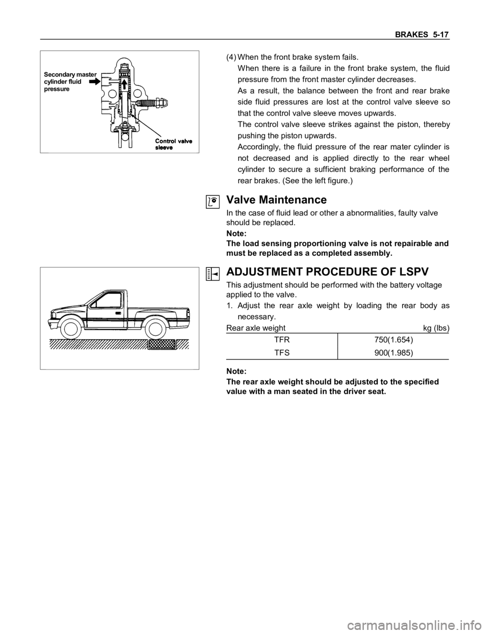
Secondary master
cylinder fluid
pressure
(4) When the front brake system fails.
W hen there is a failure in the front brake system, the fluid
pressure from the front master cylinder decreases.
As a result, the balance between the front and rear brake
side fluid pressures are lost at the control valve sleeve so
that the control valve sleeve moves upwards.
The control valve sleeve strikes against the piston, thereby
pushing the piston upwards.
Accordingly, the fluid pressure of the rear mater cylinder is
not decreased and is applied directly to the rear wheel
cylinder to secure a sufficient braking performance of the
rear brakes. (See the left figure.)
Valve Maintenance
In the case of fluid lead or other a abnormalities, faulty valve
should be replaced.
Note:
The load sensing proportioning valve is not repairable and
must be replaced as a completed assembly.
ADJUSTMENT PROCEDURE OF LSPV
This adjustment should be performed with the battery voltage
applied to the valve.
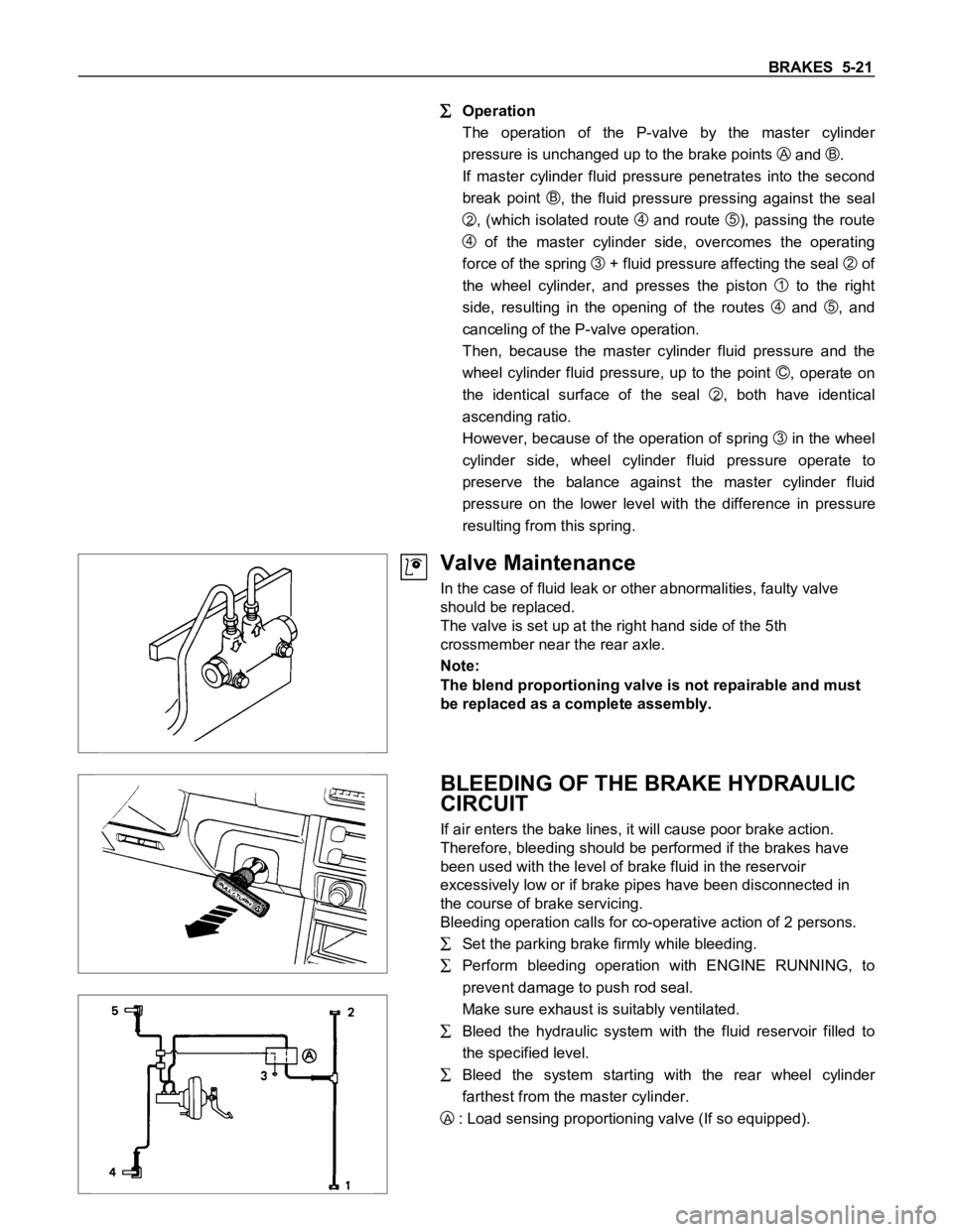
1. Adjust the rear axle weight by loading the rear body as
necessary.
Rear axle weight kg (lbs)
TFR 750(1.654)
TFS 900(1.985)
Note:
The rear axle weight should be adjusted to the specified
value with a man seated in the driver seat.
Page 349 of 1600

BRAKES 5-21
Operation
The operation of the P-valve by the master cylinder
pressure is unchanged up to the brake points
A and B.
If master cylinder fluid pressure penetrates into the second
break point
B, the fluid pressure pressing against the seal
2, (which isolated route 4 and route 5), passing the route
4 of the master cylinder side, overcomes the operating
force of the spring
3 + fluid pressure affecting the seal 2 of
the wheel cylinder, and presses the piston
1 to the right
side, resulting in the opening of the routes
4 and 5, and
canceling of the P-valve operation.
Then, because the master cylinder fluid pressure and the
wheel cylinder fluid pressure, up to the point
C, operate on
the identical surface of the seal
2, both have identical
ascending ratio.
However, because of the operation of spring
3 in the wheel
cylinder side, wheel cylinder fluid pressure operate to
preserve the balance against the master cylinder fluid
pressure on the lower level with the difference in pressure
resulting from this spring.
Valve Maintenance
In the case of fluid leak or other abnormalities, faulty valve
should be replaced.
The valve is set up at the right hand side of the 5th
crossmember near the rear axle.
Note:
The blend proportioning valve is not repairable and must
be replaced as a complete assembly.
BLEEDING OF THE BRAKE HYDRAULIC
CIRCUIT
If air enters the bake lines, it will cause poor brake action.
Therefore, bleeding should be performed if the brakes have
been used with the level of brake fluid in the reservoir
excessively low or if brake pipes have been disconnected in
the course of brake servicing.
Bleeding operation calls for co-operative action of 2 persons.
Set the parking brake firmly while bleeding.
Perform bleeding operation with ENGINE RUNNING, to
prevent damage to push rod seal.
Make sure exhaust is suitably ventilated.
Bleed the hydraulic system with the fluid reservoir filled to
the specified level.
Bleed the system starting with the rear wheel cylinder
farthest from the master cylinder.
A : Load sensing proportioning valve (If so equipped).
Page 454 of 1600

NOTICE
Before using this Workshop Manual to assist you in performing vehicle
service and maintenance operations, it is recommended that you
carefully read and thoroughly understand the information contained in
Section -
A under the headings "GENERAL REPAIR
INSTRUCTIONS" and "HOW TO USE THIS MANUAL".
All material contained in this Manual is based on the latest product
information available at the time of publication.
All rights are reserved to make changes at any time without prior
notice.
Page 540 of 1600

NOTICE
Before using this Workshop Manual to assist you in performing vehicle
service and maintenance operations, it is recommended that you
carefully read and thoroughly understand the information contained in
Section - OA under the headings “GENERAL REPAIR
INSTRUCTIONS” and “HOW TO USE THIS MANUAL”.
All material contained in this Manual is based on the latest product
information available at the time of publication.
All rights are reserved to make changes at any time without prior
notice.
Page 553 of 1600

CLUTCH 7C-13
SERVICING
Servicing refers to general maintenance procedures to be performed by qualified service personnel.
CLUTCH PEDAL HEIGHT
Inspection
Measure to verify that the distance from the upper surface of
the pedal pad to the firewall is within the standard value.
Clutch Pedal Height(H) mm(in)
RHD LHD
HEC ENGINE216-226
(8.50-8.89)178-188
(7.01-7.40)
4JG2T ENGINE185.5-195.5
(7.30-7.70)
OTHER ENGINE203-213
(7.99-8.39)178-188
(7.01-7.40)
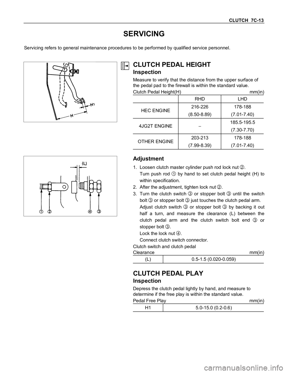
Adjustment
1. Loosen clutch master cylinder push rod lock nut
2.
Turn push rod
1 by hand to set clutch pedal height (H) to
within specification.
2. After the adjustment, tighten lock nut
2.
3. Turn the clutch switch
3 or stopper bolt
3 until the switch
bolt
3 or stopper bolt
3 just touches the clutch pedal arm.
Adjust clutch switch
3 or stopper bolt
3 by backing it out
half a turn, and measure the clearance (L) between the
clutch pedal arm and the clutch switch bolt end
3 or
stopper bolt
3.
Lock the lock nut
4.
Connect clutch switch connector.
Clutch switch and clutch pedal
Clearance mm(in)
(L) 0.5-1.5 (0.020-0.059)
CLUTCH PEDAL PLAY
Inspection
Depress the clutch pedal lightly by hand, and measure to
determine if the free play is within the standard value.
Pedal Free Play mm(in)
H1 5.0-15.0 (0.2-0.6)