wheel bolts ISUZU TFS SERIES 1997 Workshop Manual
[x] Cancel search | Manufacturer: ISUZU, Model Year: 1997, Model line: TFS SERIES, Model: ISUZU TFS SERIES 1997Pages: 1600, PDF Size: 40.98 MB
Page 64 of 1600

FRONT WHEEL DRIVE 4C1-1
SECTION 4C1
FRONT WHEEL DRIVE
TABLE OF CONTENTS
PAGE
Main Data and Specifications ...................................<0011001100110011001100110011001100110011001100110011001100110011001100110011001100110011001100110011001100110011001100110011001100110011001100110011001100110011001100110011001100110011001100110011001100
1100110011[ 4C1- 3
Special Parts Fixing Nuts and Bolts ............................................................................. 4C1- 4
Recommended Liquid Gasket ....................................................................................... 4C1- 7
Recommended Thread Locking Agents ....................................................................... 4C1- 7
Servicing<0011001100110011001100110011001100110011001100110011001100110011001100110011001100110011001100110011001100110011001100110011001100110011001100110011001100110011001100110011001100110011001100110011001100
11001100110011[<0011001100110011001100110011001100110011001100110011001100110011001100110011001100110011001100110011001100110011001100110011001100110011001100110011001100110011001100110011001100110011001100110011001100
11001100110011001100110011001100110011001100110011[..... 4C1- 8
General Description........................................................................................................ 4C1-9
Front Drive Axle Assembly............................................................................................ 4C1-12
Removal and Installation .......................................<0011001100110011001100110011001100110011001100110011001100110011001100110011001100110011001100110011001100110011001100110011001100110011001100110011001100110011001100110011001100110011001100110011001100
110011[ 4C1-12
Disassembly <0011001100110011001100110011001100110011001100110011001100110011001100110011001100110011001100110011001100110011001100110011001100110011001100110011001100110011001100110011001100110011001100110011001100
110011[<0011001100110011001100110011001100110011001100110011001100110011001100110011001100110011001100110011001100110011001100110011001100110011001100110011001100110011001100110011001100110011001100110011001100
1100110011001100110011001100110011[ 4C1-15
Inspection and Repair................................................................................................ 4C1-18
Reassembly <0011001100110011001100110011001100110011001100110011001100110011001100110011001100110011001100110011001100110011001100110011001100110011001100110011001100110011001100110011001100110011001100110011001100
1100110011[<0011001100110011001100110011001100110011001100110011001100110011001100110011001100110011001100110011001100110011001100110011001100110011001100110011001100110011001100110011001100110011001100110011001100
1100110011001100110011001100110011[ 4C1-19
Differential ....................................................................................................................... 4C1-22
Disassembly <0011001100110011001100110011001100110011001100110011001100110011001100110011001100110011001100110011001100110011001100110011001100110011001100110011001100110011001100110011001100110011001100110011001100
110011[<0011001100110011001100110011001100110011001100110011001100110011001100110011001100110011001100110011001100110011001100110011001100110011001100110011001100110011001100110011001100110011001100110011001100
1100110011001100110011001100110011[ 4C1-22
Major Components ............................................................................................... 4C1-22
Minor Components............................................................................................... 4C1-25
Inspection and Repair................................................................................................ 4C1-27
Reassembly <0011001100110011001100110011001100110011001100110011001100110011001100110011001100110011001100110011001100110011001100110011001100110011001100110011001100110011001100110011001100110011001100110011001100
1100110011[<0011001100110011001100110011001100110011001100110011001100110011001100110011001100110011001100110011001100110011001100110011001100110011001100110011001100110011001100110011001100110011001100110011001100
1100110011001100110011001100110011[ 4C1-29
Minor Components............................................................................................... 4C1-29
Major Components ............................................................................................... 4C1-31
Front Hub and Disc (4
2 Model) .................................................................................... 4C1-41
Disassembly <0011001100110011001100110011001100110011001100110011001100110011001100110011001100110011001100110011001100110011001100110011001100110011001100110011001100110011001100110011001100110011001100110011001100
110011[<0011001100110011001100110011001100110011001100110011001100110011001100110011001100110011001100110011001100110011001100110011001100110011001100110011001100110011001100110011001100110011001100110011001100
1100110011001100110011001100110011[ 4C1-41
Inspection and Repair................................................................................................ 4C1-44
Reassembly <0011001100110011001100110011001100110011001100110011001100110011001100110011001100110011001100110011001100110011001100110011001100110011001100110011001100110011001100110011001100110011001100110011001100
1100110011[<0011001100110011001100110011001100110011001100110011001100110011001100110011001100110011001100110011001100110011001100110011001100110011001100110011001100110011001100110011001100110011001100110011001100
1100110011001100110011001100110011[ 4C1-45
Front Hub and Disc (4
4 Model) .................................................................................... 4C1-48
Disassembly <0011001100110011001100110011001100110011001100110011001100110011001100110011001100110011001100110011001100110011001100110011001100110011001100110011001100110011001100110011001100110011001100110011001100
110011[<0011001100110011001100110011001100110011001100110011001100110011001100110011001100110011001100110011001100110011001100110011001100110011001100110011001100110011001100110011001100110011001100110011001100
1100110011001100110011001100110011[ 4C1-48
Inspection and Repair................................................................................................ 4C1-50
Reassembly <0011001100110011001100110011001100110011001100110011001100110011001100110011001100110011001100110011001100110011001100110011001100110011001100110011001100110011001100110011001100110011001100110011001100
1100110011[<0011001100110011001100110011001100110011001100110011001100110011001100110011001100110011001100110011001100110011001100110011001100110011001100110011001100110011001100110011001100110011001100110011001100
1100110011001100110011001100110011[ 4C1-51
Front Hub and Disc (Automatic Locking Hub) ............................................................. 4C1-54
INDEX
Page 67 of 1600

4C1-4 FRONT WHEEL DRIVE
SPECIAL PARTS FIXING NUTS AND BOLTS
FRONT DRIVE AXLE AND PROPELLER SHAFT
Nm (kgfm/lbft)
152.114.7 (15.51.5/112.10.8)82.4
7.8 (8.40.8/60.85.8) 167mm 35.3
2.9 (3.60.3/26.02.2)
194mm 62.8
3.9 (6.40.4/46.32.9)194mm 62.8
3.9
(6.4
0. 2/46.32.9) 167mm 35.3
2.9
(3.6
0.3/26.00.2)
Page 70 of 1600

FRONT WHEEL DRIVE 4C1-7
RECOMMENDED LIQUID GASKET
Type Brand Name Manufacture Remarks
RTV*
Silicon BaseThreeBond 1207B
ThreeBond 1207C
ThreeBond 1215Three Bond
Three Bond
Three BondFor Engine Repairs
For Axle Case
Repairs, T/M
Water Base ThreeBond 1141E Three Bond For Engine Repairs
SolventThreeBond 1104
BelcoBond 4
BelcoBond 401
BelcoBond 402Three bond
Isuzu
Isuzu
IsuzuFor Engine Repairs
AnerobicLOCTITE 515
LOCTITE 518Loctite
LoctiteAll
* RTV : Room Temperature Vulcanizer
Note :
1. It is very important that the liquid gaskets listed above or their exact equivalent be used on the vehicle.
2. Be careful to use the specified amount of liquid gasket.
Follow the manufacture's instructions at all times.
3. Be absolutely sure to remove all lubricants and moisture from the connecting surfaces before applying
the liquid gasket.
The connecting surfaces must be perfectly dry.
4. LOCTITE 515 and LOCTITE 518 harden upon contact with a metal surface.
Do not apply LOCTITE 515 or LOCTITE 518 between two metal surfaces having a clearance of greater
than 0.25 mm (0.01 in). Poor adhesion will result.
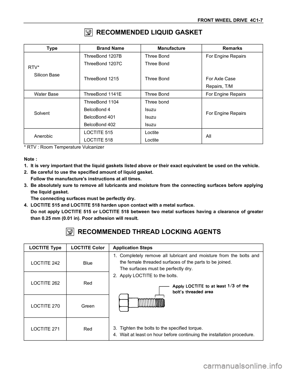
RECOMMENDED THREAD LOCKING AGENTS
LOCTITE Type LOCTITE Color Application Steps
LOCTITE 242 Blue1. Completely remove all lubricant and moisture from the bolts and
the female threaded surfaces of the parts to be joined.
The surfaces must be perfectly dry.
LOCTITE 262 Red2. Apply LOCTITE to the bolts.
LOCTITE 270 Green
LOCTITE 271 Red3. Tighten the bolts to the specified torque.
4. Wait at least on hour before continuing the installation procedure.
Page 76 of 1600

FRONT WHEEL DRIVE 4C1-13
Important Operations - Removal
1. Assembly of hub and disc, back plate, knuckle, knuckle
arm, and lower end.
Before removal, jack up the front of vehicle and support the
frame with jack stands.
2. Propeller Shaft
Apply the setting marks.
5. Front Drive Axle Assembly
(1) Put the lifting jack under the center part of the front.
(2) Remove four bolts fixing axle case mounting brackets to the
frame.
Note :
Be careful not to damage birfield joints or double off-set
joints when supporting axle shaft assembly.
(3) Lower the front axle assembly and roll it out toward the front
of the vehicle.
Take care not to damage the birfield joints or the double off-
set joints.
Page 90 of 1600

FRONT WHEEL DRIVE 4C1-27
INSPECTION AND REPAIR
Make all necessary adjustments, repairs, and part replacements if wear, damage, or other problems are discovered
during inspection.
Ring gear, pinion gear
Bearing
Side gear, pinion gear, cross pin
Differential cage, carrier
Thrust washer
Oil seal
Visual Check
Inspect the following parts for wear, damage, or other
abnormal conditions.
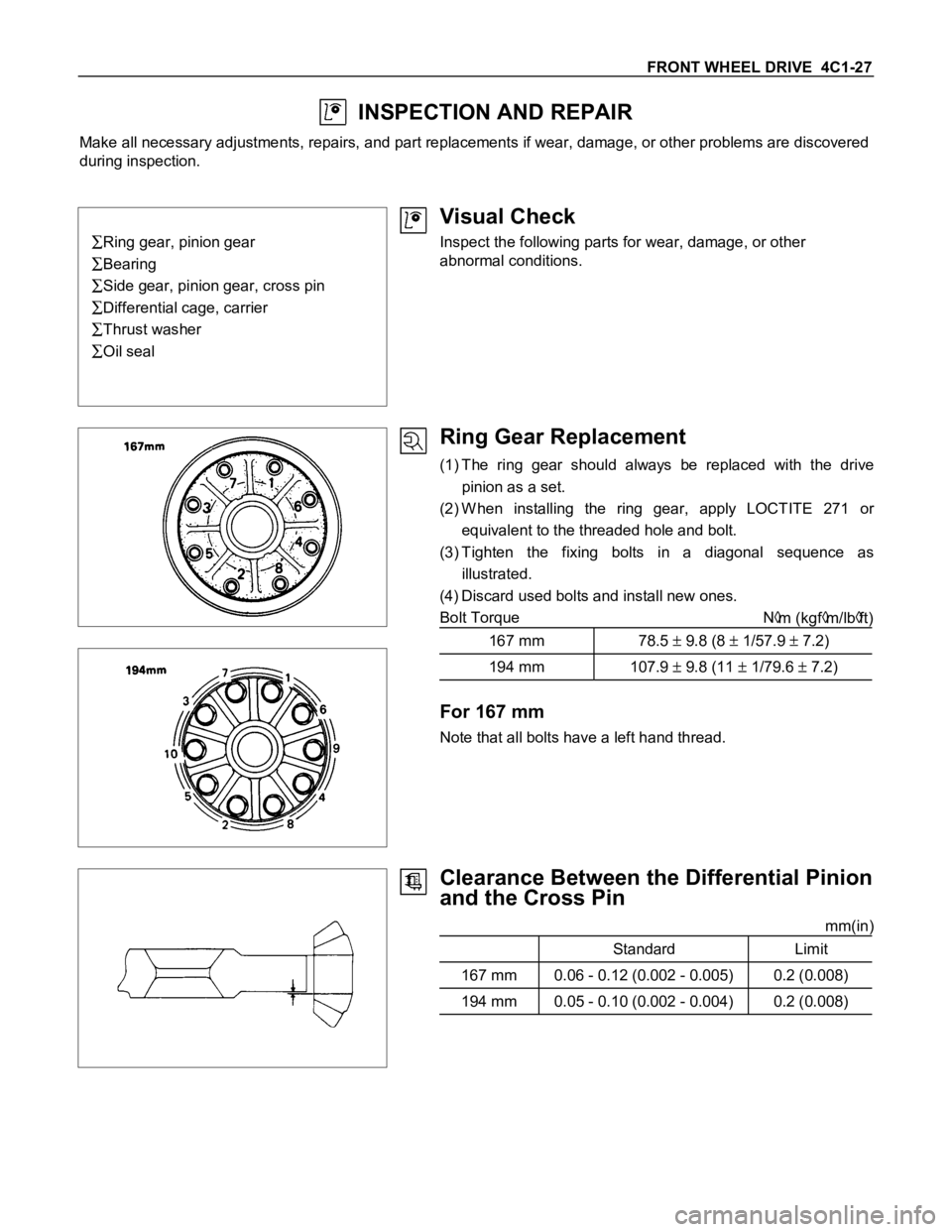
Ring Gear Replacement
(1) The ring gear should always be replaced with the drive
pinion as a set.
(2) W hen installing the ring gear, apply LOCTITE 271 or
equivalent to the threaded hole and bolt.
(3) Tighten the fixing bolts in a diagonal sequence as
illustrated.
(4) Discard used bolts and install new ones.
Bolt Torque N
m (kgfm/lbft)
167 mm 78.5
9.8 (8 1/57.9 7.2)
194 mm 107.9 9.8 (11 1/79.6 7.2)
For 167 mm
Note that all bolts have a left hand thread.
Clearance Between the Differential Pinion
and the Cross Pin
mm(in)
Standard Limit
167 mm 0.06 - 0.12 (0.002 - 0.005) 0.2 (0.008)
194 mm 0.05 - 0.10 (0.002 - 0.004) 0.2 (0.008)
Page 93 of 1600

4C1-30 FRONT WHEEL DRIVE
5. Cross Pin
(1) Be sure to install the cross pin so that it is in alignment with
the lock pin hole in the differential cage.
(2) Adjust the backlash between the side gear and the pinion
gear.
mm(in)
Backlash 0.03 - 0.08 (0.001 - 0.003)
Thickness of thrust washers available
mm(in)
167 mm 1.05, 1.15, 1.25 (0.041, 0.043, 0.049)
194 mm 1.00, 1.05, 1.10 (0.039, 0.041, 0.043)
6. Lock Pin
After lock pin installation, stake the cage to prevent discharge
of the lock pin.
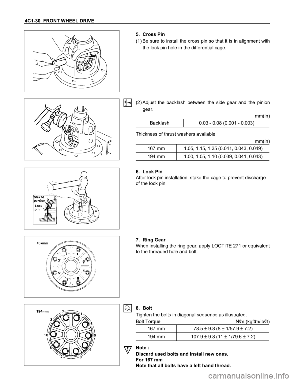
7. Ring Gear
When installing the ring gear, apply LOCTITE 271 or equivalent
to the threaded hole and bolt.
8. Bolt
Tighten the bolts in diagonal sequence as illustrated.
Bolt Torque N
m (kgfm/lbft)
167 mm 78.5
9.8 (8 1/57.9 7.2)
194 mm 107.9 9.8 (11 1/79.6 7.2)
Note :
Discard used bolts and install new ones.
For 167 mm
Note that all bolts have a left hand thread.
Page 103 of 1600

4C1-40 FRONT WHEEL DRIVE
20.Differential Assembly
(1) Clean the faces of the front axle case and differential
carrier.
Apply the recommended liquid gasket or its equivalent to
the sealing side of the axle case and the carrier.
(2) Attach the differential case and the carrier assembly to the
front axle case and tighten the nuts and bolts. The axle
case bolt is used for drainage.
Torque N
m (kgfm/lbft)
25.5
5 (2.6 0.5/18.8 3.6)
(3) Install the axle shaft assemblies as instructed earlier in this
section under “Axle Shaft Replacement”.
(4) Fill the axle case with hypoid gear lubricant, to just below
the filler hole.
Lubricant capacity liter (US/UK gal)
167 mm 1.0 (0.26/0.22)
194 mm 1.4 (0.37/0.31)
Page 105 of 1600

4C1-42 FRONT WHEEL DRIVE
Important Operations
Before removal, jack up the front of vehicle and support frame
with jack stands.
2. Brake Caliper
(1) Remove the two bolts from the rear side of the knuckle arm,
then remove the brake caliper, with the brake hose
attached.
(2) Use a wire etc., for attaching the brake caliper to the upper
link.
3. Hub Cap
When removing hub cap, exercise care so as not to scratch or
distort hub fitting face.
9. Hub and Disc Assembly
Using a brass bar to remove the outer bearing outer race (1),
oil seal, inner bearing and inner bearing outer race (2) from the
hug.
If necessary, replace the wheel pin in the following manner.
12.Bolt
13.Wheel Pin ; Front Hub
(1) Scribe mark on hub to disc before disassembly to insure
proper assembly.
Page 106 of 1600

FRONT WHEEL DRIVE 4C1-43
(2) Clamp hub and disc assembly in vise using protective pads
and remove six (6) disc to hub retaining bolts.
(3) Place hub on a suitable work surface and remove wheel
studs, as required, using a hammer.
Page 118 of 1600

FRONT WHEEL DRIVE 4C1-55
Important Operations
1. Bolt
Shift the transfer lever to the “2H” position and move the
vehicle forward and rearward about one meter.
Remove the 14 mm hex bolts.
8. Hub Nut
Wrench : 5-8840-2117-0
(J-36827)
Refer to Section 5 “Brake” for disc brake
caliper removal procedure9. Hub and Disc Assembly
Before disassembly, remove the disc brake caliper assembly
and hang it on the frame with wires.
10.Outer Bearing and Outer Race
12.Inner Bearing and Outer Race
(1) Remove the outer bearing from the hub with fingers. The
inner bearing will remain in the hub and may be removed
after prying out the inner bearing lip seal assembly.
(2) Remove the outer race by driving out the race from the hub
with a brass drift inserted behind the race in the notches in
the hubs.
If necessary, replace the wheel pin in the following manner.
13.Bolt
(1) Apply a scribe mark to disc to hub.
(2) Clamp the hub and disc assembly in a vise using protective
pads and remove the 6 disc to hub retaining bolts.