oil filter ISUZU TROOPER 1995 User Guide
[x] Cancel search | Manufacturer: ISUZU, Model Year: 1995, Model line: TROOPER, Model: ISUZU TROOPER 1995Pages: 1928
Page 612 of 1928
6A1-54 ENGINE (V6 3.2L DOHC AND SOHC)
1••1 REMOVAL
1. Timing belt
• See "Timing Belt Removal and Installation".
2. Crankshaft timing pulley
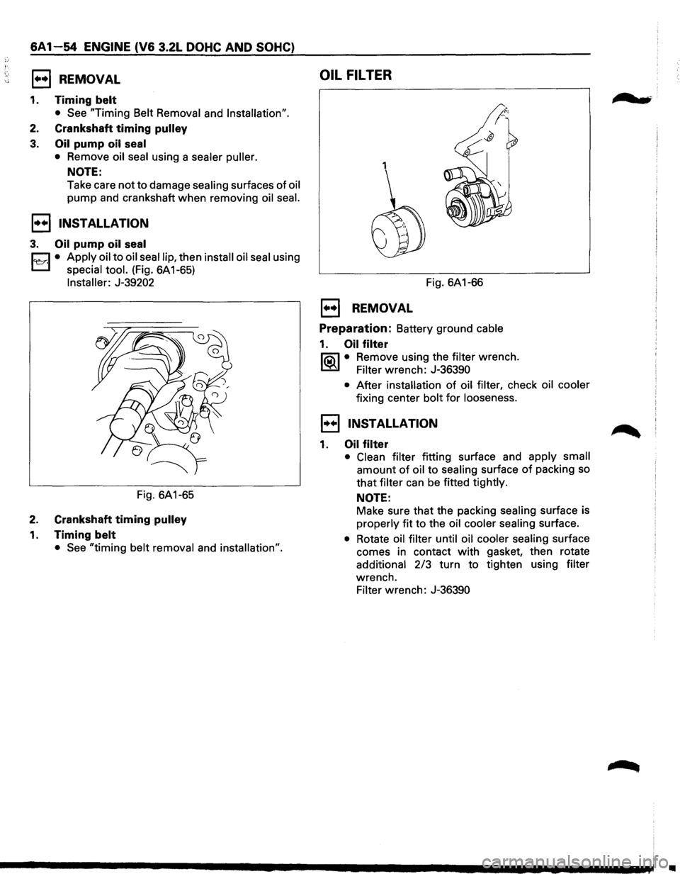
3. Oil pump oil seal
• Remove oil seal using a sealer puller.
NOTE:
Take care not to damage sealing surfaces of oil
pump and crankshaft when removing oil seal.
1••1 INSTALLATION
3. Oil pump oil seal
Cl • Apply oil to oil seal lip, then install oil seal using
L..:::::.l special tool. (Fig. 6A1-65)
Installer: J-39202
Fig. 6A1-65
2. Crankshaft timing pulley
1. Timing belt
• See "timing belt removal and installation".
OIL FILTER
1
Fig. 6A1-66
E) REMOVAL
Preparation: Battery ground cable
1. Oil filter
lia\l • Remove using the filter wrench.
~ Filter wrench: J-36390
• After installation of oil filter, check oil cooler
fixing center bolt for looseness.
1••1 INSTALLATION
1. Oil filter
• Clean filter fitting surface and apply small
amount of oil to sealing surface of packing so
that filter can be fitted tightly.
NOTE:
Make sure that the packing sealing surface is
properly fit to the oil cooler sealing surface.
• Rotate oil filter until oil cooler sealing surface
comes in contact
with gasket, then rotate
additional 2/3 turn to tighten using filter
wrench.
Filter wrench: J-36390
, ...
Page 613 of 1928
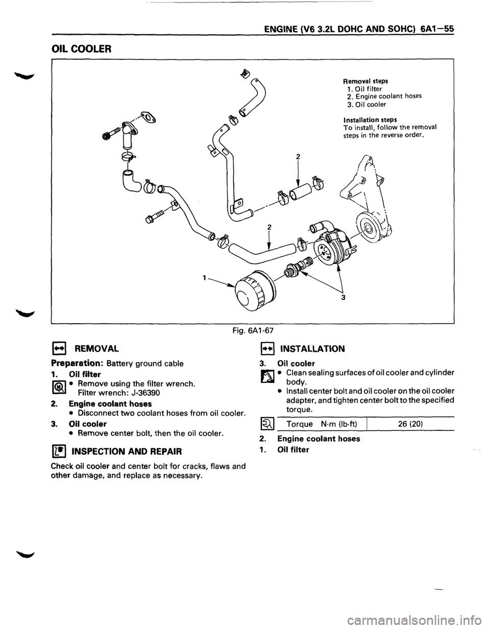
OIL COOLER
1
ENGINE (V6 3.2L DOHC AND SOHC) 6A 1-55
Removal steps
1.
Oil filter 2. Engine coolant hoses
3. Oil cooler
Installation
steps To install, follow the removal steps in the reverse order.
3
Fig. 6A1-67
1••1 REMOVAL
Preparation: Battery ground cable
1. Oil filter
li5\1 • Remove using the filter wrench.
~ Filter wrench: J-36390
2. Engine
coolant hoses
• Disconnect two coolant hoses from oil cooler.
3. Oil cooler
• Remove center bolt, then the oil cooler.
U!)INSPECTION AND REPAIR
Check oil cooler and center bolt for cracks, flaws and
other damage, and
replace as necessary.
1••1 INSTALLATION
3. Oil cooler
m • Clean sealing surfaces of oil cooler and cylinder
L41 body.
• Install center bolt and oil cooler on the oil cooler
adapter, and tighten center bolt to the specified
torque.
~~~ Torque N·m (lb·ft) 26 (20)
2. Engine coolant hoses
1.
Oil filter
Page 627 of 1928
ENGINE (V6 3.2L DOHC AND SOHC) 6A1-69
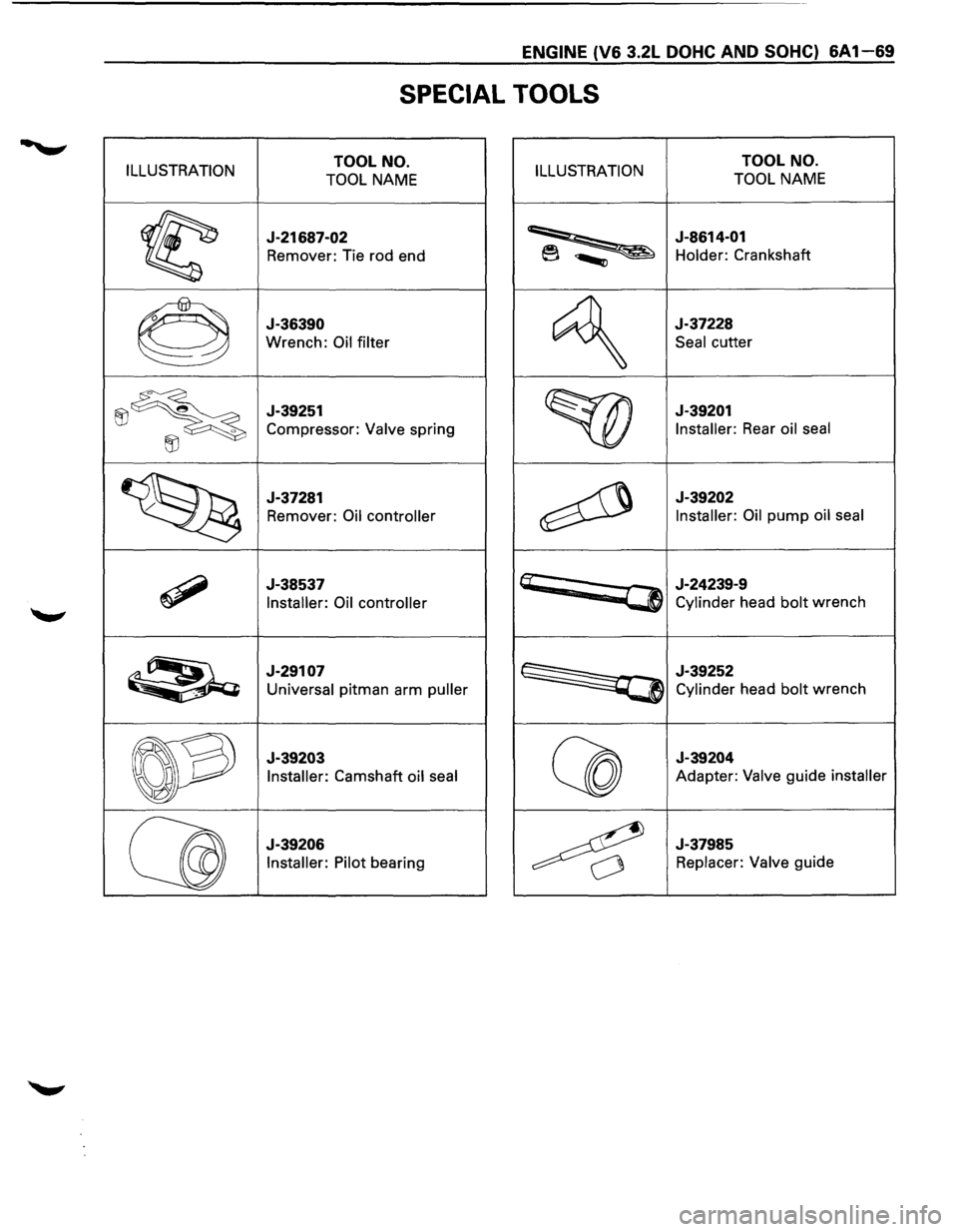
SPECIAL TOOLS
ILLUSTRATION TOOL NO.
TOOL NAME ILLUSTRATION TOOL NO.
TOOL NAME
~
J-21687-02
Remover: Tie rod end ~
J-8614-01
Holder: Crankshaft
0
J-36390
Wrench: Oil filter
~
J-37228
Seal cutter
~~
J-39251
Compressor: Valve spring
~ ~
J-39201
Installer:
Rear oil seal
~
J-37281
Remover:
Oil controller ~
J-39202
Installer: Oil
pump oil seal
~
J-38537
Installer: Oil controller
~
~
J-24239-9
Cylinder head bolt wrench
~
J-29107
Universal pitman arm puller ~
J-39252
Cylinder head bolt wrench
~
J-39203
Installer:
Camshaft oil seal Q co
J-39204
Adapter: Valve guide installer
Qg
J-39206 Installer: Pilot
bearing 4
J-37985
Replacer: Valve guide
Page 643 of 1928
ENGINE FUEL 6C-1
SECTION 6C
ENGINE FUEL
CONTENTS
General Description ....................... .
Fuel Metering ............................ .
On-Vehicle Service ........................ .
Fuel Filter ................................. .
In Tank Fuel Filter ............................. .
Fuel Pump Flow Test ........................ .
Fuel Pump Assembly ........................ .
Fuel Pump Relay .............................. ..
6C-1
6C-2
6C-3
6C-3
6C-4
6C-4
6C-5
6C-5
Fuel Tank .......................................... ..
Fuel Gage Unit ................................. ..
Fuel Filler Cap .................................... .
Accelerator Pedal Control ............... ..
Accelerator Pedal Control Cable ..
Accelerator Pedal ......................... .
Air
Cleaner Filter ........................... .
Main Data and Specifications ............... .
Torque Specifications ......................
..
6C-6
6C-7
6C-7
6C-8
6C-8
6C-9
6C-10
6C-11
6C-11
GENERAL DESCRIPTION
When working on the fuel system, there are several
things to keep in mind:
• Any time the fuel system is being worked on,
disconnect the negative battery
cable except for
those tests where battery voltage is required.
• Always keep a dry chemical (Class 8) fire extin
guisher near the work area.
• Replace all pipes with the same pipe and fittings
that were removed.
• Clean and inspect "0" rings. Replace if required.
• Always relieve the line pressure before servicing
any fuel system components.
• Do not attempt repairs on the fuel system until you
have read the instructions and checked the pic
tures
relating to that repair.
• Adhere to all Notices and Cautions.
All gasoline engines are designed to use only unleaded
gasoline. Unleaded gasoline
must be used for proper
emission control system operation. Its use will also
minimize spark plug fouling and extend engine oil life.
Using leaded gasoline can damage the emission
control system and could result in loss of emission
warranty coverage.
All cars are equipped with an Evaporative Emission
Control System. The purpose of the system is to
minimize the escape offuel vapors to the atmosphere.
Information on this system will be found in Section
6E2.
Page 787 of 1928
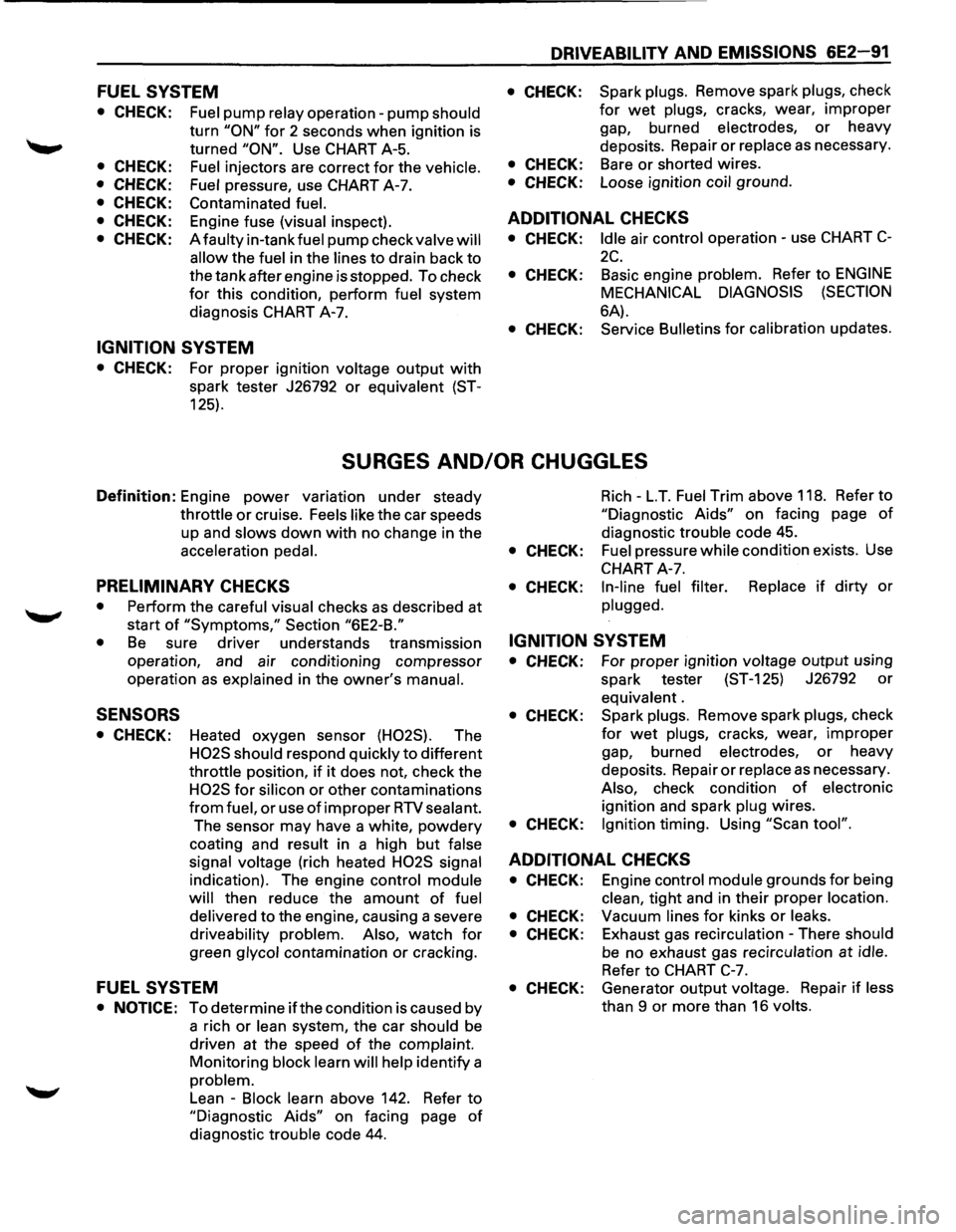
FUEL SYSTEM
• CHECK:
• CHECK:
• CHECK:
• CHECK:
• CHECK:
• CHECK:
Fuel pump relay operation-pump should
turn "ON" for 2 seconds when ignition is
turned
"ON". Use CHART A-5.
Fuel injectors are correct for the vehicle.
Fuel
pressure, use CHART A-7.
Contaminated
fuel.
Engine fuse (visual inspect).
A
faulty in-tank fuel pump check valve will
allow
the fuel in the lines to drain back to
the tank after engine is stopped. To check
for this condition, perform fuel system
diagnosis CHART A-7.
IGNITION SYSTEM
• CHECK: For proper ignition voltage output with
spark tester J26792 or equivalent (ST-
125).
DRIVEABILITY AND EMISSIONS 6E2-91
• CHECK: Spark plugs. Remove spark plugs, check
for wet plugs, cracks, wear, improper
gap, burned electrodes, or heavy
deposits. Repair
or replace as necessary.
• CHECK: Bare or shorted wires.
• CHECK: Loose ignition coil ground.
ADDITIONAL CHECKS
• CHECK: Idle air control operation-use CHART C-
2C.
• CHECK: Basic engine problem. Refer to ENGINE
MECHANICAL DIAGNOSIS (SECTION
6A).
• CHECK: Service Bulletins for calibration updates.
SURGES AND/OR CHUGGLES
Definition: Engine power variation under steady
throttle or cruise. Feels like the car speeds
up and
slows down with no change in the
acceleration pedal.
PRELIMINARY CHECKS
• Perform the careful visual checks as described at
start
of "Symptoms," Section "6E2-B."
•
Be sure driver understands transmission
operation, and air conditioning compressor
operation
as explained in the owner's manual.
SENSORS
• CHECK: Heated oxygen sensor (H02S). The
H02S should respond quickly to different
throttle position, if it does not, check the
H02S for silicon or other contaminations
from fuel, or use of improper RTV sealant.
The sensor may have a white, powdery
coating and result in a high but false
signal voltage
(rich heated H02S signal
indication). The engine control module
will
then reduce the amount of fuel
delivered
to the engine, causing a severe
driveability problem. Also, watch for
green glycol contamination or cracking.
FUEL SYSTEM
• NOTICE: To determine ifthe condition is caused by
a rich
or lean system, the car should be
driven at the speed of the complaint.
Monitoring block learn will help identify a
problem.
Lean -Block learn above 142. Refer to
"Diagnostic Aids" on facing page of
diagnostic trouble code 44.
Rich -L.T. Fuel Trim above 118. Refer to
"Diagnostic Aids" on facing page of
diagnostic trouble code 45.
• CHECK: Fuel pressure while condition exists. Use
CHART A-7.
• CHECK: In-line fuel filter. Replace if dirty or
plugged.
IGNITION SYSTEM
• CHECK: For proper ignition voltage output using
spark tester (ST-125) J26792
or
equivalent .
• CHECK: Spark plugs. Remove spark plugs, check
for wet plugs, cracks, wear, improper
gap, burned electrodes, or heavy
deposits. Repair
or replace as necessary.
Also, check condition of electronic
ignition and spark plug wires.
• CHECK: Ignition timing. Using "Scan tool".
ADDITIONAL CHECKS
• CHECK: Engine control module grounds for being
clean, tight and in their proper location.
• CHECK: Vacuum lines for kinks or leaks.
• CHECK: Exhaust gas recirculation -There should
be no exhaust gas recirculation at idle.
Refer to CHART C-7.
• CHECK: Generator output voltage. Repair if less
than 9 or more than 16 volts.
Page 788 of 1928
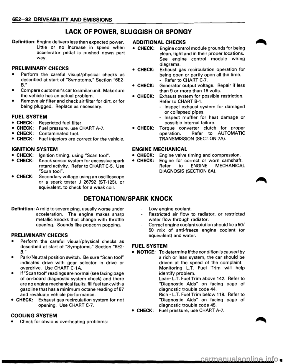
6E2-92 DRIVEABILITY AND EMISSIONS
LACK OF POWER, SLUGGISH OR SPONGY
Definition: Engine delivers less than expected power.
Little or no increase in speed when
accelerator
pedal is pushed down part
way.
PRELIMINARY CHECKS
• Perform the careful visual/physical checks as
described at start of "Symptoms," Section "6E2-
B."
•
Compare customer's car to similar unit. Make sure
the
vehicle has an actual problem.
• Remove air filter and check air filter for dirt, or for
being plugged. Replace as necessary.
FUEL SYSTEM
• CHECK: Rescricted fuel filter.
• CHECK: Fuel pressure, use CHART A-7.
• CHECK: Contaminated fuel.
• CHECK: Fuel injectors are correct for the vehicle.
IGNITION SYSTEM
• CHECK: Ignition timing, using "Scan tool".
• CHECK: Knock sensor system for excessive spark
retard activity. Refer to CHART
C-5. Use
"Scan tool".
• CHECK: Secondary voltage using an oscilloscope
or a spark tester J 26792 (ST-125), or
equivalent, to check for a weak coil.
ADDITIONAL CHECKS
• CHECK: Engine control module grounds for being
clean,
tight and in their proper locations.
See engine control module wiring
diagrams.
• CHECK: Exhaust gas recirculation operation for
being open or partly open all the time.
- Refer to CHART
C-7.
• CHECK: Generator output voltage. Repair if less
than 9
or more than 16 volts.
• CHECK: Exhaust system for possible restriction.
Refer
to CHART B-1.
-Inspect exhaust system for damaged
or collapsed pipes.
-
Inspect muffler for heat damage or
possible internal failure.
• CHECK: Torque converter clutch for proper
operation. Refer
to AUTOMATIC
TRANSMISSION
(SECTION 7A).
ENGINE MECHANICAL
• CHECK: Engine valve timing and compression.
• CHECK: Engine for correct or worn camshaft.
Refer
to ENGINE MECHANICAL
DIAGNOSIS
(SECTION 6A).
DETONATION/SPARK KNOCK
Definition: A mild to severe ping, usually worse under
acceleration. The engine makes sharp
metallic knocks that change with throttle
opening.
Sounds like popcorn popping.
PRELIMINARY CHECKS
• Perform the careful visual/physical checks as
Low engine coolant.
Restricted air
flow to radiator, or restricted
water flow through radiator.
Correct engine
coolant solution should be a 50/
50 mix of anti-freeze engine coolant (or
equivalent) and water.
described at start
of "Symptoms," Section "6E2-FUEL SYSTEM
B."
•
Park/Neutral position switch. Be sure "Scan tool"
indicates drive with gear selector in drive or
overdrive. Use
CHART C-1A.
• If "Scan tool" readings are normal (see facing page
of on-board diagnostic system check) and there
are no engine mechanical faults,
fill fuel tank with a
gasoline
that has a minimum octane reading of 87
and revaluate vehicle performance.
• CHECK: Exhaust gas recirculation system for not
opening. Use CHART C-7.
COOLING SYSTEM
• Check for obvious overheating problems:
• NOTICE: To determine if the condition is caused by
a rich
or lean system, the car should be
driven at the speed
of the complaint.
Monitoring
LT. Fuel Trim will help
identify problem.
Lean-
LT. Fuel Trim above 142. Refer to
"Diagnostic Aids" on facing page of
diagnostic trouble code 44.
Rich-LT. Fuel Trim below 118. Refer to
"Diagnostic Aids" on facing page of
diagnostic trouble code 45.
• CHECK: Fuel pressure, use CHART A-7.
..
Page 906 of 1928
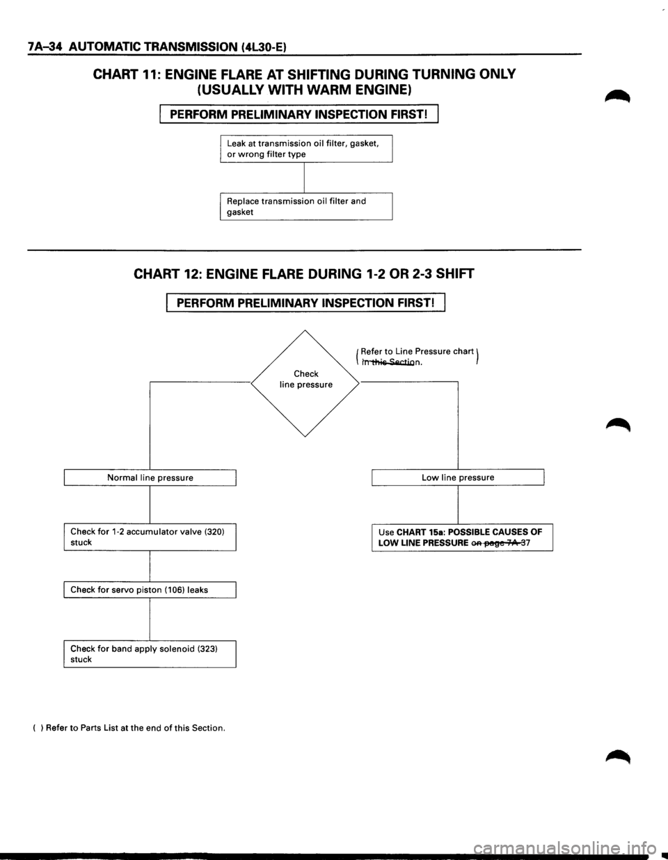
7 A-34 AUTOMATIC TRANSMISSION (4L30-E)
CHART 11: ENGINE FLARE AT SHIFTING DURING TURNING ONLY
(USUALLY WITH
WARM ENGINE)
PERFORM PRELIMINARY INSPECTION FIRST!
Leak at transmission oil filter, gasket, or wrong filter type
Replace transmission oil filter and
gasket
CHART 12: ENGINE FLARE DURING 1-2 OR 2-3 SHIFT
PERFORM PRELIMINARY INSPECTION FIRST!
Normal line pressure
Check for 1-2 accumulator valve (320) stuck
Check for servo piston (106) leaks
Check
for band apply solenoid (323) stuck
( ) Refer
to Parts List at the end of this Section.
Check
line pressure (
Refer
to Line
Pressure chart) t~n.
Low line pressure
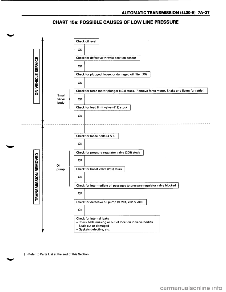
Use CHART 15a:
POSSIBLE CAUSES OF
LOW LINE PRESSURE ~fM!~e 71/1t 37
..
Page 908 of 1928
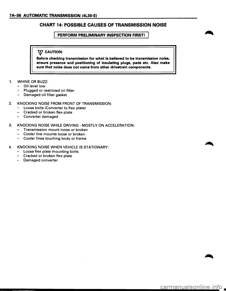
7 A-36 AUTOMATIC TRANSMISSION (4L30-E)
CHART 14: POSSIBLE CAUSES OF TRANSMISSION NOISE
PERFORM PRELIMINARY INSPECTION FIRST!
'\f CAUTION:
Before checking transmission for what is believed to be transmission noise,
ensure presence and
positioning of insulating plugs, pads etc. Also make
sure
that noise does not come from other drivetrain components.
1. WHINE OR BUZZ:
-
Oil level low
-Plugged or restricted oil filter
- Damaged oil filter gasket
2. KNOCKING NOISE FROM FRONT OF TRANSMISSION:
-Loose bolts (Converter to flex plate)
- Cracked or broken flex plate
-Converterdamaged
3. KNOCKING NOISE WHILE DRIVING- MOSTLY ON ACCELERATION:
-Transmission mount loose or broken
-
Cooler line mounts loose or broken
-
Cooler lines touching body or frame
4. KNOCKING NOISE WHEN VEHICLE IS STATIONARY:
-Loose flex plate mounting bolts
-Cracked or broken flex plate
-Damaged converter
II
Page 909 of 1928
w CJ s: a: w Cl)
w ..... CJ :E w > I z 0
AUTOMATIC TRANSMISSION (4L30..E) 7 A-37
CHART 15a: POSSIBLE CAUSES OF LOW LINE PRESSURE
Small
valve
body
Oil pump
{
Check oil level I
OK
Check for defective throttle position sensor I
OK
Check for plugged, loose, or damaged oil filter (79) I
OK
Check for force motor plunger (404) stuck. (Remove force motor. Shake and listen for rattle.) I
OK
Check for feed limit valve (412) stuck I
OK
------------------------------------------------------------------------
Check for loose bolts (4 & 5) I
OK
Check for pressure regulator valve (208) stuck I
OK
Check for boost valve (205) stuck I
OK
Check for intermediate oil passages to pressure regulator valve blocked I
OK
Check for defective oil pump (9, 201, 202 & 209) I
OK
Check for internal leaks -Check balls missing or out of location in valve bodies -Seals cut or damaged
-Gaskets defective, etc.
( ) Refer to Parts List at the end
of this Section.
Page 1037 of 1928
2. Exhaust and transfer protectors
~~~ Torque N-m(lb.ft) 37 (27)
1. Skid plate
• Connect negative (-) battery cable.
• Install
engine hood.
• Adjust shift lock cable.
Refer to "Selector lever" in this section.
SOLENOID VALVE
(MAIN CASE VALVE BODY)
l••l REMOVAL
Preparation:
• Disconnect negative {-) battery cable.
•
Remove exhaust protector and exhaust pipe.
1. Main case oil pan
• Remove sixteen 10 mm screws, main case
oil pan, magnet, and gasket.
• Drain fluid.
Refer to "CHANGING TRANSMISSION
FLUID".
2. Oil filter
• Remove three 13 mm screws, oil filter.
3. Wiring harness
• Disconnect wiring harness from band control
solenoid,
shift solenoids and main case 4 pin
connector.
Pull only on connectors, not on
wiring harness.
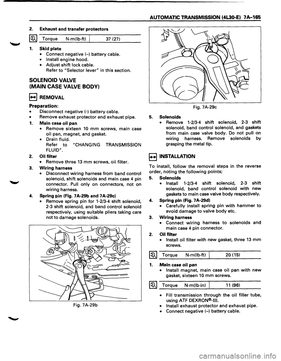
4. Spring pin (Fig. 7 A-29b and 7 A-29c)
• Remove spring pin for 1-2/3-4 shift solenoid,
2-3 shift solenoid, and band control solenoid
respectively,
using suitable pliers taking care
not to damage solenoids.
Fig. 7A-29b
AUTOMATIC TRANSMISSION (4L30 .. E) 7A-165
Fig. 7A-29c
5. Solenoids
• Remove 1-2/3-4 shift solenoid, 2-3 shift
solenoid, band control solenoid, and gaskets
from main case valve body. Do not pull on
wiring harness. Remove
· solenoids by
grasping the
metal tip.
I••! INSTALLATION
To install, follow the removal steps in the reverse
order,
noting the following points;
5. Solenoids
• Install 1-2/3-4 shift solenoid, 2-3 shift
solenoid, band control solenoid with new
gaskets to main case valve body respectively.
4. Spring pin (Fig. 7 A·29d)
• Carefully install spring pin with hammer to
avoid damage to valve body etc.
3. Wiring harness
• Connect wiring harness to solenoids and
main case 4 pin connector.
2. Oil filter
• Install oil filter with new gasket, three 13 mm
screws.
~~~ Torque N·m(lb.ft) 20 (15)
1. Main case oil pan
•
Install magnet, main case oil pan with new
gasket, sixteen 10 mm screws.
1~1 Torque N·m(lb·in) J 11 (96)
• Fill transmission through the oil filler tube,
using ATF DEXRQN®-m.
• Install exhaust protector and exhaust pipe.
• Connect negative (-) battery cable.