radio antenna ISUZU TROOPER 1995 Workshop Manual
[x] Cancel search | Manufacturer: ISUZU, Model Year: 1995, Model line: TROOPER, Model: ISUZU TROOPER 1995Pages: 1928
Page 1436 of 1928
8-246 CHASSIS ELECTRICAL
AUDIO, AUTO ANTENNA, CIGARETTE LIGHTER AND DIGITAL CLOCK
GENERAL DESCRIPTION
The audio circuit is designed for the current to flow through the receiver circuit when the radio switch is turned
on
with the starter switch in" ACC" or "ON". Current runs through the memory circuit of the audio regardless
of the position of the starter switch.
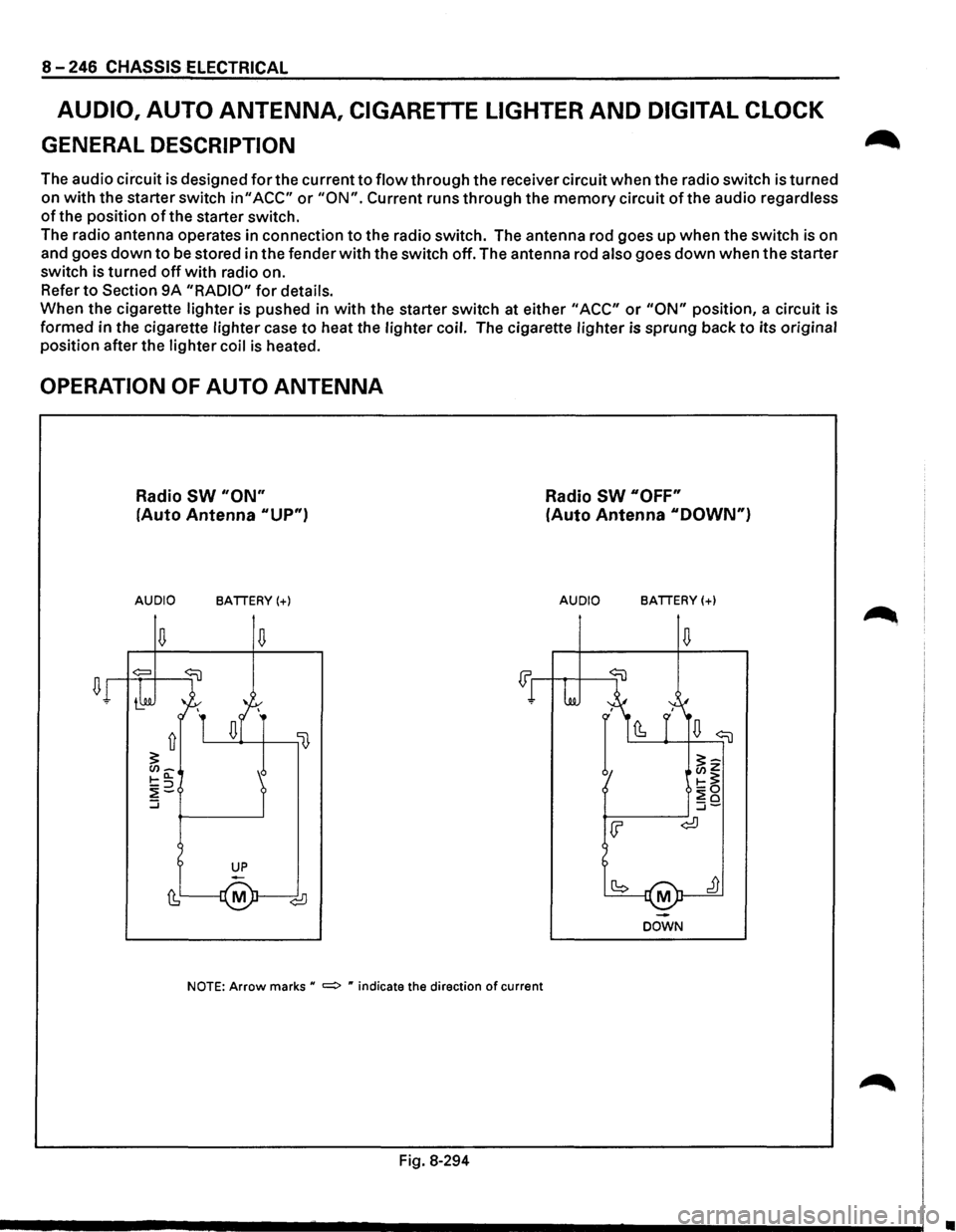
The radio antenna operates in connection
to the radio switch. The antenna rod goes up when the switch is on
and goes
down to be stored in the fender with the switch off. The antenna rod also goes down when the starter
switch is turned
off with radio on.
Refer
to Section 9A "RADIO" for details.
When the cigarette lighter is pushed in
with the starter switch at either "ACC" or "ON" position, a circuit is
formed in the cigarette lighter case
to heat the lighter coil. The cigarette lighter is sprung back to its original
position after the lighter coil
is heated.
OPERATION OF AUTO ANTENNA
Radio SW "ON"
(Auto Antenna "UP")
AUDIO BATTERY(+)
NOTE: Arrow marks u =:> " indicate the direction of current
Fig. 8-294
Radio SW "OFF"
(Auto Antenna "DOWN")
AUDIO BATTERY(+)
M
DOWN
•
Page 1441 of 1928
AUDIO
AUTO ANTENNA
Refer to Section 9A "RADIO" for details.
CIGARETTE LIGHTER
~ INSPECTION
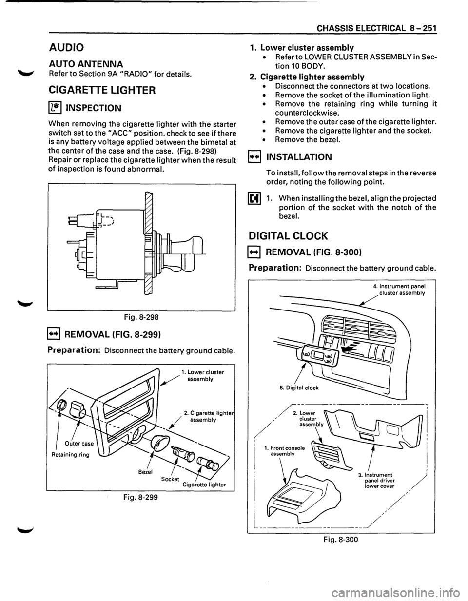
When removing the cigarette lighter with the starter
switch set
to the "ACC" position, check to see if there
is any battery voltage applied between the bimetal at
the center
of the case and the case. (Fig. 8-298)
Repair
or replace the cigarette lighter when the result
of inspection is found abnormal.
Fig. 8-298
B REMOVAL (FIG. 8-299)
Preparation: Disconnect the battery ground cable.
Retaining ring
Fig. 8-299
CHASSIS ELECTRICAL 8-251
1. lower cluster assembly
• Refer to LOWER CLUSTER ASSEMBLY in Sec
tion 10 BODY.
2. Cigarette lighter assembly
• Disconnect the connectors at two locations.
• Remove the socket of the illumination light.
•
Remove the retaining ring while turning it
counterclockwise.
• Remove the outer case of the cigarette lighter.
• Remove the cigarette lighter and the socket.
• Remove the bezel.
I••! INSTALLATION
To install, follow the removal steps in the reverse
order, noting the
following point.
1. When installing the bezel, align the projected
portion
of the socket with the notch of the
bezel.
DIGITAL CLOCK
B REMOVAL (FIG. 8-300)
Preparation: Disconnect the battery ground cable.
Fig.
8-300
4. Instrument panel cluster assembly
Page 1577 of 1928
RADIO 9A-1
ACCESSORIES
Radio .................................................. .
Parts Location ..............................•...........
Circuit Diagram ......•.................................
Antenna ....•......................................•........
Auto Antenna ......................................... .
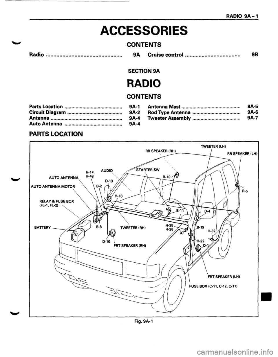
PARTS LOCATION
AUDIO
AUTO ANTENNA
AUTO ANTENNA MOTOR
CONTENTS
9A Cruise control ................................... ..
SECTION 9A
RADIO
CONTENTS
9A-1
9A-2
9A-4
9A-4 Antenna
Mast ........ ~ ................................. .
Rod Type Antenna .................................. .
Tweeter
Assembly .................................. .
lWEETER (LH)
98
9A-5
9A-6
9A·7
RR SPEAKER !RH) ----~ RR SPEAKER (lHl
BATTERY lWEETER (RH)
FRT SPEAKER (LHl
FUSE BOX (C-11, C-12, C-17)
Fig. 9A-1
•
Page 1580 of 1928
9A-4 RADIO
ANTENNA
AUTO ANTENNA
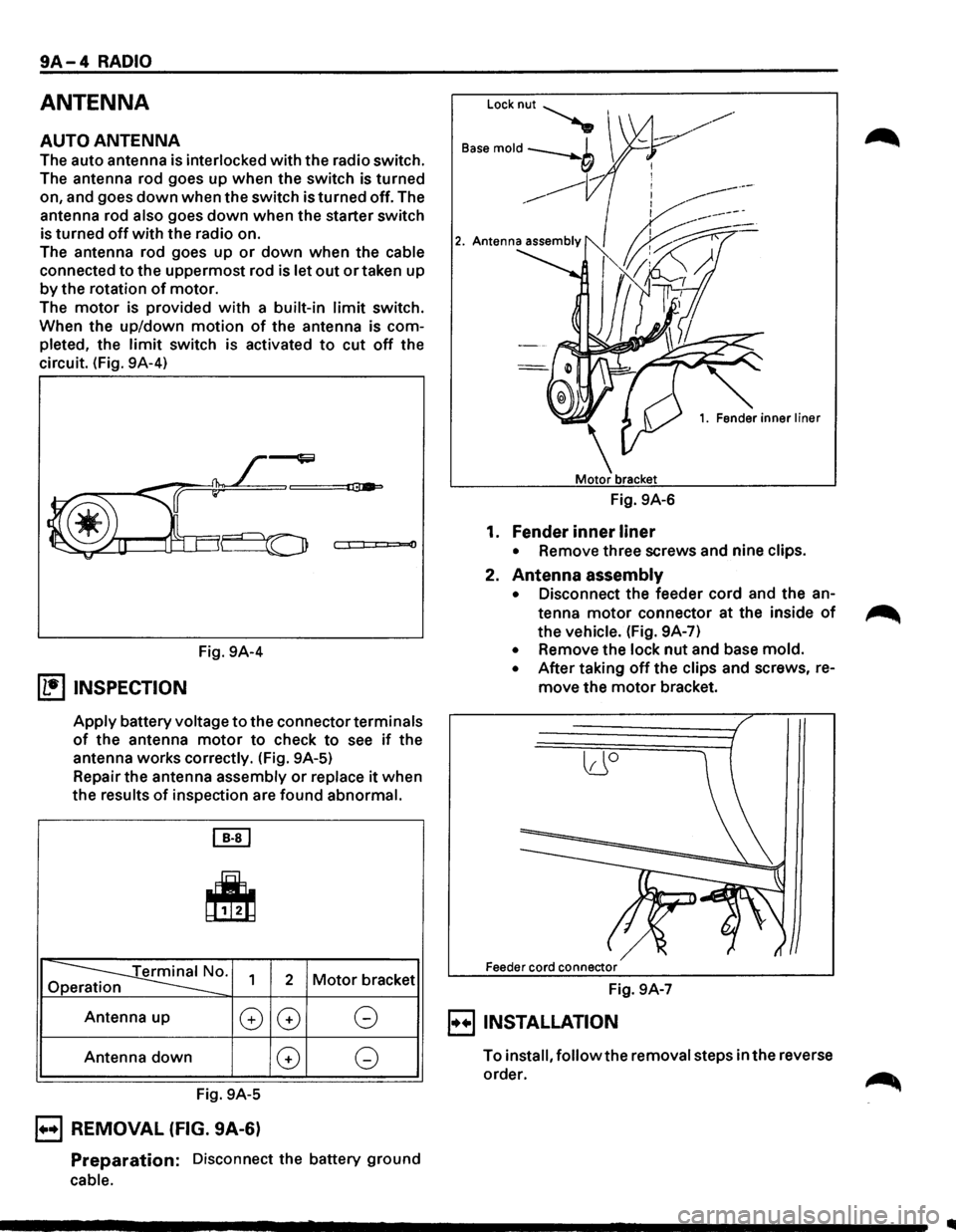
The auto antenna is interlocked with the radio switch.
The antenna rod goes up when the switch is turned
on, and goes
down when the switch is turned off. The
antenna rod
also goes down when the starter switch
is turned
off with the radio on.
The antenna rod goes up
or down when the cable
connected to the uppermost rod is let out or taken up
by the rotation of motor.
The
motor is provided with a built-in limit switch.
When the up/down
motion of the antenna is com
pleted, the
limit switch is activated to cut off the
circuit. (Fig. 9A-4)
0
Fig. 9A-4
(1!] INSPECTION
Apply battery voltage to the connector terminals
of the antenna motor to check to see if the
antenna works correctly. (Fig. 9A-5)
Repair the antenna assembly
or replace it when
the results
of inspection are found abnormal.
[EJ
~
~0. Op 1 2 Motor bracket
Antenna up
G
Antenna down
Fig. 9A-5
B REMOVAL (FIG. 9A-6)
G G
G G
Preparation: Disconnect the battery ground
cable.
Locknut~
B"e mold --b I
___,
------------
1. Fender inner liner
Fig. 9A-6
1. Fender inner liner
• Remove three screws and nine clips.
2. Antenna assembly
• Disconnect the feeder cord and the an
tenna
motor connector at the inside of
the vehicle. (Fig. 9A-7)
• Remove the lock nut and base mold.
• After taking off the clips and screws, re
move the motor bracket.
lJO
Feeder cord connector
Fig. 9A-7
E) INSTALLATION
To install, follow the removal steps in the reverse
order.
Page 1581 of 1928
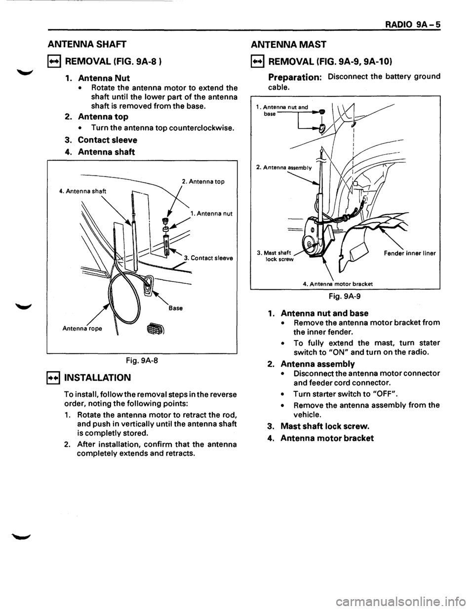
ANTENNA SHAFT
B REMOVAL (FIG. 9A-8 )
1. Antenna Nut
• Rotate the antenna motor to extend the
shaft
until the lower part of the antenna
shaft is removed from the base.
2.
Antenna top
• Turn the antenna top counterclockwise.
3.
Contact sleeve
4. Antenna shaft
Fig. 9A-8
B INSTALLATION
2. Antenna top
Base
To install, follow the removal steps in the reverse
order, noting the
following points:
1. Rotate the antenna motor to retract the rod,
and push in
vertically until the antenna shaft
is
completly stored.
2. After installation, confirm that the antenna
completely extends and retracts.
RADIO 9A-5
ANTENNA MAST
B REMOVAL (FIG. 9A-9, 9A-10)
Preparation: Disconnect the battery ground
cable.
4. Antenna motor brecket
Fig. 9A-9
1.
Antenna nut and base
• Remove the antenna motor bracket from
the inner fender.
• To fully extend the mast, turn stater
switch
to "ON" and turn on the radio.
2.
Antenna assembly
• Disconnect the antenna motor connector
and feeder cord connector.
• Turn starter switch to "OFF".
•
Remove the antenna assembly from the
vehicle.
3. Mast shaft lock screw.
4. Antenna motor bracket
Page 1582 of 1928
9A-6 RADIO
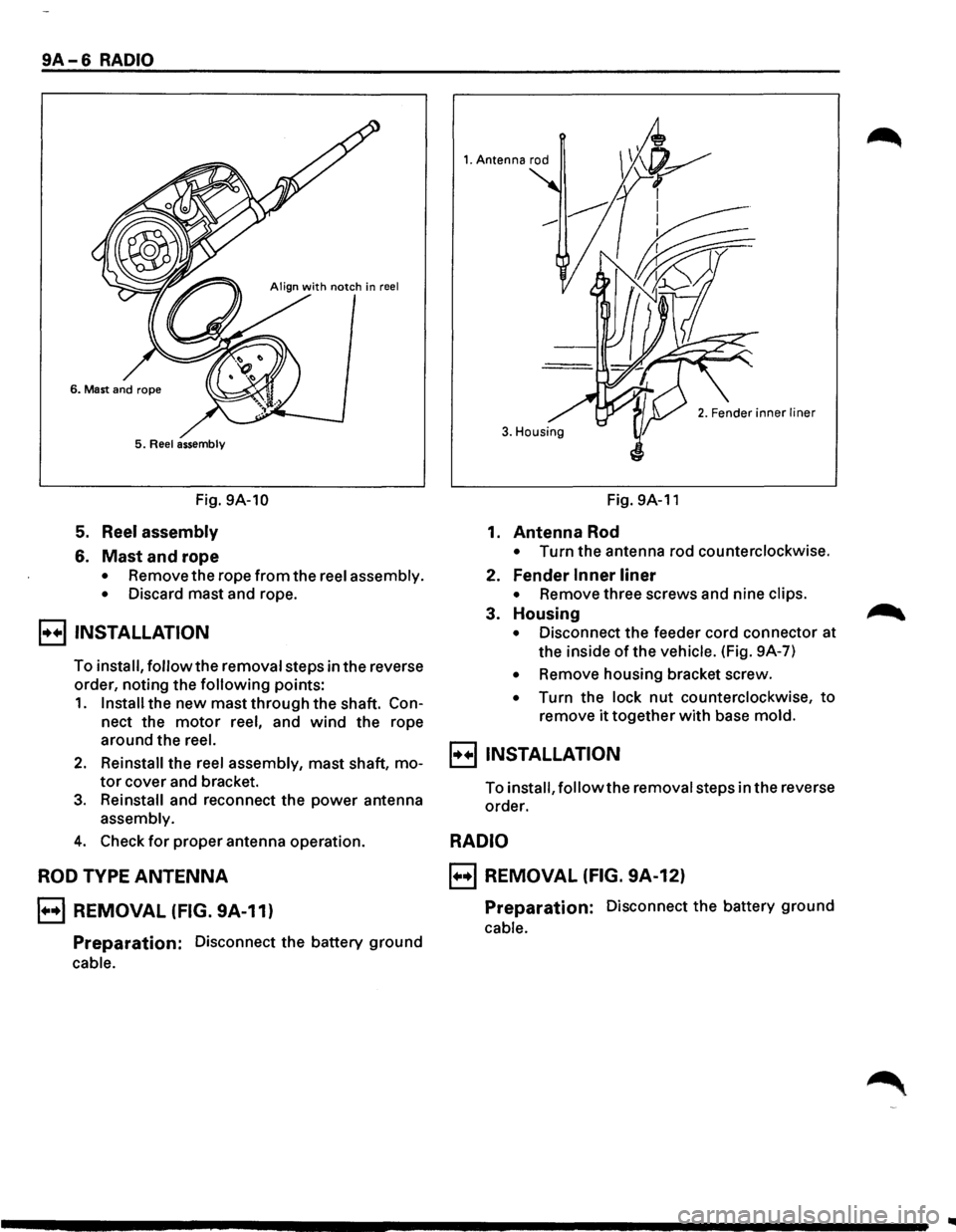
5. Reel assembly
Fig. 9A-10
5. Reel assembly
6. Mast and rope
• Remove the rope from the reel assembly.
•
Discard mast and rope.
B INSTALLATION
To install, follow the removal steps in the reverse
order, noting the
following points:
1. Install the new mast through the shaft. Con
nect the motor reel, and wind the rope
around the
reel.
2. Reinstall the reel assembly, mast shaft, mo
tor cover and bracket.
3. Reinstall and reconnect the power antenna
assembly.
4. Check for proper antenna operation.
ROD TYPE ANTENNA
B REMOVAL (FIG. 9A-11)
Preparation: Disconnect the battery ground
cable.
1. Antenna rod
3. Housing
Fig. 9A-11
1. Antenna Rod
• Turn the antenna rod counterclockwise.
2. Fender Inner liner
• Remove three screws and nine clips.
3. Housing
• Disconnect the feeder cord connector at
the inside
of the vehicle. (Fig. 9A-7)
• Remove housing bracket screw.
• Turn the lock nut counterclockwise, to
remove it together with base mold.
B INSTALLATION
To install, follow the removal steps in the reverse
order.
RADIO
B REMOVAL (FIG. 9A-12)
Preparation: Disconnect the battery ground
cable.
Page 1583 of 1928
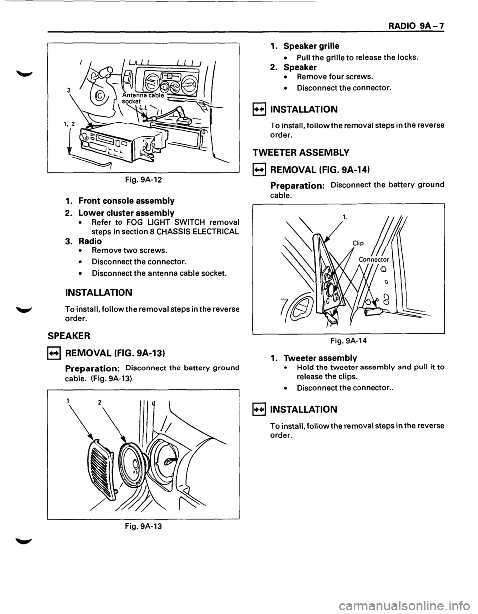
Fig. 9A-12
1. Front console assembly
2. Lower cluster assembly
• Refer to FOG LIGHT SWITCH removal
steps in section 8 CHASSIS ELECTRICAL
3. Radio
• Remove two screws.
• Disconnect the connector.
• Disconnect the antenna cable socket.
INSTALLATION
To install, follow the removal steps in the reverse
order.
SPEAKER
B REMOVAL (FIG. 9A-13)
Preparation: Disconnect the battery ground
cable. (Fig. 9A-13)
Fig. 9A-13
RADIO 9A-7
1. Speaker grille
• Pull the grille to release the locks.
2. Speaker
• Remove four screws.
• Disconnect the connector.
8 INSTALLATION
To install, followthe removal steps in the reverse
order.
TWEETER ASSEMBLY
B REMOVAL (FIG. 9A-14)
Preparation: Disconnect the battery ground
cable.
l. CUp j
Connector
0
Fig. 9A-14
1. Tweeter assembly
• Hold the tweeter assembly and pull it to
release the clips.
•
Disconnect the connector ..
8 INSTALLATION
To install, followthe removal steps in the reverse
order.
Page 1783 of 1928
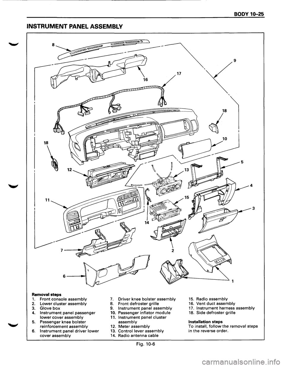
INSTRUMENT PANEL ASSEMBLY
18
11
Removal steps 1. Front console assembly 2. Lower cluster assembly 3. Glove box 4. Instrument panel passenger lower cover assembly
5. Passenger knee bolster reinforcement assembly 6. Instrument panel driver lower cover assembly
7. Driver knee bolster assembly 8. Front defroster grille 9. Instrument panel assembly
10. Passenger inflator module 11. Instrument panel cluster assembly 12. Meter assembly 13. Control lever assembly 14. Radio antenna cable
Fig. 10-6
17
BODY 10-25
9
3
1
15. Radio assembly 16. Vent duct assembly 17. Instrument harness assembly 18. Side defroster grille
Installation steps To install, follow the removal steps
in the reverse order.
Page 1785 of 1928
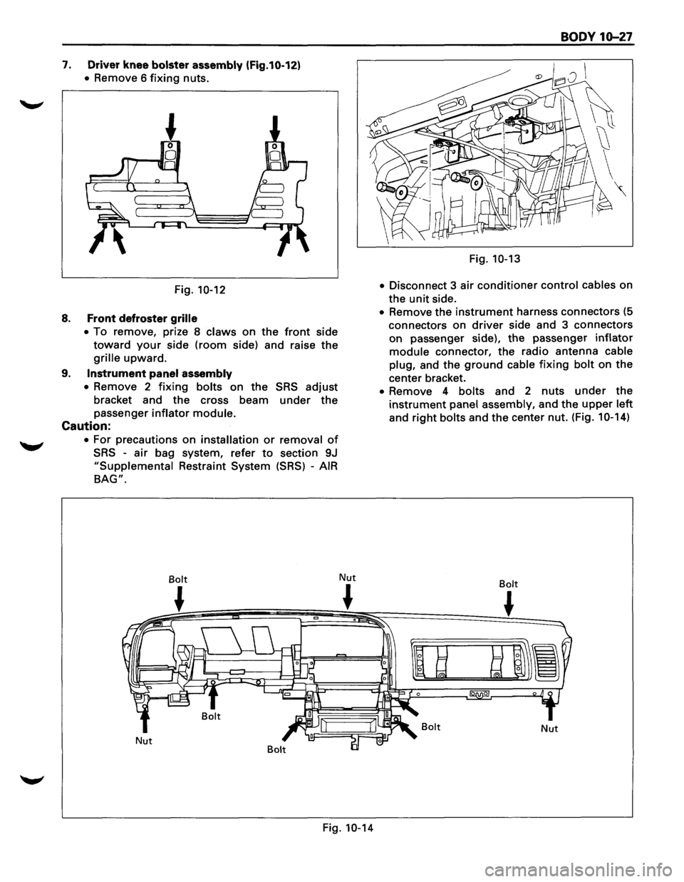
7. Driver knee bolster assembly (Fig.10-12)
• Remove 6 fixing nuts.
Fig.
10-12
8. Front defroster grille
•
To remove, prize 8 claws on the front side
toward your side (room side) and raise the
grille upward.
9. Instrument panel assembly
•
Remove 2 fixing bolts on the SRS adjust
bracket and the cross beam under the
passenger inflator module.
Caution:
• For precautions on installation or removal of
SRS -air bag system, refer to section 9J
"Supplemental Restraint System (SRS) -AIR
BAG".
Bolt
~
Nut Nut
~
Fig. 10-14
BODY 10-27
Fig. 10-13
•
Disconnect 3 air conditioner control cables on
the
unit side.
• Remove the instrument harness connectors (5
connectors on
driver side and 3 connectors
on passenger side), the passenger inflator
module connector, the radio antenna cable
plug,
and the ground cable fixing bolt on the
center bracket.
• Remove 4 bolts and 2 nuts under the
instrument panel assembly, and the upper left
and right bolts and the center nut. (Fig. 1 0-14)
Bolt
~
Bolt Nut
Page 1786 of 1928
10-28 BODY
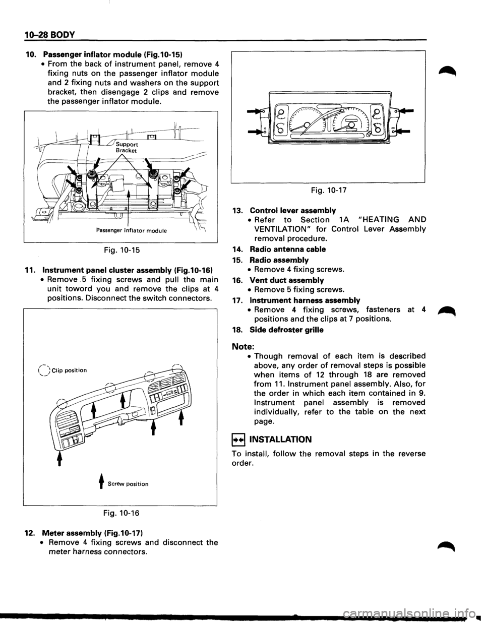
10. Passenger inflator module (Fig.10-15)
• From the back of instrument panel, remove 4
fixing nuts on the passenger inflator module
and 2 fixing nuts and washers on the support
bracket, then disengage 2 clips and remove
the passenger
inflator module.
Passenger inflator module
Fig. 10-15
11. Instrument panel cluster assembly (Fig.10-16)
• Remove . 5 fixing screws and pull the main
unit toward you and remove the clips at 4
positions. Disconnect the switch connectors.
,.-, I ) Clip position --~
t Screw position
Fig. 10-16
12. Meter assembly (Fig.10-17)
• Remove 4 fixing screws and disconnect the
meter harness connectors. Fig.
10-17
13. Control lever
assembly
• Refer to Section 1A "HEATING AND
VENTILATION" for Control Lever Assembly
removal procedure.
14. Radio antenna cable
15. Radio assembly
• Remove 4 fixing screws.
16.
Vent duct assembly
• Remove 5 fixing screws.
17.
Instrument harness assembly
• Remove 4 fixing screws, fasteners at 4 ~
positions and the clips at 7 positions.
18.
Side defroster grille
Note:
• Though removal of each item is described
above, any
order of removal steps is possible
when items of 12 through 18 are removed
from 11. Instrument panel assembly. Also, for
the order in which each item contained in 9.
Instrument panel assembly is removed
individually, refer to the table on the next
page.
I+•IINSTALLATION
To install, follow the removal steps in the reverse
order.
II