fuses ISUZU TROOPER 1995 Workshop Manual
[x] Cancel search | Manufacturer: ISUZU, Model Year: 1995, Model line: TROOPER, Model: ISUZU TROOPER 1995Pages: 1928
Page 375 of 1928
REAR WHEEL ANTILOCK BRAKE SYSTEM 5A3-7
REAR WHEEL ANTILOCK (RWAL) SYSTEM DIAGNOSTICS
DIAGNOSIS PROCEDURE
The RWAL system contains 13 diagnostic trouble
codes
for system troubleshooting. With the ignition
key turned
ON, momentarily grounding the RWAL
diagnostic lead
with the "Rr ABS" light on will cause the
light
to flash out a diagnostic trouble code if a failure
has been detected and is in memory.
Some RWAL
diagnostic trouble codes require a road test in order
to
be set into the EBCM memory.
RWAL diagnostic trouble codes are cleared from
the
EBCM memory every time the ignition key is
turned off. If a diagnostic trouble code is not present, a
test drive
must be performed to reproduce the failure
and reset the code into
memory:
TEST DRIVING
1. Conduct a visual check of the following items to
see if any abnormalities exist:
(a) Service brake mechanism/hydraulic system
(See BRAKE SERVICING SECTION).
(b) Fuses #2, #7, #14 and main fuse
(c) RWAL-related connector (check for loose pins
and rust)
(d) EBCM and valve ground (check for looseness
and rust)
NOTE:
Check
(c) and (d) should be done with ignition key
turned
OFF.
If any abnormality is found, perform repairs as
required.
2. Turn the ignition switch ON. As a self-check, the
"Rr ABS" light should come on for approximately
2 seconds, then go
off and remain off.
If the "Rr ABS" light remains on or comes back
on, check
for diagnostic trouble codes by
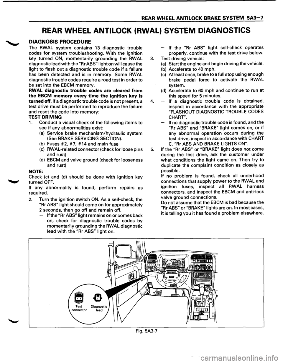
momentarily grounding the RWAL diagnostic
lead
with the "Rr ABS" light on. -
If the "Rr
ABS" light self-check operates
properly, continue
with the test drive below.
3. Test driving vehicle:
(a) Start the engine and begin driving the vehicle.
(b) Accelerate to 40 mph.
(c) At least once, brake to a full stop using enough
brake pedal force
to activate the RWAL
system.
(d) Accelerate to 60 mph and continue to run at
this speed
for 5 minutes.
4. If a diagnostic trouble code is obtained.
inspect in accordance
with the appropriate
"FLASHOUT DIAGNOSTIC TROUBLE CODES
CHART".
If
no diagnostic trouble code is found, and the
"Rr ABS" and "BRAKE" light comes on, or if
any abnormal operation occurs during the
test drive, inspect in accordance
with CHART
C, "Rr ABS AND BRAKE LIGHTS ON".
5. If the "Rr ABS" or "BRAKE" light does not come
during the test drive, ask the customer under
what conditions the light came on. Then try to
duplicate the complaint condition
as closely as
possible.
If no problem is found, check all underhood
connections that supply power
to the RWAL and
ignition fuses, inspect
all RWAL harness
connectors, and inspect the
EBCM and anti-lock
valve ground connections.
Do not assume that the
EBCM is bad because the
"Rr ABS" or "BRAKE" lights are on. In most cases,
it is telling you it has found a problem elsewhere.
Fig. 5A3-7
Page 415 of 1928
4-WHEEL ANTILOCK BRAKE SYSTEM (ABS) 5A4-5
DIAGNOSIS
GENERAL INFORMATION
ABS troubles can be classified to two types, those
which can be detected by the ABS warning light
and those which can be detected as a vehicle
abnormality by the driver.
In either case, locate the fault in accordance with
the "BASIC DIAGNOSTIC FLOWCHART" and repair.
Please refer to Section 5A, 5A1, 5A2, 5C for the
diagnosis
of mechanical troubles such as brake
noise, brake
judder (brake pedal or vehicle vibration
felt when braking), uneven braking, and parking
brake
trouble.
ABS SYSTEM SERVICE PRECAUTIONS
Required Tools and Items
Box Wrench
• Brake Fluid
Special Tool
Some diagnosis procedures in this section require
the installation of a special tool.
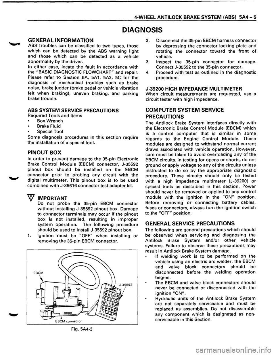
PINOUT BOX
In order to prevent damage to the 35-pin Electronic
Brake
Control Module (EBCM) connector, J-35592
pinout box should be installed on the EBCM
connector prior to probing any circuit with the
digital
multimeter. This pinout box is to be used
combined with J-35616 connector test adapter kit.
W IMPORTANT
Do not probe the 35-pin EBCM connector
without installing J-35592 pinout box. Damage
to connector terminals may occur if the pinout
box is not installed, resulting in improper
system operation. The following procedure
should be used to install J-35592 pinout box.
1. Ignition must be "OFF" when installing or
removing the 35-pin EBCM connector.
Fig. 5A4-3
2. Disconnect the 35-pin EBCM harness connector
by depressing the connector locking plate and
rotating
the connector toward the front of
vehicle.
3. Inspect the 35-pin connector for damage.
Connect J-35592 to the 35-pin connector.
4. Proceed with test as outlined in the diagnostic
procedure.
J-39200 HIGH IMPEDANCE MUL TIMETER
When circuit measurements are requested, use a
circuit tester
with high impedance.
COMPUTER SYSTEM SERVICE
PRECAUTIONS
The Antilock Brake System interfaces directly with
the Electronic Brake Control Module (EBCM) which
is a
control computer that is similar in some
regards
to the Engine Control Module. These
modules are designed to withstand normal current
draws associated with vehicle operation. However,
care
must be taken to avoid overloading any of the
EBCM circuits. In testing for opens or shorts, do not
ground or apply voltage to any of the circuits unless
instructed to
do so by the appropriate diagnostic
procedure. These circuits should only be tested
with a high impedance multimeter (J-39200) or
special tools as described in this section. Power
should never be removed or applied to any control
module with the ignition in the "ON" position.
Before removing
or connecting battery cables,
fuses
or connectors, always turn the ignition switch
to the "OFF" position.
GENERAL SERVICE PRECAUTIONS
The following are general precautions which should
be observed when servicing and diagnosing the
Antilock Brake System and/or
other vehicle
systems. Failure
to observe these precautions may
result in Antilock Brake System damage.
If welding work is to be performed on the
vehicle using an electric arc welder, the EBCM
and valve block connectors should be
disconnected before the
welding operation
begins.
The
EBCM and valve block connectors should
never be connected or disconnected with the
ignition "ON".
Hydraulic units of the Antilock Brake System
are not separately serviceable and must be
replaced
as assemblies. Do not disassemble
any
component which is designated as non
serviceable in
this Section.
Page 440 of 1928
5A4-30 4-WHEEL ANTILOCK BRAKE SYSTEM (ABS)
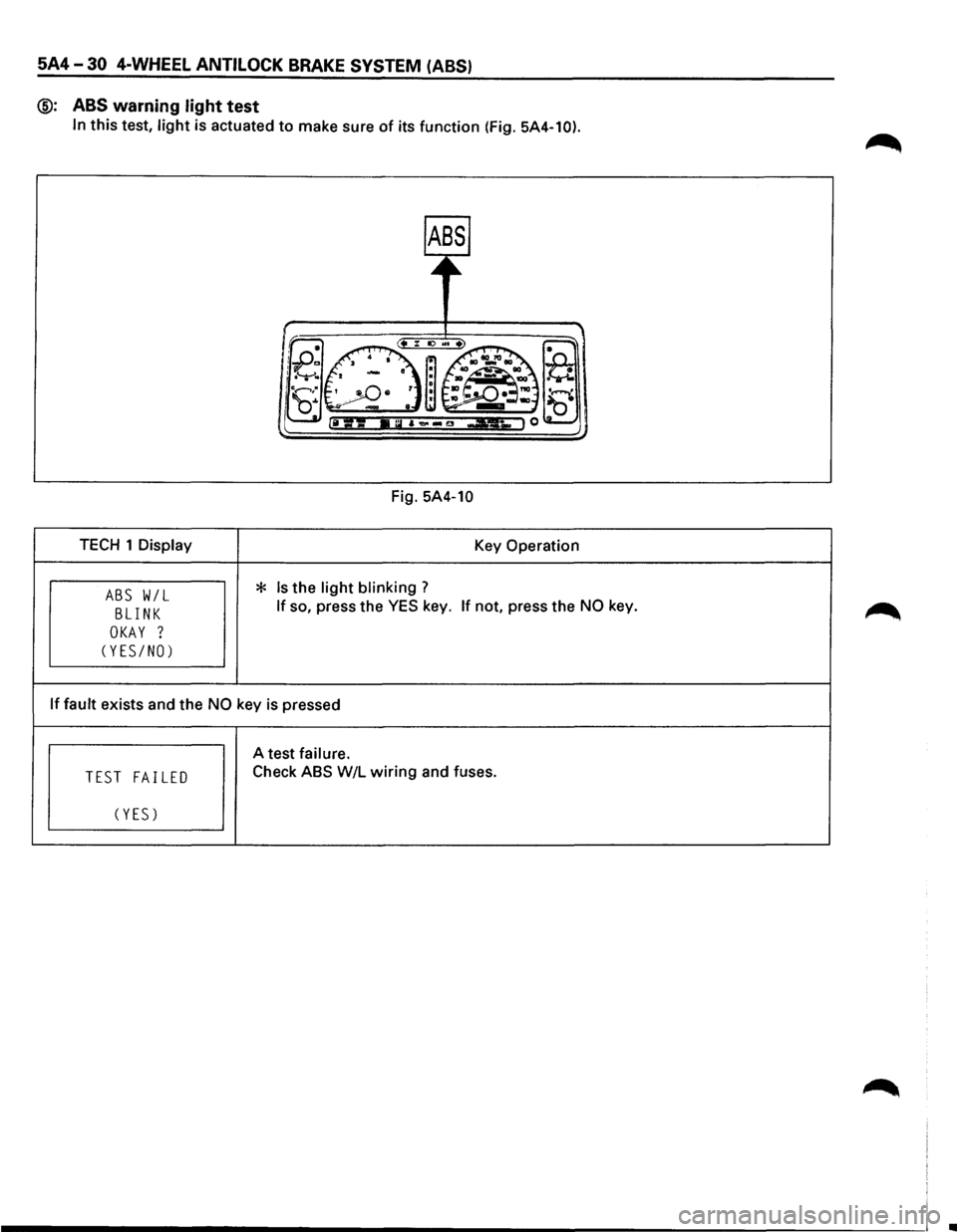
@: ABS
warning light test
In this test, light is actuated to make sure of its function (Fig. 5A4-10).
Fig. 5A4-10
TECH 1 Display
Key Operation
Is the light blinking ? ABS W/L * BLINK If so, press the YES key. If not, press the NO key.
OKAY ?
(YES/NO)
If
fault exists and the NO key is pressed
A test failure.
TEST FAILED Check ABS W/L wiring and
fuses.
(YES)
i _______________________________________________________________________ \
! •
Page 894 of 1928
7 A-22 AUTOMATIC TRANSMISSION (4l30-E)
TEST DRIVING
Some 4L30-E automatic transmission complaints
vehicles will require a test drive as a part of the
diagnostic procedure.
Some codes will not set
unless the vehicle is moving. The purpose of the
test
drive is to duplicate the customer's complaint
condition and set a current Transmission Control
Module (TCM) trouble code. Perform this
procedure before each 4L30-E automatic trans
mission repair, and again after repairs are made.
IMPORTANT:
• Duplicate the condition under which the
customer's complaint was observed.
• Depending on the complaint, line pressure
gauge and the
TECH1 scan tool may be
required
during the test drive.
• During the test drive, it is important to record
all necessary data from the areas being
monitored, for use in diagnosis. Also listen for
and note any unusual noises.
The
following procedure should be used to test
drive 4L30-E automatic
transmission complaint
vehicles:
1. Turn the ignition ON without starting the
engine. Check
that the "CHECK TRANS" lamp
comes on for approximately 2 to 3 seconds
and then goes
out and remains out.
• If the lamp is flashing, GOTO CHECK
TRANS INDICATOR (on page 7A-46).
• If no serial data is present, see Chart 1:
DIAGNOSTIC CONNECTOR AND VOLTAGE
SUPPLY TEST (on page 7A-69 and 7A-70).
• If the lamp stays ON or stays OFF, GOTO
"CHECK TRANS"
CHECK (on page 7A-48).
NOTE:
Remember that, when TECH1 is connected,
line pressure will be at maximum during shifts.
2. Drive the vehicle. During the test drive be sure
that the transmission achieves normal
operating temperature (approx. 20 minutes) ..
Allow the transmission to go through all of 1ts
gear ranges, checking shift timing and
firmness.
Duplicate the owner's complaint
condition as closely as possible during the test
drive.
3. If, during the test drive, the "CHECK TRANS"
lamp comes on, use the TECH1 to check for
trouble codes.
4. If, during the test drive, a problem is felt, but
the "CHECK TRANS" lamp does not come on
and
no trouble codes are present, drive the
vehicle with the TCM disconnected (manually
shifting the vehicle).
•
In Manual L, the vehicle operates in first
gear.
• In Manual 2, the vehicle operates in third
gear.
• In Manual 3 or "D", the vehicle operates in
fourth gear.
If the problem still exists with the TCM
disconnected, refer
to the MECHANICAL/
HYDRAULIC DIAGNOSIS
in this Section.
5. If no problem has been found at this point,
check
all underhood connections that supply
power to the TCM and ignition fuses.
Physically and visually inspect all the TCM
harness connectors
for loose or corroded
terminals. Inspect the TCM ground points.
•
Page 920 of 1928
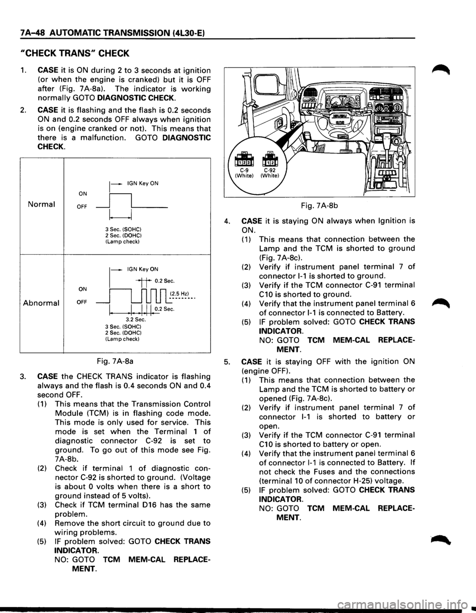
7 A-48 AUTOMATIC TRANSMISSION (4L30-E)
"CHECK TRANS" CHECK
1. CASE it is ON during 2 to 3 seconds at ignition
(or when the engine is cranked) but it is OFF
after (Fig. 7A-8a). The indicator is working
normally GOTO DIAGNOSTIC CHECK.
2. CASE it is flashing and the flash is 0.2 seconds
ON and 0.2 seconds OFF always when ignition
is on (engine cranked or not). This means that
there is a malfunction. GOTO DIAGNOSTIC
CHECK.
Normal
Abnormal
~-IGN Key ON
ON
II
OFF __j l___
~
3 Sec. (SOHC) 2 Sec. (OOHC) (Lamp check)
1-
IGN Key ON
il 0.2Sec.
oN 11 n n n ~~--s_ ~~)-_. OFF __j u u u l:
I. .I. .1.11. 0.2
Sec.
3.2 Sec. 3 Sec. (SOHC) 2 Sec. (OOHC) (Lamp check)
Fig. 7A-8b
4. CASE it is staying ON always when Ignition is
ON.
(1) This means that connection between the
Lamp and the TCM is shorted to ground
(Fig. 7 A-8c).
(2) Verify if instrument panel terminal 7 of
connector 1-1 is shorted to ground.
(3) Verify if the TCM connector C-91 terminal
C10 is shorted to ground.
(4) Verify that the instrument panel terminal 6
of connector 1-1 is connected to Battery.
(5) IF problem solved: GOTO CHECK TRANS
INDICATOR.
NO: GOTO TCM MEM-CAL REPLACE
MENT.
Fig. 7A-8a 5. CASE it is staying OFF with the ignition ON
(engine OFF). 3. CASE the CHECK TRANS indicator is flashing
always and the flash is 0.4 seconds ON and 0.4
second OFF.
(1) This means that the Transmission Control
Module (TCM) is in flashing code mode.
This mode is only used for service. This
mode is set when the Terminal 1 of
diagnostic connector C-92 is set to
ground. To go out of this mode see Fig.
7A-8b.
(2) Check
if terminal 1 of diagnostic con
nector C-92 is shorted to ground. (Voltage
is
about 0 volts when there is a short to
ground instead of 5 volts).
(3) Check if TCM terminal 016 has the same
problem.
(4) Remove the short circuit to ground due to
wiring problems.
(5) IF problem solved: GOTO CHECK TRANS
INDICATOR.
NO: GOTO TCM MEM-CAL REPLACE
MENT.
(1) This means that connection between the
Lamp and the TCM is shorted to battery or
opened (Fig. 7 A-8c).
(2) Verify if instrument panel terminal 7 of
connector 1-1 is shorted to battery or
open.
(3)
Verify if the TCM connector C-91 terminal
C1 0 is shorted to battery or open.
(4)
Verify that the instrument panel terminal 6
of connector 1-1 is connected to Battery. If
not check the Fuses and the connections
(terminal 10 of connector H-25) voltage.
(5) IF problem solved: GOTO CHECK TRANS
INDICATOR.
NO: GOTO TCM MEM-CAL REPLACE
MENT.
Page 1201 of 1928
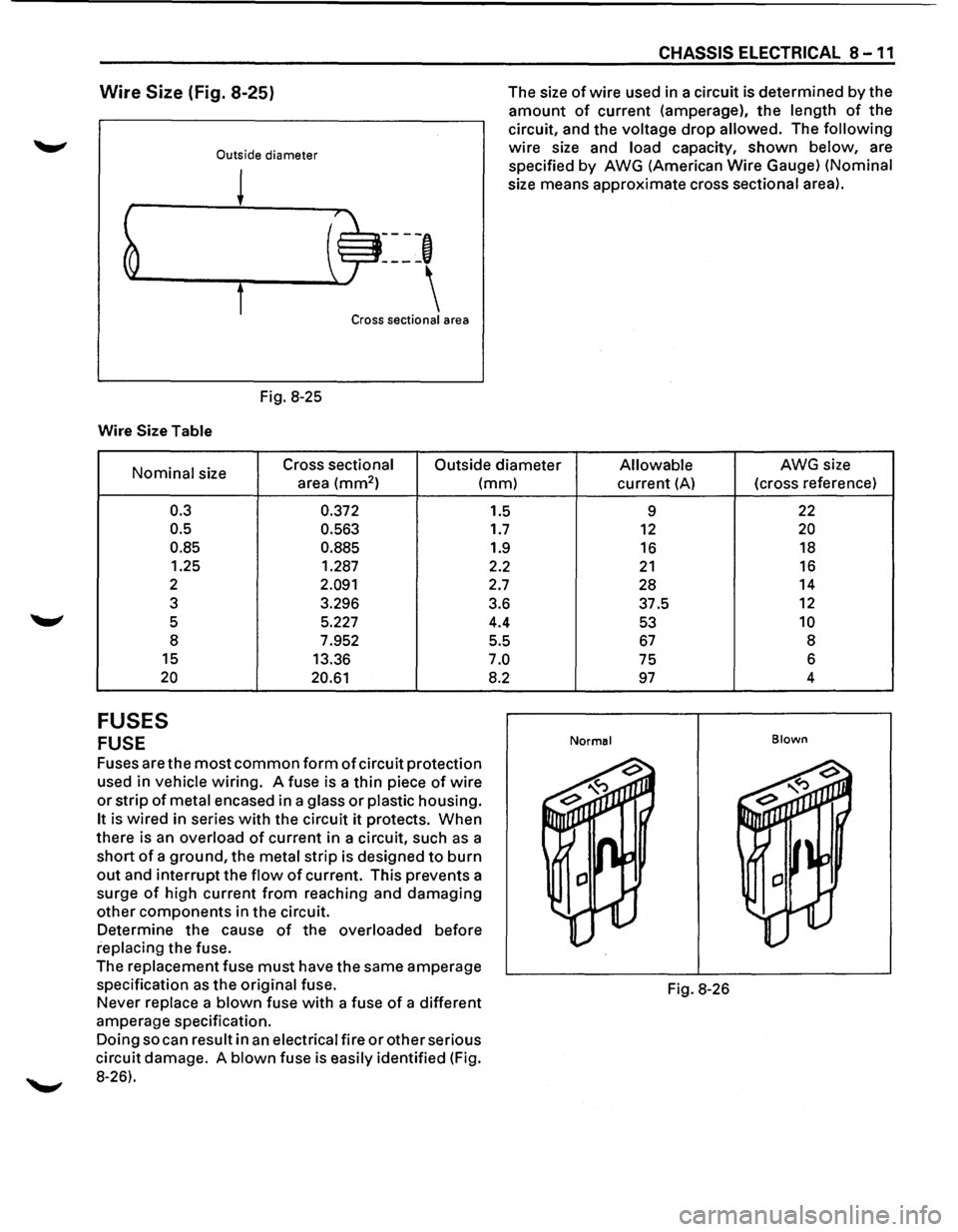
Wire Size (Fig. 8-25)
Outside diameter
Fig. 8-25
Wire Size Table
----,
Cross sectional area
CHASSIS ELECTRICAL 8 -11
The size of wire used in a circuit is determined by the
amount of current (amperage), the length of the
circuit, and the voltage drop allowed. The following
wire size and load capacity, shown below, are
specified
by AWG (American Wire Gauge) (Nominal
size means approximate cross sectional area).
Nominal size Cross sectional
Outside diameter Allowable AWG size
area
(mm2 ) (mm)
0.3
0.5
0.85
1.25
2
3
5 8
15
20
FUSES
FUSE
0.372
0.563
0.885
1.287
2.091
3.296
5.227
7.952
13.36
20.61
Fuses are the most common form of circuit protection
used in vehicle wiring. A fuse is a thin piece of wire
or strip of metal encased in a glass or plastic housing.
It is wired in series with the circuit it protects. When
there is an overload of current in a circuit, such as a
short of a ground, the metal strip is designed to burn
out and interrupt the flow of current. This prevents a
surge
of high current from reaching and damaging
other components in the circuit.
Determine the cause of the overloaded before
replacing the fuse.
The
replacement fuse must have the same amperage
specification as the original fuse.
Never replace a blown fuse with a fuse of a different
amperage specification.
Doing so can result in an electrical fire or other serious
circuit damage. A blown fuse is easily identified (Fig.
8-26). 1.5
1.7
1.9
2.2
2.7
3.6 4.4
5.5
7.0
8.2
current (A) (cross
reference)
9
22
12 20
16 18
21 16
28 14
37.5
12
53 10
67 8
75 6
97 4
Normal Blown
Fig.
8-26
Page 1289 of 1928
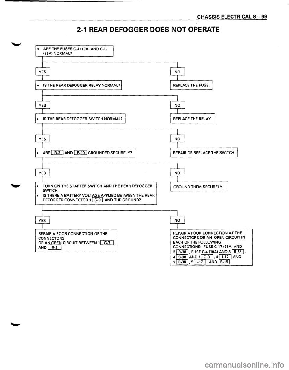
CHASSIS ELECTRICAL 8 -99
2-1 REAR DEFOGGER DOES NOT OPERATE
• ARE THE FUSES C-4 (10Al AND C-17
I (25Al NORMAL?
I
I
YES I NO l
I
• IS THE REAR DEFOGGER RELAY NORMAL? REPLACE THE FUSE. I
I
I
YES I NO I
1
• IS THE REAR DEFOGGER SWITCH NORMAL? I REPLACE THE RELAY I
I
I
YES I NO I
I
• ARE WJ AND ~GROUNDED SECURELY? I REPAIR OR REPLACE THE SWITCH.l
I
I
YES I NO I
I
• TURN ON THE STARTER SWITCH AND THE REAR DEFOGGER
GROUND THEM SECURELY. I SWITCH.
• IS THERE A BATIERY VOLTAGE APPLIED BETWEEN THE REAR DEFOGGER CONNECTOR 1 ~ AND THE GROUND?
I
I
YES I NO l
I
REPAIR A POOR CONNECTION OF THE REPAIR A POOR CONNECTION AT THE
CONNECTORS CONNECTORS OR AN OPEN
CIRCUIT IN
OR AN OPEN CIRCUIT BETWEEN 1[]TI EACH OF THE FOLLOWING
AND[BTI CONNECTIONS: FUSE C-17 (25Al AND
2 I B-38 • FUSE C-4 (10Al AND 31 B-38 I.
4
1B-38 AN~,4~AND 1 ~ , 5 1-17 AND B-19
.
Page 1660 of 1928
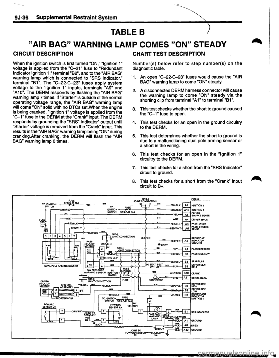
9J-36 Supplemental Restraint System
TABLE B
"AIR BAG" WARNING LAMP COMES "ON" STEADY
CIRCUIT DESCRIPTION
When the ignition switch is first turned "ON," "Ignition 1"
voltage is applied from the "C-21" fuse to "Redundant
Indicator Ignition 1 ,"terminal "B2", and to the "AIR BAG"
warning lamp which is connected to "SRS Indicator,"
terminal "B1". The "C-22·C-23" fuses apply system
voltage to the
"Ignition 1" inputs, terminals "A9" and
"A10". The DERM responds by flashing the "AIR BAG"
warning lamp 7 times. If "Starter" is outside of the normal
operating voltage range, the
"AIR BAG" warning lamp
will
come "ON" solid with no DTCs set. When the engine
is being cranked,
"Ignition 1" voltage is applied from the
"C-1" fuse to the DERM at the "Crank" input. The DERM
responds by grounding the
"SRS" Indicator" output until
"Starter" voltage is removed from the "Crank'' input. This
results in the
"AIR BAG" warning lamp being "ON" during
cranking.After cranking, the DERM
will flash the "AIR
BAG" warning lamp 6 times.
CHART TEST DESCRIPTION
Number(s) below refer to step number(s) on the
diagnostic table.
1. An open "C-22-C-23" fuses would cause the "AIR
BAG" warning lamp to come "ON" steady.
2. A disconnected DERM harness connector will cause
the warning
lamp to come "ON" steady via the
shorting clip from terminal "A1" to terminal "81".
3. This test checks whether the short to ground caused
the
"C-1" fuse to open.
4. This test checks for an open in the ground circuitry
to the DERM.
5. This test determines whether the short to ground is
due to a malfunctioning dual pole arming sensor or
a short
in the wiring.
6. This test checks for an open in the "Ignition 1"
circuitry to the DERM.
7. This test checks for a short from the "SRS Indicator''
circuit to ground.
8. This test checks for a short from the "Crank" input
circuit to 8+.
SRS-1 JOINT CONNECTION TO IGNITION FUSE SRS C·23 10A 1!015 '12 10 IGNITION I IGNITION 1 SWITCH
FUSE~ SRS C-24 10A .... R D
PASS.3eVLR PASS. SOURCE SENSE
PASS SlOE HIGH
PASS SlOE LOW
SERIAL DATA
SRS INDICATOR
..
Page 1662 of 1928
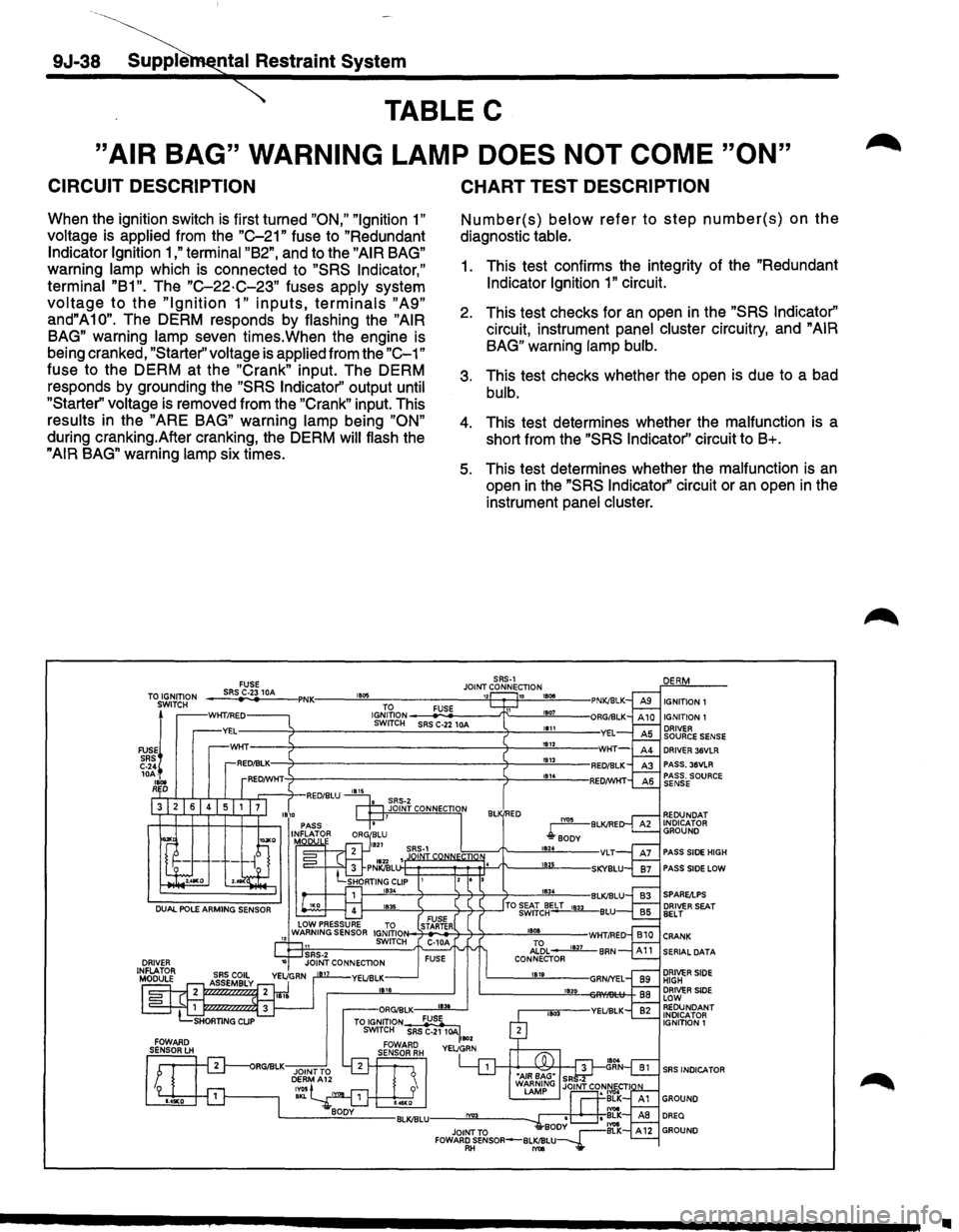
9J-38-~tal Restraint System
TABLE C
"AIR BAG" WARNING LAMP DOES NOT COME "ON"
CIRCUIT DESCRIPTION
When the ignition switch is first turned "ON," "Ignition 1"
voltage is applied from the "C-21" fuse to "Redundant
Indicator Ignition 1 ,"terminal "B2", and to the "AIR BAG"
warning lamp which is connected to "SRS Indicator,"
terminal "B1".
The "C-22·C-23" fuses apply system
voltage to the "Ignition 1" inputs, terminals "A9"
and"A10". The DERM responds by flashing the "AIR
BAG"
warning lamp seven times.When the engine is
being cranked,
"Starter'' voltage is applied from the "C-1"
fuse to the DERM at the "Crank" input. The DERM
responds by grounding the
"SRS Indicator'' output until
"Starter" voltage
is removed from the "Crank" input. This
results in the "ARE BAG" warning lamp being "ON"
during cranking.After cranking, the DERM will flash the
"AIR BAG" warning lamp six times.
TO IGNITION
SWITCH
FUSEj
SRS C-24 10A-
1Bot RD
FUSE SRS C-23 10A ,. ..
CHART TEST DESCRIPTION
Number(s) below refer to step number(s) on the
diagnostic table.
1. This test confirms the integrity of the "Redundant
Indicator Ignition 1" circuit.
2. This test checks for an open in the "SRS Indicator"
circuit, instrument panel cluster circuitry, and "AIR
BAG"
warning lamp bulb.
3. This test checks whether the open is due to a bad
bulb.
4. This test determines whether the malfunction is a
short from the
"SRS Indicator'' circuit to B+.
5. This test determines whether the malfunction is an
open in the "SRS Indicator'' circuit or an open in the
instrument
panel cluster.
SRS-1 JOINT CONNECTION
1834
IGNITION 1 IGNITION 1 DRIVER SOURCE SENSE DRIVER 36VLR PASS. 36VLR
REDUNDAT
INDICATOR GROUND
PASS
SIDE HIGH
PASS
SIDE LOW
1---''""""'-------'l-----l--'1-~--'TO ~&'Jc~ELT 1833 BLU FUSE N-7-ST.,AR_TE.,_R+-'l---'1----"''"'"'-"---WHT/RED C-1 0A Al'6L ____.Jill_ BAN FUSE CONNECTOR 1819
1820
SERIAL DATA
DRIVER SIDE HIGH DRIVER SIDE LOW REDUNDANT INDICATOR
IGNITION 1
SRS INDICA TOR
•
Page 1664 of 1928
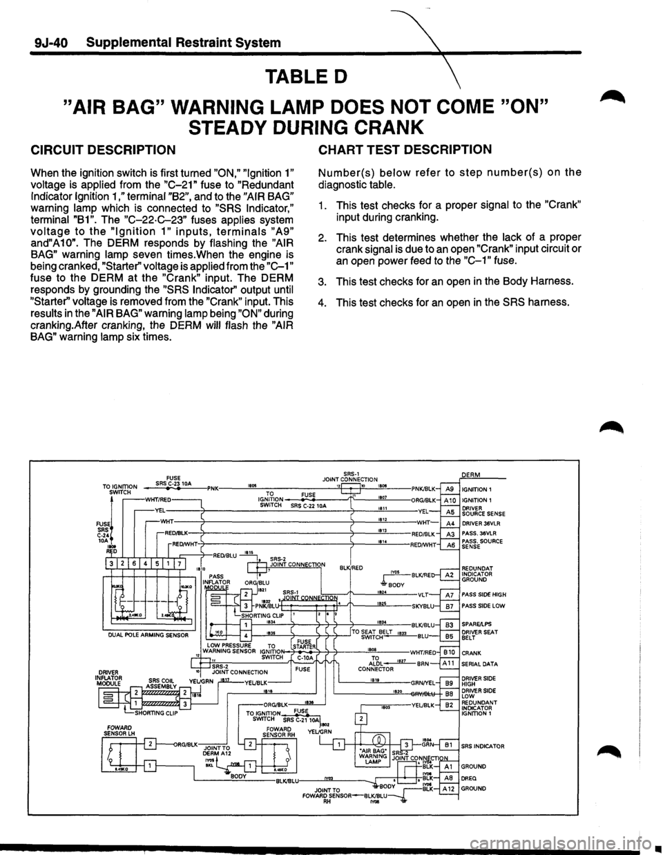
9J-40 Supplemental Restraint System
TABLED
"AIR BAG" WARNING LAMP DOES NOT COME "ON"
STEADY DURING
CRANK
CIRCUIT DESCRIPTION
When the ignition switch is first turned "ON," "Ignition 1"
voltage is applied from the "C-21" fuse to "Redundant
Indicator Ignition
1 ,"terminal "B2", and to the "AIR BAG"
warning lamp which is connected to "SRS Indicator,"
terminal "B1". The "C-22-C-23" fuses applies system
voltage to the "Ignition 1" inputs, terminals "A9"
and"A10". The DERM responds by flashing the "AIR
BAG"
warning lamp seven times.When the engine is
being cranked,
"Starter'' voltage is applied from the "C-1"
fuse to the DERM at the "Crank" input. The DERM
responds by grounding the
"SRS Indicator'' output until
"Starter'' voltage is removed from the "Crank" input. This
results
in the "AIR BAG" warning lamp being "ON" during
cranking.After cranking, the DERM
will flash the "AIR
BAG"
warning lamp six times.
FUSE
CHART TEST DESCRIPTION
Number(s) below refer to step number(s) on the
diagnostic table.
1. This test checks for a proper signal to the "Crank"
input during cranking.
2. This test determines whether the lack of a proper
crank signal
is due to an open "Crank" input circuit or
an open power feed to the "C-1" fuse.
3. This test checks for an open in the Body Harness.
4. This test checks for an open in the SRS harness.
SRS-1
TO IGNITION SWITCH
JOINT CONNECTION ___ sR_S~C-·23~1-~---PNK.----~"~~------------~~~--~~~~---IGNITION1
IGNITION 1
FUSE~ SRS C-24 lOA loot R D
IGJ;~ION __ __.,;FU.:;.SE0------'!"------"'""""---------:1-----------S-W_IT_CH ___ SR_S_C-_22_1_DA ____ -7-----"'a"-'"-----YEL
IYOS BLK/RE
l"soDv
DRIVER 36VLR PASS. 36VLA PASS. SOURCE SENSE
REDUNDAT INDICATOR GROUND
PASS SIDE HIGH
PASS SIDE LOW
SERIAL DATA
DRIVER SIDE HIGH DRIVER SIDE LOW REDUNDANT INDICATOR IGNITION 1
SRS INDICATOR
•