ground clearance ISUZU TROOPER 1995 Workshop Manual
[x] Cancel search | Manufacturer: ISUZU, Model Year: 1995, Model line: TROOPER, Model: ISUZU TROOPER 1995Pages: 1928
Page 49 of 1928
HEATING AND VENTILATION 1A-19
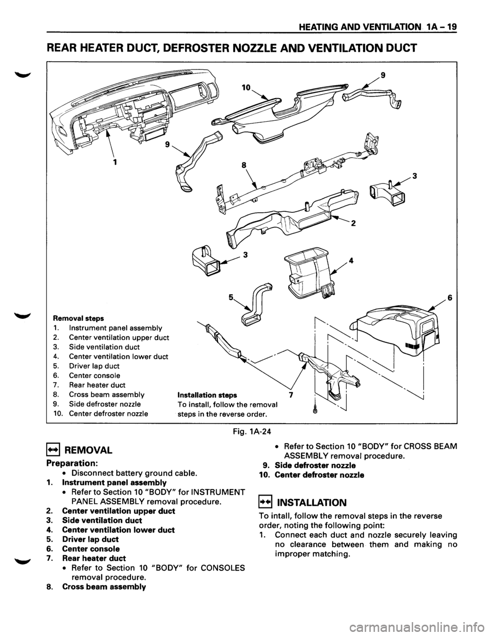
REAR HEATER DUCT, DEFROSTER NOZZLE AND VENTILATION DUCT
6
Removal steps
1. Instrument panel assembly
2. Center ventilation upper duct
3. Side ventilation duct
4. Center ventilation lower duct
5. Driver lap duct
6. Center console
7. Rear heater duct
8. Cross beam assembly Installation steps
9. Side defroster nozzle
10. Center defroster nozzle
To install, follow the removal
steps in the reverse order.
Fig. 1A-24
B REMOVAL
Preparation:
• Disconnect battery ground cable.
1. Instrument panel assembly
• Refer to Section 10 "BODY" for INSTRUMENT
PANEL ASSEMBLY removal procedure.
2. Center ventilation upper duct
3. Side ventilation duct
4. Center ventilation lower duct
5. Driver lap duct
6. Center console
7. Rear heater duct
• Refer to Section 10 "BODY" for CONSOLES
removal
procedure.
8. Cross beam assembly
• Refer to Section 10 "BODY" for CROSS BEAM
ASSEMBLY
removal procedure.
9. Side defroster nozzle
10. Center defroster nozzle
~!!) INSTALLATION
To intall, follow the removal steps in the reverse
order,
noting the following point:
1. Connect each duct and nozzle securely leaving
no clearance between them and making no
improper matching.
Page 201 of 1928
WHEELS AND TIRES 3E-1
SECTION 3E
WHEELS AND TIRES
W CAUTION:
When fasteners are removed, always reinstall them at the same location from which they were removed.
If a fastener needs to be replaced, use the correct part number fastener for that application. If the correct
part
number fastener is not available, a fastener of equal size and strength (or stronger) may be used.
Fasteners
that are not reused, and those requiring thread locking compound, will be called out. The correct
torque value must be used when installing fasteners that require it. If the above conditions are not
followed, parts or system damage could result.
CONTENTS
General Description . . . . . . . . . . . . . . . . . . . . . . . . . . . . . . . 3 E -1 Unit Repair .......................................... 3E-7
Diagnosis ........................................... 3E-2 Tires ............................................... 3E-7
Irregular and Premature Wear ................ 3E-2 Wheels ............................................ 3E-7
Inflation of Tires ................................. 3 E- 3 General Balance Procedure ................... 3E-8
Diagnosis List. . . . . . . . . . . . . . . . . . . . . . . . . . . . . . . . . . . . 3 E- 3 Balancing Wheel and Tire ...................... 3E-8
On-Vehicle Service ................................ 3E-6 Main Data and Specifications .................... 3E-9
Wheels ............................................ 3E-6 General Specifications ......................... 3E-9
Torque Specifications .......................... 3E-9
GENERAL DESCRIPTION
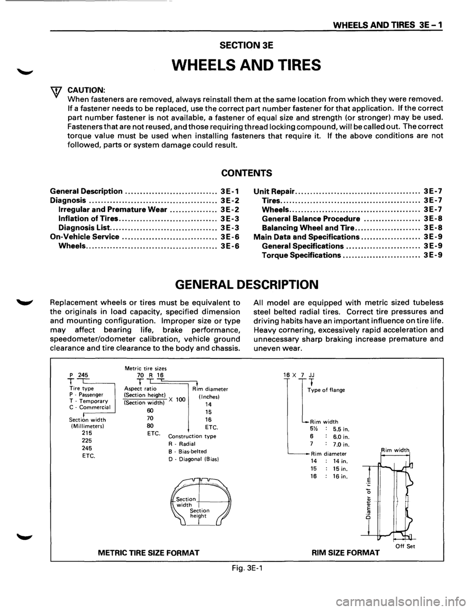
Replacement wheels or tires must be equivalent to
the originals in load capacity, specified dimension
and mounting configuration. Improper size or type
may affect bearing life, brake performance,
speedometer/odometer calibration, vehicle ground
clearance and tire clearance to the body and chassis.
p 245
T Tire type P -Passenger T -Temporary C -Commercial
Section
width (Millimeters) 215 225
245
ETC.
Metric tire sizes 70 R 16 T ,...
Aspect ratio I Rim diameter
(Section height)
(Section
width) X 100 (Inches)
14 60 70
80 ETC.
15
16 ETC.
Construction type
R-Radial
B - Bias-belted
D - Diagonal (Bias)
METRIC TIRE SIZE FORMAT
All model are equipped with metric sized tubeless
steel belted radial
tires. Correct tire pressures and
driving habits have an important influence on tire life.
Heavy cornering, excessively rapid acceleration and
unnecessary sharp braking increase
premature and
uneven wear.
16 X 7 JJ
I
~pe of flange
Rim width 5% 5.5 in.
6 6.0 in. 7 7.0 in.
Rim diameter Rim width
14 14 in. 15 15 in. 16 : 16 in.
I Off Set RIM SIZE FORMAT
Fig. 3E-1
Page 500 of 1928
6-2 ENGINE DIAGNOSIS
SECTION 6E-DRIVEABILITY
AND EMISSIONS
This section covers emission control systems general
information, and diagnostic procedures which will lead
to repairing performance and driveability related
problems.
Emission components are covered, as well
as removal and replacement procedures.
Instructions on use
of special tools are also given.
SECTION 6F-ENGINE EXHAUST
This section has information on all exhaust system
parts, such
as tailpipes, mufflers, and the catalytic
converter.
GENERAL DESCRIPTION
ENGINE CLEANLINESS AND CARE
An automobile engine is a combination of many
machined, honed,
polished and lapped surfaces with
tolerances that are measured in the thousandths of a
millimeter (ten thousandths of an inch). Accordingly,
when any
internal engine parts are serviced, care and
cleanliness are important. Throughout this section, it
should be understood that proper cleaning and
protection
of machined surfaces and friction areas is
part
of the repair procedure. This is considered
standard shop practice even
if not specifically stated.
• A liberal coating of engine oil should be applied to
all friction areas during assembly to protect and
lubricate the surfaces on initial operation.
• Whenever valve train components, pistons, piston
rings, connecting rods, rod bearings, and
crankshaft
journal bearings are removed for
service, they should be retained in order.
• At the time of installation, they should be installed
in the same locations and with the same mating
surfaces
as when removed.
• Battery cables should be disconnected before any
major
work is performed on the engine. Failure to
disconnect
cables may result in damage to wire
harness
or other electrical parts.
• The six cylinders of this engine are identified by
numbers; Right side
cylinders 1, 3 and 5, Left side
cylinders 2, 4 and 6, as counted from crankshaft
pulley side to flywheel side.
GENERAL INFORMATION ON ENGINE
SERVICE
The following information on engine service should be
noted
carefully, as it is important in preventing damage
and contributing
to reliable engine performance.
• When raising or supporting the engine for any
reason,
do not use a jack under the oil pan. Due to
the
small clearance between the oil pan and the oil
pump strainer, jacking against the oil pan may
cause damage to the
oil pick-up unit.
• The 12-volt electrical system is capable of
damaging circuits. When performing any work
where electrical terminals could possibly be
grounded, the ground cable of the battery should
be disconnected at the battery.
• Any time the intake air duct or air cleaner is
removed, the intake opening
should be covered.
This
will protect against accidental entrance of
foreign material into the cylinder which could
cause extensive damage when the engine is
started.
ENGINE DIAGNOSIS
CONTENTS
Hard Starting . . . . . . . . . . . . . . . . . . . . . . . . . 6-3
Engine Compression
Test Procedure ..... 6-4
Rough Engine
Idling or Engine Stalling . . . 6-5
Rough Engine Running . . . . . . . . . . . . . . . . .
6-6
Hesitation . . . . . . . . . . . . . . . . . . . . . . . . . . . . 6-7
Engine Lacks
Power . . . . . . . . . . . . . . . . . . . . 6-8
Engine
Noisy .......................... 6-10
Abnormal Combustion . . . . . . . . . . . . . . . . . . 6-12
Engine Oil Consumption Excessive . . . . . . . 6-13
Fuel Consumption Excessive ............. 6-14
Oil Problems . . . . . . . . . . . . . . . . . . . . . . . . . . 6-14
Malfunction Indicator Lamp . . . . . . . . . . . . . . 6-15
Engine Oil Pressure Check ............... 6-16
Inspection of Hydraulic Lash Adjuster . . . . . 6-17
Page 1809 of 1928
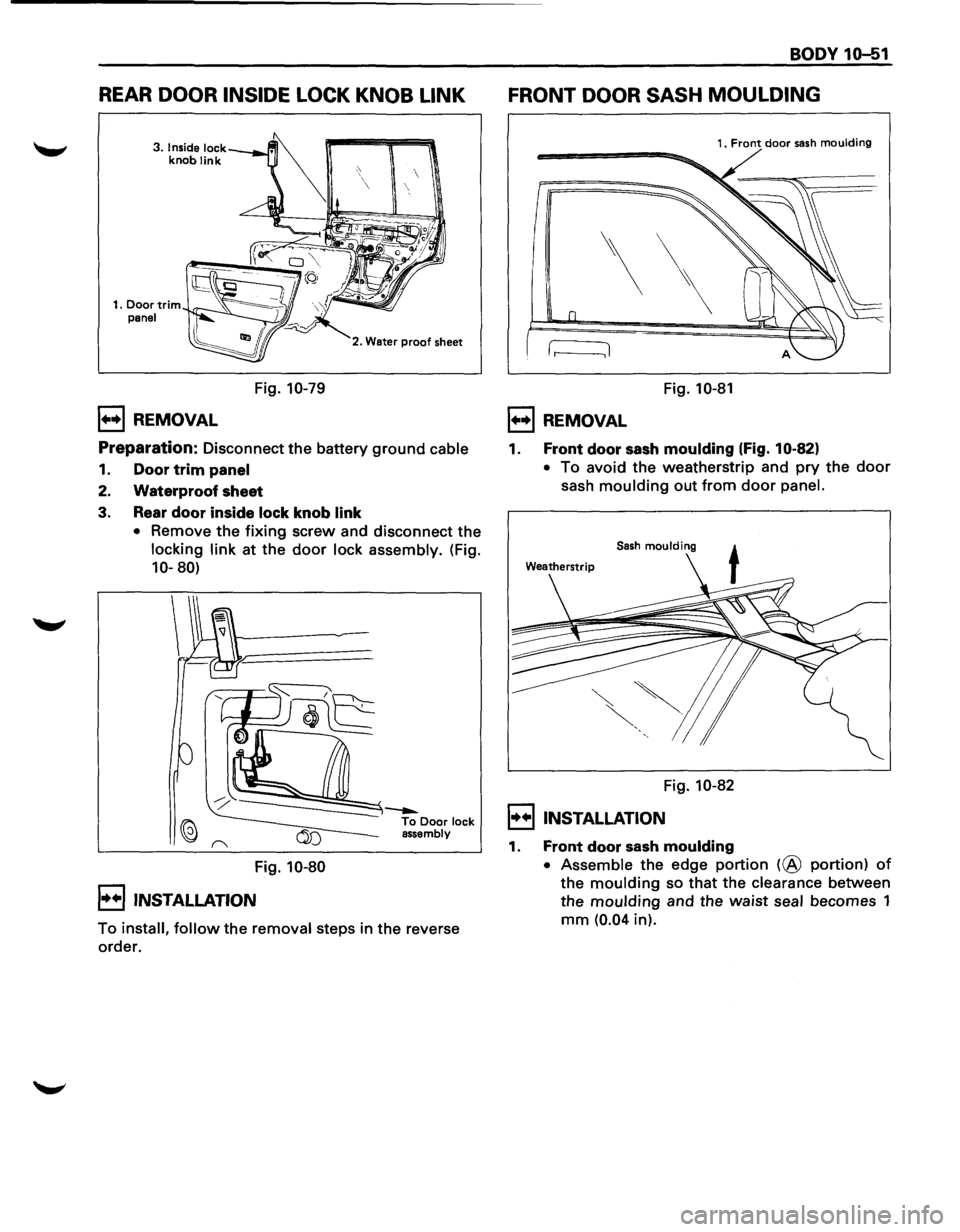
REAR DOOR INSIDE LOCK KNOB LINK
3. Inside lock knob link
1••1 REMOVAL
Fig. 10-79
2. Water proof sheet
Preparation: Disconnect the battery ground cable
1. Door trim panel
2. Waterproof sheet
3. Rear door inside lock knob link
• Remove the fixing screw and disconnect the
locking link at the door lock assembly. (Fig.
10-80)
Fig. 10-80
I••IINSTALLATION
To install, follow the removal steps in the reverse
order.
BODY 10-51
FRONT DOOR SASH MOULDING
'\
r----:1
1. Front door sash moulding
Fig. 10-81
l••l REMOVAL
1. Front door sash moulding (Fig. 10-82)
• To avoid the weatherstrip and pry the door
sash moulding out from door panel.
Sash moulding
Fig. 10-82
I••IINSTALLATION
1. Front door sash moulding
• Assemble the edge portion (@ portion) of
the moulding so that the clearance between
the
moulding and the waist seal becomes 1
mm (0.04 in).
Page 1810 of 1928
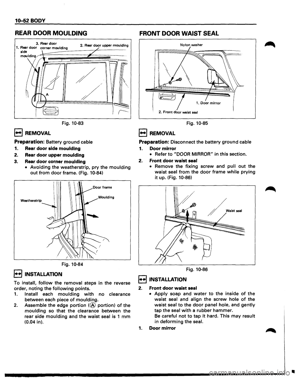
10-52 BODY
REAR DOOR MOULDING
2. Rear door upper moulding
1••1 REMOVAL
/
/
/
Fig. 10-83
Preparation: Battery ground cable
1. Rear door side moulding
2. Rear door upper moulding
3. Rear door corner moulding
/
• Avoiding the weatherstrip, pry the moulding
out from door frame. (Fig. 10-84)
Weatherstrip
Fig. 10-84
I••! INSTALLATION
To install, follow the removal steps in the reverse
order,
noting the following points.
1. Install each moulding with no clearance
between each piece of moulding.
2. Assemble the edge portion (@ portion) of the
moulding so that the clearance between the
rear side
moulding and the waist seal is 1 mm
(0.04 in).
FRONT DOOR WAIST SEAL
Nylon washer
2. Front door waist seal
Fig. 10-85
1••1 REMOVAL
Preparation: Disconnect the battery ground cable
1. Door mirror
• Refer to "DOOR MIRROR" in this section.
2. Front door waist seal
• Remove the fixing screw and pull out the
waist seal from the door frame while prying
it up. (Fig. 10-86)
Fig. 10-86
I••! INSTALLATION
2. Front door waist seal
~., ..... ,
• Apply soap and water to the inside of the
waist
seal and align the screw hole of the
waist seal to the door panel hole, and gently
tap the seal with a rubber hammer.
Be careful not to tap it hard. This may result
in deforming the seal.
1. Door mirror
•
Page 1840 of 1928
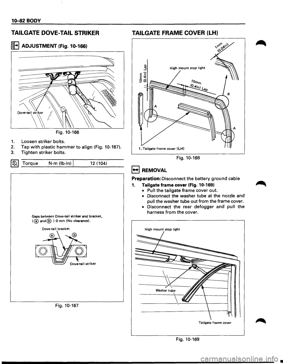
10-82 BODY
TAILGATE DOVE-TAIL STRIKER
I~FI ADJUSTMENT (Fig. 10-166)
Dove-tail striker 1/
\~!
Fig. 10-166
1. Loosen striker bolts.
2. Tap with plastic hammer to align (Fig. 10-167).
3. Tighten striker bolts.
~~~ Torque N·m (lb.in) I 12 (104)
Gaps between Dove-tail striker and bracket,
!@and@ ) 0 mm (No clearance).
Dove-tail bracket
Fig. 10-167
TAILGATE FRAME COVER (LH)
0. j High mount stop light
1. Tailgate frame cover (LH)
Fig. 10-168
1+•1 REMOVAL
Preparation:
Disconnect the battery ground cable
1. Tailgate frame cover (Fig. 10-169}
• Pull the tailgate frame cover out.
• Disconnect the washer tube at the nozzle and
pull the washer tube out from the frame cover.
• Disconnect the rear defogger and pull the
harness
from the cover.
High mount stop light
Tailgate frame cover
Fig. 10-169
•
Page 1883 of 1928
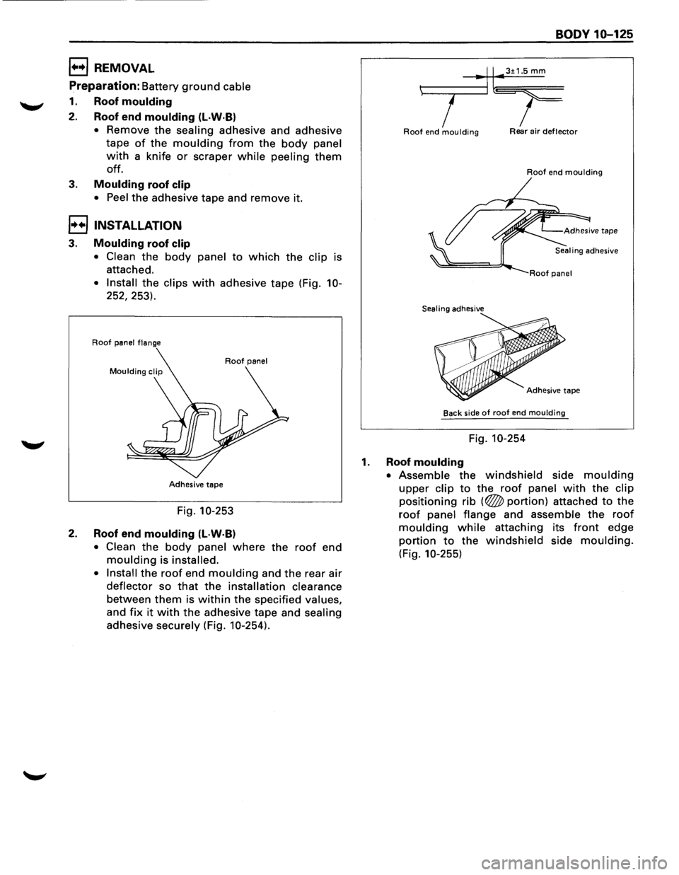
1••1 REMOVAL
Preparation: Battery ground cable
1. Roof moulding
2. Roof end moulding (L·W·B)
• Remove the sealing adhesive and adhesive
tape
of the moulding from the body panel
with a knife or scraper while peeling them
off.
3. Moulding roof clip
• Peel the adhesive tape and remove it.
I••! INSTALLATION
3. Moulding roof clip
• Clean the body panel to which the clip is
attached.
• Install the clips with adhesive tape (Fig. 10-
252, 253).
Roof panel flange
Roof panel
Adhesive tape
Fig. 10-253
2. Roof end moulding (l·W·B)
• Clean the body panel where the roof end
moulding is installed.
• Install
the roof end moulding and the rear air
deflector so that the installation clearance
between them is within the specified values,
and fix it with the adhesive tape and sealing
adhesive securely (Fig. 10-254).
BODY 10-125
t------.,.-lll•3±1.5 mm
7 I Roof end moulding Rear air deflector
Roof end moulding
Sealing adhesive
Adhesive
tape
Back side of roof end moulding
Fig. 10-254
1. Roof moulding
• Assemble the windshield side moulding
upper clip to the roof panel with the clip
positioning rib (~portion) attached to the
roof panel flange and assemble the roof
moulding while attaching its front edge
portion to the windshield side moulding.
(Fig. 10-255)