mirror controls ISUZU TROOPER 1995 Workshop Manual
[x] Cancel search | Manufacturer: ISUZU, Model Year: 1995, Model line: TROOPER, Model: ISUZU TROOPER 1995Pages: 1928
Page 1445 of 1928
-n ce· 0) I w 0 N
(
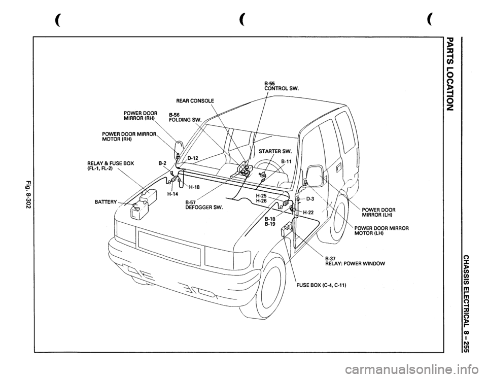
POWER
DOOR
MIRROR(RHI
""~
POWER
DOOR
MIRROR
MOTOR(RH)
RELAY
& FUSE
BOX
(FL-1,
FL-2)
~
"",
BATTERY~
(
REAR
CONSOLE
B-55 CONTROLSW.
B-37
POWER
DOOR
MIRROR
(LH)
". POWER
DOOR
MIRROR
MOTOR(LH)
RELAY:
POWER
WINDOW
(
~ ~ r-0 (') ~ -0 z
(") ::I: )> en
en iii m rm ~ :a n )> r-eo I N U'1 U'1
Page 1450 of 1928
8-260 CHASSIS ELECTRICAL
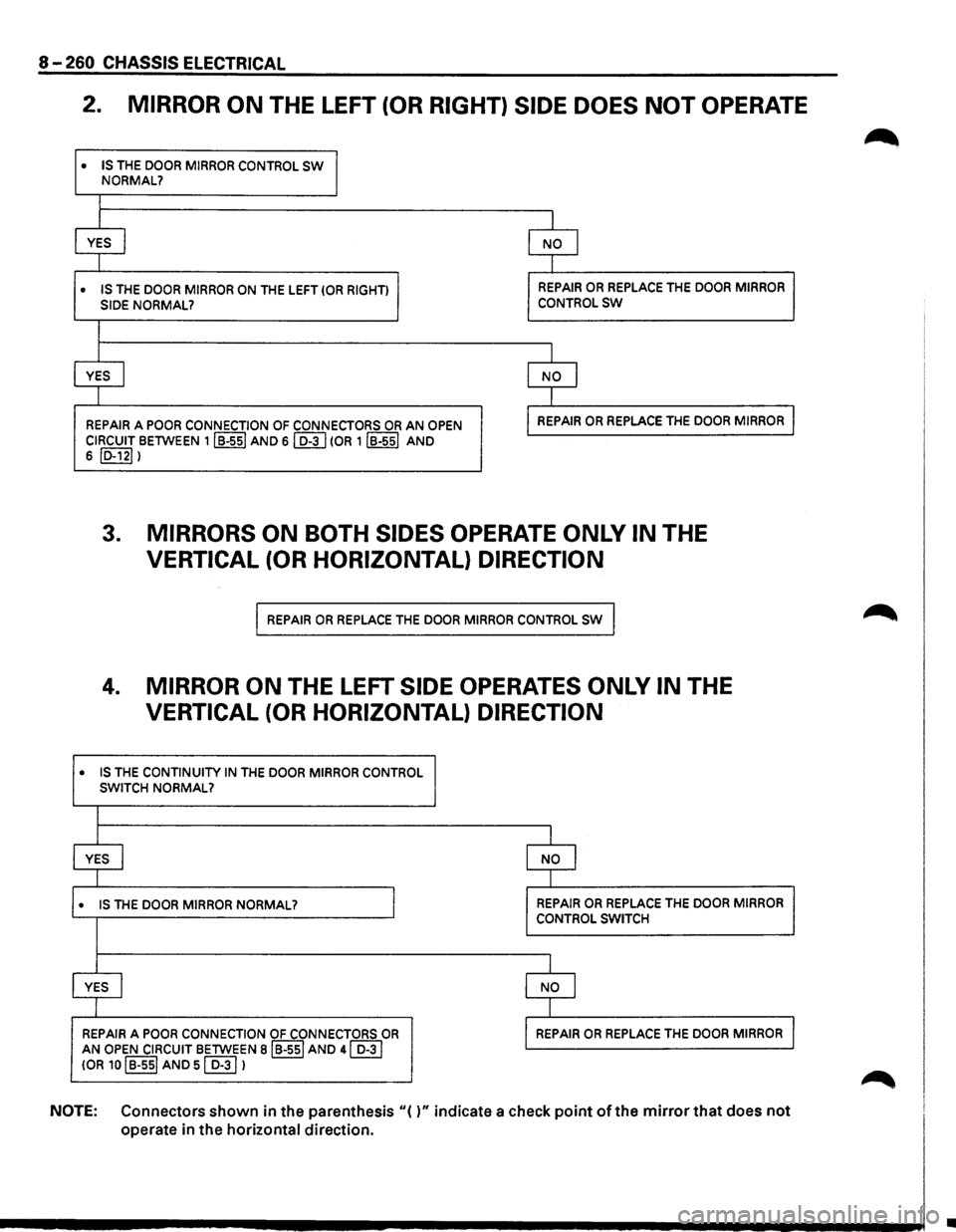
2. MIRROR ON THE LEFT (OR RIGHT) SIDE DOES NOT OPERATE
• IS THE DOOR MIRROR CONTROL SW
•
NORMAL?
I
I
I
YES I NO I
I I
IS THE DOOR MIRROR ON THE LEFT (OR RIGHT) REPAIR OR REPLACE THE DOOR MIRROR
SIDE NORMAL? CONTROLSW
I
I I
YES I NO I
1 I
REPAIR A POOR CONNECTION OF CONNECTORS OR AN OPEN REPAIR OR REPLACE THE DOOR MIRROR
CIRCUIT BETWEEN 1IB-ssl AND sl D-3 I (OR 1 IB-551 AND
6 ID-121 I
3. MIRRORS ON BOTH SIDES OPERATE ONLY IN THE
VERTICAL (OR HORIZONTAL) DIRECTION
REPAIR OR REPLACE THE DOOR MIRROR CONTROL SW
4. MIRROR ON THE LEFT SIDE OPERATES ONLY IN THE
VERTICAL (OR HORIZONTAL) DIRECTION
• IS THE CONTINUITY IN THE DOOR MIRROR CONTROL SWITCH NORMAL?
I
YES I NO I
I
• IS THE DOOR MIRROR NORMAL? I REPAIR OR REPLACE THE DOOR MIRROR
CONTROL SWITCH
I
YES I NO I
I
REPAIR A POOR CONNECTION OF CONNECTORS OR REPAIR OR REPLACE THE DOOR MIRROR
AN OPEN CIRCUIT BETWEEN BIB-551 AND 41 D-31
!OR 10 I B-ssl AND sl D-31 1
NOTE: Connectors shown in the parenthesis "( )" indicate a check point of the mirror that does not
operate in the horizontal direction.
•
Page 1454 of 1928
8-264 CHASSIS ELECTRICAL
STARTER SWITCH
Refer to "START AND CHARGING" in this section.
DOOR MIRROR SWITCH ASSEMBLY
(CONTROL SWITCH, FOLDING
SWITCH
AND DEFOGGER SWITCH)
(FIG. 8-305)
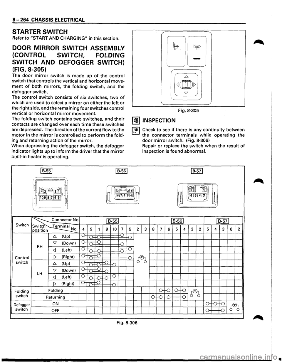
The door mirror switch is made up of the control
switch that controls the vertical and horizontal move
ment of both mirrors, the folding switch, and the
defogger switch.
The control switch consists of six switches, two of
which are used to select a mirror on either the left or
the right side, and the remaining four switches control
vertical or horizontal mirror movement.
The folding switch contains two switches, and their
contacts are changed over each time these switches
are depressed. The direction of the current flow to the
motor in the mirror is controlled to perform the fold
ing and returning action of the mirror.
When depressing the defogger switch, the defogger
indicator lights up to inform the driver that the mirror
built-in heater is operating.
I B-551 I B-561
i I I
!;l ~
LJ -J
I
I[~(@)~] J
Fig. 8-305
[!) INSPECTION
IL•I Check to see if there is any continuity between
the connector terminals while operating the
door mirror switch. (Fig. 8-306)
Repair or replace the switch when the result of
inspection is found abnormal.
I B-571
r .·~·· I ~ru·l
~~J!]}I ~ rroo~~l]
i !)~~1,1
a m
I ~ I ffi ;!sl7l6lsl41 ~ l~ lll"L•I'J'I•J ~~~
~' I J )
~0 ls-ssl IB-561 IB-571 Switch
N 4 9 1 8 10 7 5 2 3 8 7 6 5 4 3 2 5 4 3 6 2 o.
6. (Up) ~ ).. ...( ) .(")
'7 (Down) 0 c .) D RH c _.)
~ switch 6. (Up) c ~ -o ()-f-(l-
'7 (Down) 0 ( ) D LH c _.)
Folding Folding o-f-0 o--()
~ switch
Returning ()-Lo 0 0
Defogger ON o-'-0-
0
~ switch OFF 0 D
Fig. 8-306
•