brake pads replacement ISUZU TROOPER 1995 Workshop Manual
[x] Cancel search | Manufacturer: ISUZU, Model Year: 1995, Model line: TROOPER, Model: ISUZU TROOPER 1995Pages: 1928
Page 21 of 1928
FLUID LEVEL CHECK
A fluid loss in any system (except windshield
washer) may indicate a problem. Repair the system
at once.
Engine
oil level -Check level and add if
necessary. The best time to check the engine oil
level is
when the oil is warm. After stopping the
engine with the vehicle on a level surface, wait a
few minutes for the oil to drain back to the oil pan.
Pull
out the oil level indicator (dipstick). Wipe it
clean and push the oil level indicator back down all
the
way. Pull out the oil level indicator, keeping the
tip down, and look at the oil level on it.
Add oil, if needed, to keep the oil level above
the
"ADD" mark and between the "ADD" and
"FULL" marks in the operating range area. Avoid
overfilling the engine since this may cause engine
damage. Push
the oil level indicator back down all
the
way after taking the reading.
If you check the oil level when the oil is cold, do
not run the engine first. The cold oil will not drain
back
to the pan fast enough to give a true oil level.
Engine coolant level and condition -Check
engine coolant level in the coolant reservoir and
add engine
coolant if necessary. Inspect the engine
coolant and replace it if dirty or rusty.
Windshield washer fluid level -Check washer
fluid level in reservoir and add if necessary.
Power steering system reservoir level-Check
and keep at
proper level.
Brake master cylinder reservoir level -Check
fluid. Keep fluid at proper level. A low fluid level
can indicate
worn disc brake pads which may need
to be serviced.
Hydraulic clutch system -Check fluid l~vel in
the reservoir.
Add fluid as required.
Battery fluid level -Check fluid level in the
battery.
FLUID LEAK CHECK
Check for fuel, water, oil or other fluid leaks by
looking at the surface beneath the vehicle after it
has been parked for a while. Water dripping from
the air conditioning system after use is normal. If
you notice gasoline fumes or fluid at any time,
locate the source and correct it at once.
ENGINE OIL AND OIL FILTER
REPLACEMENT
Always use API SE, SF, SG, SH or ILSAC GF-1
quality oils of the proper viscosity.
When choosing an oil, consider the range of
temperatures the car will be operated in before the
next oil change. Then, select the recommended oil
viscosity
from the chart (Fig. OB-1).
Always change the oil and the oil filter as soon as
possible after driving in a dust storm.
MAINTENANCE AND LUBRICATION OB-5
ENGINE COOLING SYSTEM INSPECTION
Inspect coolant/anti-freeze. If coolant is dirty or
rusty, drain, flush and refill with new coolant. Keep
coolant at the proper mixture for proper freeze
protection,
corrosion inhibitor level and best engine
operating temperature.
Inspect hoses and replace if
cracked, swollen or deteriorated. Tighten hose
clamps if equipped with screw-type clamps. Clean
outside of radiator and air conditioning condenser.
Wash
filler cap and neck. To help ensure proper
operation, a pressure test of both the cooling
system and cap is also recommended.
EXHAUST SYSTEM INSPECTION
Visually inspect the exhaust pipes, muffler, heat
shields and hangers
for cracks, deterioration, or
damage.
Be alert to any changes in the sound of the exhaust
system
or any smell of fumes. These are signs the
system may be leaking or overheating. Repair the
system at once,
if these conditions exist. (See also
"Engine Exhaust Gas Safety" and "Three Way
Catalytic Converter" in Owner's manual.)
FUEL CAP, FUEL LINES, AND FUEL TANK
INSPECTION
Inspect the fuel tank, the fuel cap and the fuel lines
every
60,000 miles (96,000 km) for damage which
could cause leakage.
Inspect the fuel cap and the gasket for correct sealing
and physical damage. Replace any damaged parts.
DRIVE BELT INSPECTION
Check the belts driving the steering oil pump, the air
conditioning compressor, and the generator
for
cracks, fraying, wear, and correct tension every 30,000
miles (48,000 km). Adjust or replace as necessary.
WHEEL ALIGNMENT, BALANCE AND
TIRES OPERATION
Uneven or abnormal tire wear, or a pull right or left
on a straight and level road may show the need for
a wheel alignment. A vibration of the steering
wheel or seat at normal highway speeds means a
wheel balancing is needed. Check tire pressure
when the tires are "cold" (include the spare).
Maintain pressure as shown in the tire placard,
which is located on the driver's door lock pillar.
STEERING SYSTEM OPERATION
Be alert for any changes in steering action. An
inspection
or service is needed when the steering
wheel is harder
to turn or has too much free play, or
if there are unusual sounds when turning or parking.
Page 331 of 1928
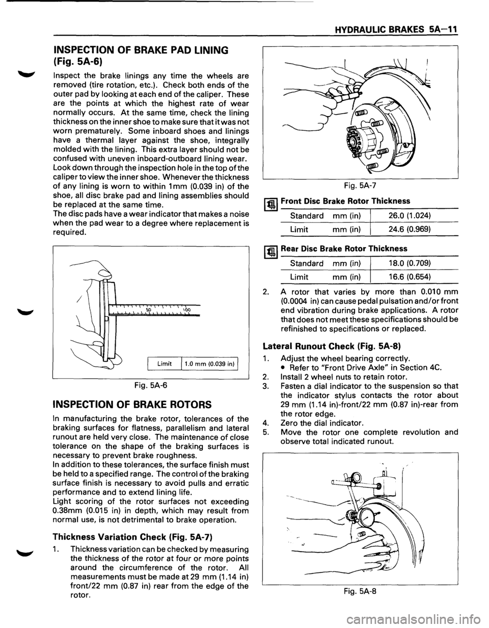
INSPECTION OF BRAKE PAD LINING
(Fig. SA-6)
Inspect the brake linings any time the wheels are
removed (tire rotation, etc.). Check both ends
of the
outer pad by
looking at each end of the caliper. These
are the points at which the highest rate
of wear
normally occurs. At the same time, check the lining
thickness on the inner shoe to make sure that it was not
worn prematurely. Some inboard shoes and linings
have a thermal layer against the shoe, integrally
molded
with the lining. This extra layer should not be
confused with uneven inboard-outboard lining wear.
Look
down through the inspection hole in the top of the
caliper to view the inner shoe. Whenever the thickness
of any lining is worn to within 1 mm (0.039 in) of the
shoe,
all disc brake pad and lining assemblies should
be replaced at the same time.
The disc pads have a
wear indicator that makes a noise
when the pad wear to a degree where replacement is
required.
100
Limit 11.0 mm (0.039 in) I
Fig. 5A-6
INSPECTION OF BRAKE ROTORS
In manufacturing the brake rotor, tolerances of the
braking surfaces
for flatness, parallelism and lateral
runout are held very close. The maintenance of close
tolerance
on the shape of the braking surfaces is
necessary to prevent brake roughness.
In addition to these tolerances, the surface finish must
be held to a specified range. The control ofthe braking
surface finish is necessary to avoid
pulls and erratic
performance and to extend
lining life.
Light scoring of the rotor surfaces not exceeding
0.38mm (0.015 in) in depth, which may result from
normal use, is not detrimental to brake operation.
Thickness Variation Check (Fig. 5A-7)
1. Thickness variation can be checked by measuring
the thickness
of the rotor at four or more points
around the circumference
of the rotor. All
measurements must be made at 29 mm (1.14 in)
front/22 mm (0.87 in) rear from the edge of the
rotor.
HYDRAULIC BRAKES 5A-11
Fig. 5A-7
~~~ Front Disc Brake Rotor Thickness
Standard mm (in) 26.0 (1.024)
Limit mm(in) 24.6 (0.969)
~~~Rear Disc Brake Rotor Thickness
Standard mm (in) 18.0 (0.709)
Limit mm (in) 16.6 (0.654)
2. A rotor that varies by more than 0.010 mm
(0.0004 in) can cause pedal pulsation and/or front
end vibration during brake applications. A rotor
that does not meet these specifications should be
refinished
to specifications or replaced.
Lateral Runout Check (Fig. 5A-8)
1. Adjust the wheel bearing correctly.
• Refer to "Front Drive Axle" in Section 4C.
2. Install 2 wheel nuts to retain rotor.
3. Fasten a dial indicator to the suspension so that
the indicator stylus contacts the rotor about
29 mm (1.14 in)-front/22 mm (0.87 in)-rear from
the rotor edge.
4. Zero the dial indicator.
5. Move the rotor one complete revolution and
observe
total indicated runout.
Fig. 5A-8
Page 351 of 1928
DISC BRAKES 5A2-1
SECTION 5A2
DISC BRAKES
w CAUTION:
All brake attaching fasteners are an important attaching part in that they could affect performance of vital
parts and systems, and/or could result in major repair expense. They must be replaced with one of the same
part
number or with an equivalent part if replacement becomes necessary. Do not use replacement parts of
lesser quality or substitute design. Torque values must be used as specified during reassembly to assure
proper retention of these parts.
CONTENTS
General Description . . . . . . . . . . . . . . . . . . . . 5A2-1
Operation . . . . . . . . . . . . . . . . . . . . . . . . . . . . 5A2-1
Diagnosis
..................... See Section SA
On-Vehicle Service . . . . . . . . . . . . . . . . . . . . 5A2-2
Front Disc Brakes . . . . . . . . . . . . . . . . . . . . 5A2-2
Brake Pads
Inspection . .
. . . . . . . . . . . . 5A2-2
Brake Pads Replacement . . . . . . . . . . . 5A2-3
Servicing
the Rotor . . . . . . . . . . . . . . . . 5A2-4
Caliper Replacement . .
. . . . . . . . . . . . . 5A2-6
Rebuilding
the Caliper . . . . . . . . . . . . . 5A2-8 Rear
Disc Brakes .................... 5A2-1 0
Brake
Pads Inspection ............. 5A2-1 0
Brake Pads Replacement ........... 5A2-1 0
Servicing the Rotor ............... 5A2-12
Caliper Replacement .............. 5A2-14
Rebuilding the
Caliper ............. 5A2-17
Parking Brakes . . . . . . . . . . . . . . . .
See Section SC
Main Data and Specifications ........... 5A2-19
General Specifications ............... 5A2-19
Torque Specifications
............... 5A2-19
GENERAL DESCRIPTION
The disc brake assembly consists of a caliper, piston,
rotor, pad assembly and
support bracket. The caliper
assembly has a single bore and is mounted to the
support bracket with 2 mounting bolts. The support
bracket allows the caliper to move laterally against the
rotor. The
caliper is a one-piece casting with the
inboard side containing the piston bore. A square cut
rubber
seal is located in a groove in the piston bore
which provides the hydraulic seal between the piston
and the cylinder
wall.
NOTE:
• Replace all components included in repair kits
used
to service this caliper.
• Lubricate rubber parts with clean brake fluid to
ease assembly.
• If any hydraulic component is removed or
disconnected, it may be necessary to bleed all or
part of the brake system.
• Replace pads in axle sets only.
•
The torque values specified are for dry,
unlubricated fasteners.
• Perform service operation a clean bench free
from all mineral oil materials.
OPERATION
Hydraulic pressure, created by applying the brake
pedal, is converted by the caliper to a stopping force.
This force acts
equally against the piston and the
bottom of the caliper bore to move the piston outward
and to move (slide) the caliper inward resulting in a
clamping action on the rotor. This clamping action
forces the
linings against the rotor, creating friction to
stop the vehicle.
Page 352 of 1928
5A2-2 DISC BRAKES
Front disc brakes
/
Rear disc brakes
I
I
Fig. 5A2-1
ON-VEHICLE SERVICE
FRONT DISC BRAKE
BRAKE PADS INSPECTION (Fig. 5A2-2)
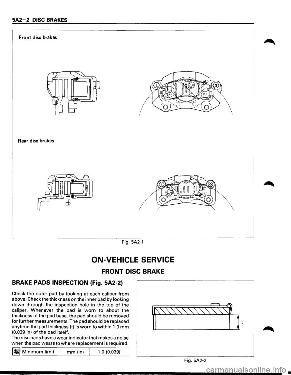
Check the outer pad by looking at each caliper from
above. Check the thickness on the inner pad by looking
down through the inspection hole in the top of the
caliper. Whenever the pad is worn to about the
thickness
of the pad base, the pad should be removed
for further measurements. The pad should be replaced
anytime the pad thickness (t) is worn to within 1.0 mm
(0.039 in) of the pad itself.
The disc pads have a wear indicator that makes a noise
when the pad wears
to where replacement is required.
~~~ Minimum limit mm (in) j 1.0 (0.039)
Fig. 5A2-2
I I
•
Page 353 of 1928
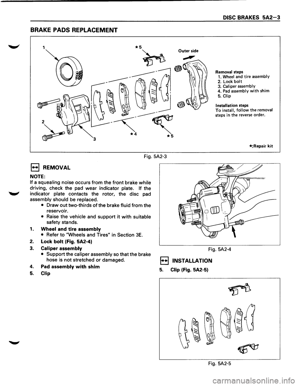
BRAKE PADS REPLACEMENT
1 Outer side
2
DISC BRAKES 5A2-3
Removal steps
1. Wheel and tire assembly
2. Lock
bolt 3. Caliper assembly
4. Pad assembly with shim
5. Clip
Installation
steps To install, follow the removal
steps in the reverse order.
*;Repair kit
Fig. 5A2-3
1••1 REMOVAL
NOTE:
If a squealing noise occurs from the front brake while
driving, check the pad wear indicator plate. If the
........., indicator plate contacts the rotor, the disc pad
assembly should be replaced.
•
Draw out two-thirds of the brake fluid from the
reservoir.
• Raise the vehicle and support it with suitable
safety stands.
1. Wheel and tire assembly
•
Refer to "Wheels and Tires" in Section 3E.
2. Lock bolt (Fig. 5A2-4)
3. Caliper assembly
• Support
the caliper assembly so that the brake
hose
is not stretched or damaged.
4. Pad assembly with shim
5. Clip
Fig. 5A2-4
1••1 INSTALLATION
5. Clip (Fig. 5A2-5)
Fig. 5A2-5
Page 358 of 1928
5A2-1 0 DISC BRAKES
REAR DISC BRAKE
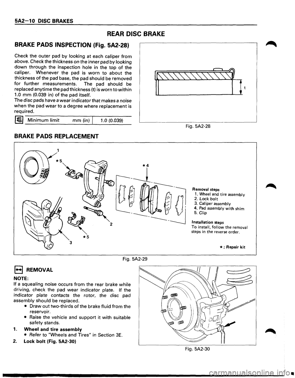
BRAKE PADS INSPECTION (Fig. 5A2-28)
Check the outer pad by looking at each caliper from
above. Check the thickness on the inner pad by looking
down through the inspection hole in the top of the
caliper. Whenever the pad is worn to about the
thickness
of the pad base, the pad should be removed
for further measurements. The pad should be
replaced anytime the pad thickness (t) is worn to within
1.0 mm (0.039 in) of the pad itself. 'f'-~1~
The disc pads have a wear indicator that makes a noise
when the pad wear to a degree where replacement is
required.
~~~-M--in-im __ u_m_l-im--it _____ m_m--(i-n)-rl--,-.-0-(0-.-03_9_) ___
BRAKE PADS REPLACEMENT
EJ REMOVAL
NOTE:
1
*5
3
Fig. 5A2-29
If a squealing noise occurs from the rear brake while
driving, check the pad wear indicator plate. If the
indicator
plate contacts the rotor, the disc pad
assembly should be replaced.
•
Draw out two-thirds of the brake fluid from the
reservoir.
• Raise the vehicle and support it with suitable
safety stands.
1. Wheel and tire assembly
•
Refer to "Wheels and Tires" in Section 3E.
2. Lock bolt (Fig. 5A2-30) Fig.
5A2-28
Removal steps
1. Wheel and tire assembly 2. Lock bolt 3. Caliper assembly
4. Pad assembly with shim 5. Clip
Installation
steps
To
install, follow the removal steps in the reverse order.
* ; Repair kit
Fig. 5A2-30
•