ISUZU TROOPER 1998 Service Repair Manual
Manufacturer: ISUZU, Model Year: 1998, Model line: TROOPER, Model: ISUZU TROOPER 1998Pages: 3573, PDF Size: 60.36 MB
Page 1821 of 3573
6A– 88 ENGINE MECHANICAL
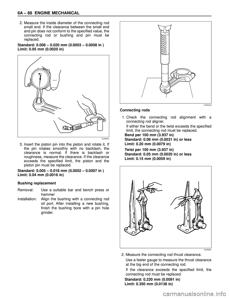
2. Measure the inside diameter of the connecting rod
small end. If the clearance between the small end
and pin does not conform to the specified value, the
connecting rod or bushing and pin must be
replaced.
Standard: 0.008 – 0.020 mm (0.0003 – 0.0008 in )
Limit: 0.05 mm (0.0020 in)
3. Insert the piston pin into the piston and rotate it. If
the pin rotates smoothly with no backlash, the
clearance is normal. If there is backlash or
roughness, measure the clearance. If the clearance
exceeds the specified limit, the piston and the
piston pin must be replaced.
Standard: 0.005 – 0.018 mm (0.0002 – 0.0007 in )
Limit: 0.04 mm (0.0016 in)
Bushing replacement
Removal: Use a suitable bar and bench press or
hammer
Installation: Align the bushing with a connecting rod
oil port. After installing a new bushing,
finish the bushing bore with a pin hole
grinder.Connecting rods
1. Check the connecting rod alignment with a
connecting rod aligner.
If either the bend or the twist exceeds the specified
limit, the connecting rod must be replaced.
Bend per 100 mm (3.937 in)
Standard: 0.08 mm (0.0031 in) or less
Limit: 0.20 mm (0.0079 in)
Twist per 100 mm (3.937 in)
Standard: 0.05 mm (0.0020 in) or less
Limit: 0.15 mm (0.0059 in)
2. Measure the connecting rod thrust clearance.
Use a feeler gauge to measure the thrust clearance
at the big end of the connecting rod.
If the clearance exceeds the specified limit, the
connecting rod must be replaced.
Standard: 0.230 mm (0.0091 in)
Limit: 0.350 mm (0.0138 in)
012RW074
012RW123
012RW001
Page 1822 of 3573
ENGINE MECHANICAL 6A– 89
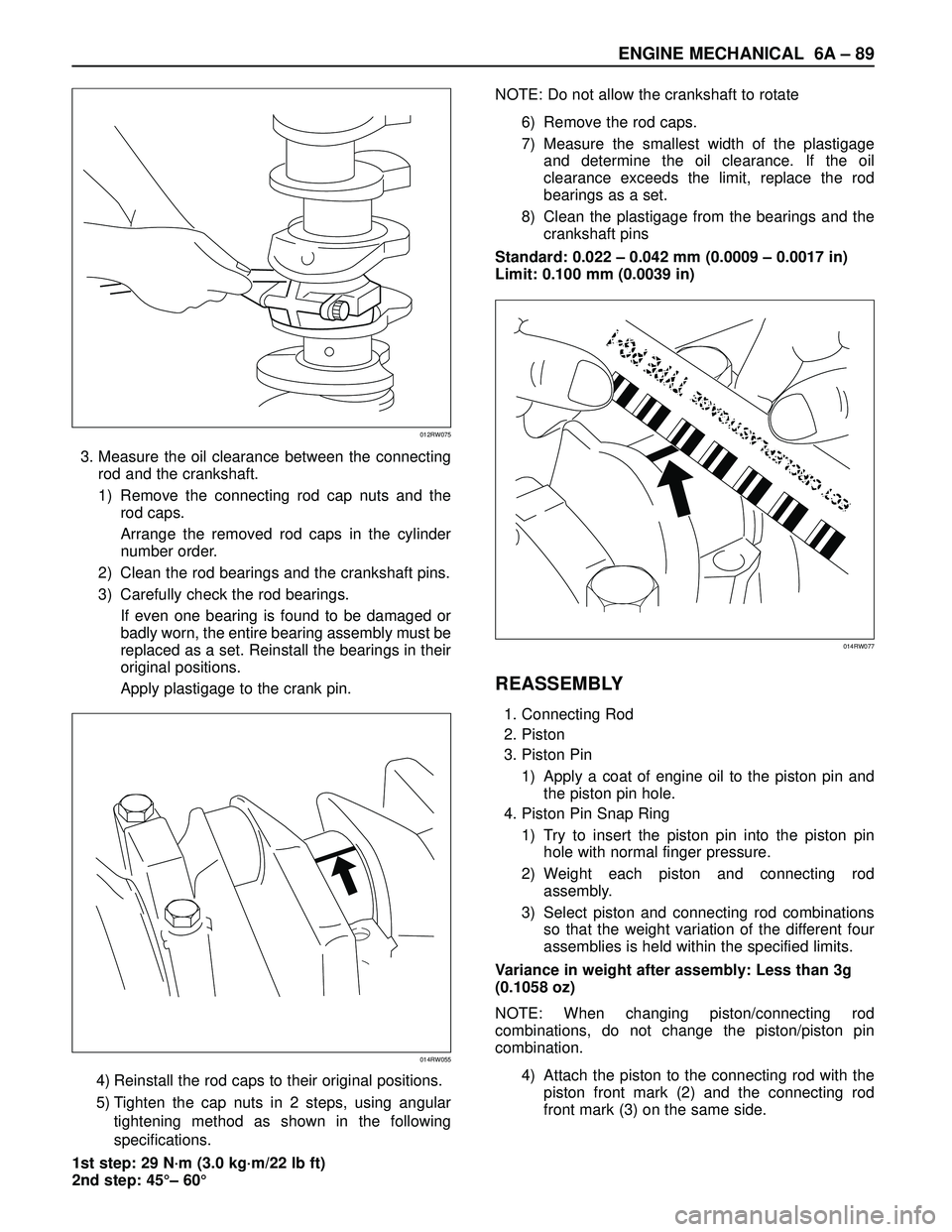
3. Measure the oil clearance between the connecting
rod and the crankshaft.
1) Remove the connecting rod cap nuts and the
rod caps.
Arrange the removed rod caps in the cylinder
number order.
2) Clean the rod bearings and the crankshaft pins.
3) Carefully check the rod bearings.
If even one bearing is found to be damaged or
badly worn, the entire bearing assembly must be
replaced as a set. Reinstall the bearings in their
original positions.
Apply plastigage to the crank pin.
4) Reinstall the rod caps to their original positions.
5) Tighten the cap nuts in 2 steps, using angular
tightening method as shown in the following
specifications.
1st step: 29 N·m (3.0 kg·m/22 lb ft)
2nd step: 45°– 60°NOTE: Do not allow the crankshaft to rotate
6) Remove the rod caps.
7) Measure the smallest width of the plastigage
and determine the oil clearance. If the oil
clearance exceeds the limit, replace the rod
bearings as a set.
8) Clean the plastigage from the bearings and the
crankshaft pins
Standard: 0.022 – 0.042 mm (0.0009 – 0.0017 in)
Limit: 0.100 mm (0.0039 in)
REASSEMBLY
1. Connecting Rod
2. Piston
3. Piston Pin
1) Apply a coat of engine oil to the piston pin and
the piston pin hole.
4. Piston Pin Snap Ring
1) Try to insert the piston pin into the piston pin
hole with normal finger pressure.
2) Weight each piston and connecting rod
assembly.
3) Select piston and connecting rod combinations
so that the weight variation of the different four
assemblies is held within the specified limits.
Variance in weight after assembly: Less than 3g
(0.1058 oz)
NOTE: When changing piston/connecting rod
combinations, do not change the piston/piston pin
combination.
4) Attach the piston to the connecting rod with the
piston front mark (2) and the connecting rod
front mark (3) on the same side.
014RW055
012RW075
014RW077
Page 1823 of 3573

6A– 90 ENGINE MECHANICAL
5. Piston Ring
1) Install the piston rings with the piston ring
expander.
The compression ring must be set with the 1N,
2N mark facing up.
2) Discerning mark is stamped as shown in the
illustration (1).
Marked 1N: 1st compression ring
Marked 2N: 2nd compression ring
3) Install piston rings in the following sequence.
1) Oil ring
(1) After installing the expander ring then assemble
the oil ring.
2) 2nd compression ring3) 1st compression ring
1) The compression ring must be set with the 1N or
2N mark facing up.
2) 1st compression ring:1N
3) 2nd compression ring: 2N
4) After installation, apply engine oil to the entire
circumference of the piston rings.
Check to see that all the rings rotate smoothly.
5) Insert the bearings into the connecting rods and
caps.
Apply new engine oil to the bearing faces.
Cap side bearings have no oil hole.
Connecting rod side bearing’s oil hole should be
aligned with oil hole on the connecting rod.
6. Piston and Connecting Rod
1) Apply engine oil to the cylinder bores, the
connecting rod bearings and the crankshaft
pins.
2) Check to see that the piston ring end gaps are
correctly positioned.
N
012RW037
2
3
1
015RW051
3
2
11
012RW058
Page 1824 of 3573

ENGINE MECHANICAL 6A– 91
Legend
(1) 1st compressor ring gap
(2) 2nd compressor ring gap
(3) Oil ring gap
3) Insert the piston/connecting rod assemblies into
each cylinder with the piston ring compressor.
4) The front marks must be facing the front of the
engine.
Piston Ring Compressor : 5-8840-9018-0
7. Connecting Rod Bearing Cap
1) Apply engine oil to thread and seat of bearing
cap bolts.
2) Tighten the cap bolts in 2 steps, using angular
tightening method as shown in the following
specifications.
1st step: 29 N·m (3.0 kg·m/22 lb ft)
2nd step: 45°– 60°
After tightening the cap bolts, check to see that
the crankshaft rotates smoothly.
8. Crank Case Assembly
1) Refer to “Crank Case” in this manual.
9. Cylinder Head Assembly
1) Refer to “Cylinder head” in this manual.
3
1
2
015RW083
Page 1825 of 3573
6A– 92 ENGINE MECHANICAL
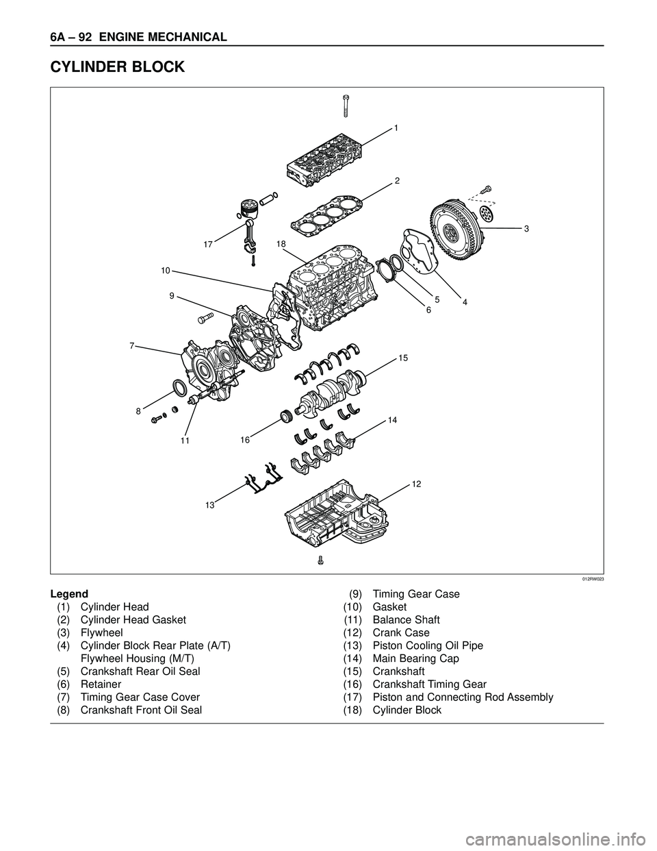
CYLINDER BLOCK
1
15
14
13
8
11
16
17
10
9
72
12
3
465
18
012RW023
Legend
(1) Cylinder Head
(2) Cylinder Head Gasket
(3) Flywheel
(4) Cylinder Block Rear Plate (A/T)
Flywheel Housing (M/T)
(5) Crankshaft Rear Oil Seal
(6) Retainer
(7) Timing Gear Case Cover
(8) Crankshaft Front Oil Seal(9) Timing Gear Case
(10) Gasket
(11) Balance Shaft
(12) Crank Case
(13) Piston Cooling Oil Pipe
(14) Main Bearing Cap
(15) Crankshaft
(16) Crankshaft Timing Gear
(17) Piston and Connecting Rod Assembly
(18) Cylinder Block
Page 1826 of 3573
ENGINE MECHANICAL 6A– 93
DISASSEMBLY
1. Cylinder Head Assembly
Refer to “Cylinder Head” in this manual.
2. Cylinder Head Gasket.
3. Flywheel
4. Cylinder Block Rear Plate (A/T), or Flywheel
housing (M/T).
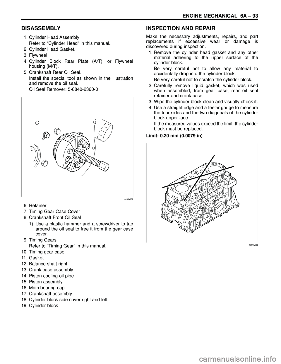
5. Crankshaft Rear Oil Seal.
Install the special tool as shown in the illustration
and remove the oil seal.
Oil Seal Remover: 5-8840-2360-0
6. Retainer
7. Timing Gear Case Cover
8. Crankshaft Front Oil Seal
1) Use a plastic hammer and a screwdriver to tap
around the oil seal to free it from the gear case
cover.
9. Timing Gears
Refer to “Timing Gear” in this manual.
10. Timing gear case
11. Gasket
12. Balance shaft right
13. Crank case assembly
14. Piston cooling oil pipe
15. Piston assembly
16. Main bearing cap
17. Crankshaft assembly
18. Cylinder block side cover right and left
19. Cylinder block
INSPECTION AND REPAIR
Make the necessary adjustments, repairs, and part
replacements if excessive wear or damage is
discovered during inspection.
1. Remove the cylinder head gasket and any other
material adhering to the upper surface of the
cylinder block.
Be very careful not to allow any material to
accidentally drop into the cylinder block.
Be very careful not to scratch the cylinder block.
2. Carefully remove liquid gasket, which was used
when assembled, from gear case, rear oil seal
retainer and crank case.
3. Wipe the cylinder block clean and visually check it.
4. Use a straight edge and a feeler gauge to measure
the four sides and the two diagonals of the cylinder
block upper face.
If the measured values exceed the limit, the cylinder
block must be replaced.
Limit: 0.20 mm (0.0079 in)
015RV002
012RW122
Page 1827 of 3573
6A– 94 ENGINE MECHANICAL
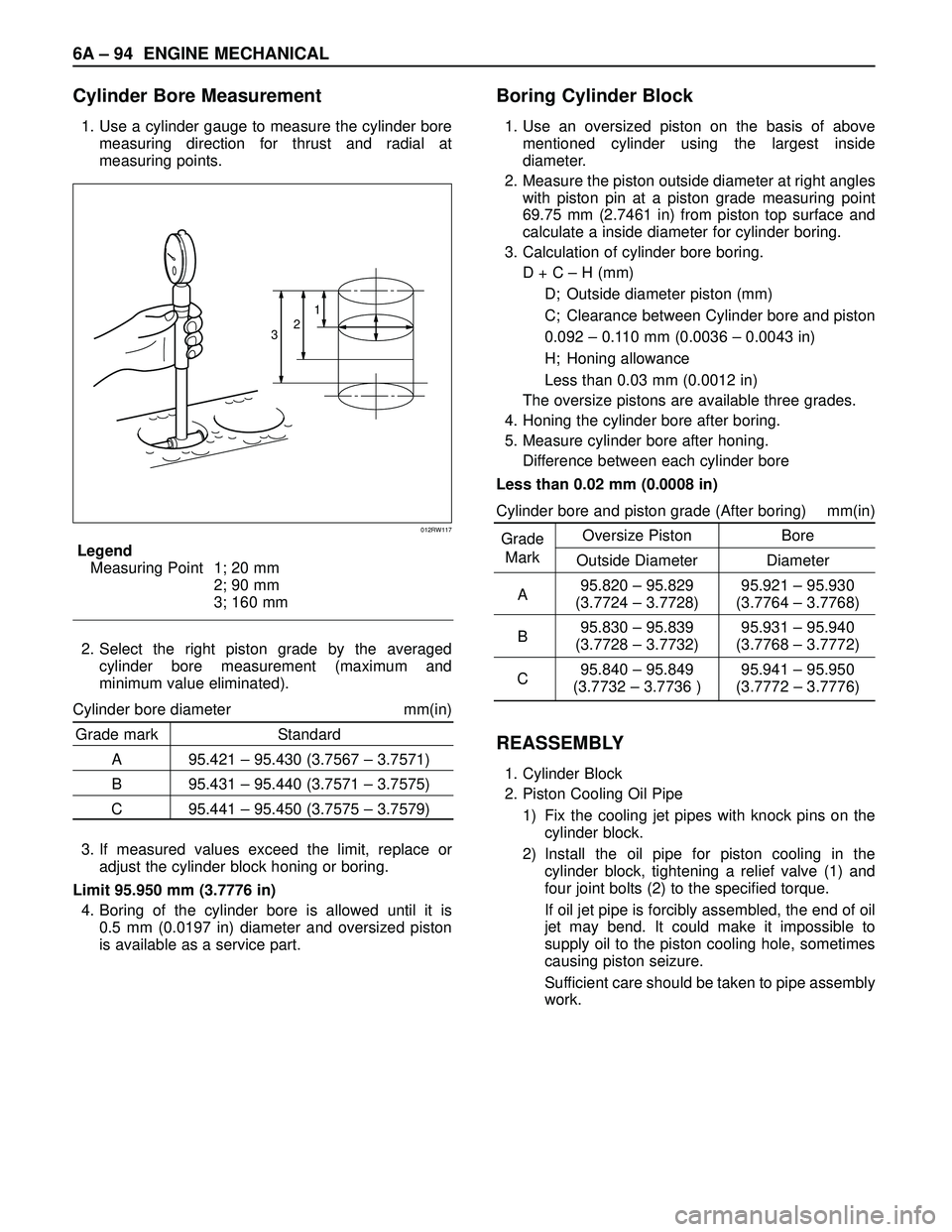
Cylinder Bore Measurement
1. Use a cylinder gauge to measure the cylinder bore
measuring direction for thrust and radial at
measuring points.
Legend
Measuring Point 1; 20 mm
2; 90 mm
3; 160 mm
2. Select the right piston grade by the averaged
cylinder bore measurement (maximum and
minimum value eliminated).
Cylinder bore diameter mm(in)
Grade mark Standard
A 95.421 – 95.430 (3.7567 – 3.7571)
B 95.431 – 95.440 (3.7571 – 3.7575)
C 95.441 – 95.450 (3.7575 – 3.7579)
3. If measured values exceed the limit, replace or
adjust the cylinder block honing or boring.
Limit 95.950 mm (3.7776 in)
4. Boring of the cylinder bore is allowed until it is
0.5 mm (0.0197 in) diameter and oversized piston
is available as a service part.
Boring Cylinder Block
1. Use an oversized piston on the basis of above
mentioned cylinder using the largest inside
diameter.
2. Measure the piston outside diameter at right angles
with piston pin at a piston grade measuring point
69.75 mm (2.7461 in) from piston top surface and
calculate a inside diameter for cylinder boring.
3. Calculation of cylinder bore boring.
D + C – H (mm)
D; Outside diameter piston (mm)
C; Clearance between Cylinder bore and piston
0.092 – 0.110 mm (0.0036 – 0.0043 in)
H; Honing allowance
Less than 0.03 mm (0.0012 in)
The oversize pistons are available three grades.
4. Honing the cylinder bore after boring.
5. Measure cylinder bore after honing.
Difference between each cylinder bore
Less than 0.02 mm (0.0008 in)
Cylinder bore and piston grade (After boring) mm(in)
GradeOversize Piston Bore
Mark
Outside Diameter Diameter
A95.820 – 95.829 95.921 – 95.930
(3.7724 – 3.7728) (3.7764 – 3.7768)
B95.830 – 95.839 95.931 – 95.940
(3.7728 – 3.7732) (3.7768 – 3.7772)
C95.840 – 95.849 95.941 – 95.950
(3.7732 – 3.7736 ) (3.7772 – 3.7776)
REASSEMBLY
1. Cylinder Block
2. Piston Cooling Oil Pipe
1) Fix the cooling jet pipes with knock pins on the
cylinder block.
2) Install the oil pipe for piston cooling in the
cylinder block, tightening a relief valve (1) and
four joint bolts (2) to the specified torque.
If oil jet pipe is forcibly assembled, the end of oil
jet may bend. It could make it impossible to
supply oil to the piston cooling hole, sometimes
causing piston seizure.
Sufficient care should be taken to pipe assembly
work.
321
012RW117
Page 1828 of 3573

ENGINE MECHANICAL 6A– 95
Oil pipe fixing bolts
M8: 20 N·m (2.0 kg·m/14 lb ft)
M6: 8 N·m (0.8 kg·m/69 lb in)
Relief valve fixing bolts : 30 N·m (3.1 kg·m/22 lb ft)
CAUTION: After installing the piston assembly,
check and see that there is appropriate clearance
between pistons and oil jet pipes by rotating
crankshaft slowly.
3. Crankshaft
1) Install the main bearings to the cylinder body
and the main bearing caps.
2) Be sure that they are positioned correctly.
3) Apply new engine oil to the upper and lower
main bearing faces.
4) Carefully mount the crankshaft.5) Apply engine oil to the thrust washer.
6) Assemble the thrust washer to the No. 3
bearing journal. The oil grooves must face the
crankshaft.
4. Main Bearing Cap Assembly
1) Install the bearing caps with the bearing cap
head arrow mark facing the front of the engine.
2) Apply engine oil to the crankshaft bearing cap
bolts.
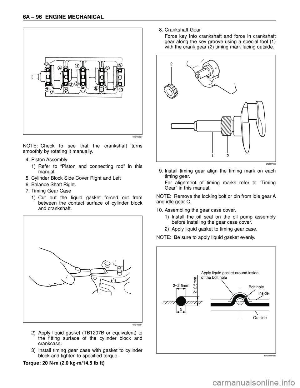
3) Tighten the crankshaft bearing cap bolts to the
specified torque a little at a time in the sequence
shown in the illustration.
Torque: 167 N·m (17.0 kg·m/123 lb ft)
321
012RW076
012RW038
012RW047
12345
012RW025
Page 1829 of 3573
6A– 96 ENGINE MECHANICAL
NOTE: Check to see that the crankshaft turns
smoothly by rotating it manually.
4. Piston Assembly
1) Refer to “Piston and connecting rod” in this
manual.
5. Cylinder Block Side Cover Right and Left
6. Balance Shaft Right.
7. Timing Gear Case
1) Cut out the liquid gasket forced out from
between the contact surface of cylinder block
and crankshaft.
2) Apply liquid gasket (TB1207B or equivalent) to
the fitting surface of the cylinder block and
crankcase.
3) Install timing gear case with gasket to cylinder
block and tighten to specified torque.
Torque: 20 N·m (2.0 kg·m/14.5 lb ft)8. Crankshaft Gear
Force key into crankshaft and force in crankshaft
gear along the key groove using a special tool (1)
with the crank gear (2) timing mark facing outside.
9. Install timing gear align the timing mark on each
timing gear.
For alignment of timing marks refer to “Timing
Gear” in this manual.
NOTE: Remove the locking bolt or pin from idle gear A
and idle gear C.
10. Assembling the gear case cover.
1) Install the oil seal on the oil pump assembly
before installing the gear case cover.
2) Apply liquid gasket to timing gear case.
NOTE: Be sure to apply liquid gasket evenly.
84159
610
23
7
012RW027
012RW064
12
2
012RW066
2
2~2.5mm
2~2.5mm
Apply liquid gasket around inside
of the bolt hole
Bolt hole
Inside
Outside
F06HX00001
Page 1830 of 3573
ENGINE MECHANICAL 6A– 97
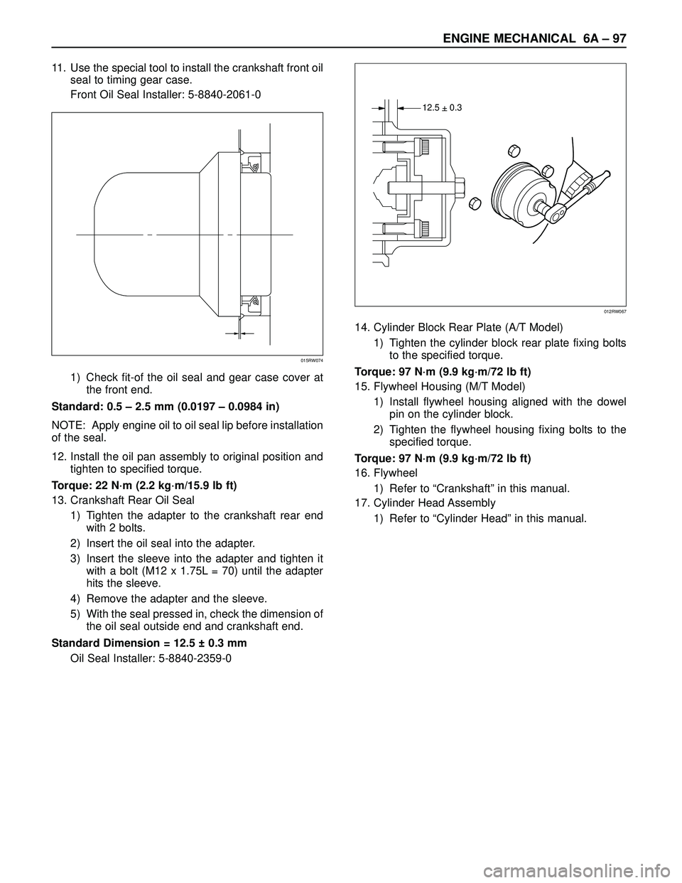
11. Use the special tool to install the crankshaft front oil
seal to timing gear case.
Front Oil Seal Installer: 5-8840-2061-0
1) Check fit-of the oil seal and gear case cover at
the front end.
Standard: 0.5 – 2.5 mm (0.0197 – 0.0984 in)
NOTE: Apply engine oil to oil seal lip before installation
of the seal.
12. Install the oil pan assembly to original position and
tighten to specified torque.
Torque: 22 N·m (2.2 kg·m/15.9 lb ft)
13. Crankshaft Rear Oil Seal
1) Tighten the adapter to the crankshaft rear end
with 2 bolts.
2) Insert the oil seal into the adapter.
3) Insert the sleeve into the adapter and tighten it
with a bolt (M12 x 1.75L = 70) until the adapter
hits the sleeve.
4) Remove the adapter and the sleeve.
5) With the seal pressed in, check the dimension of
the oil seal outside end and crankshaft end.
Standard Dimension = 12.5 ± 0.3 mm
Oil Seal Installer: 5-8840-2359-014. Cylinder Block Rear Plate (A/T Model)
1) Tighten the cylinder block rear plate fixing bolts
to the specified torque.
Torque: 97 N·m (9.9 kg·m/72 lb ft)
15. Flywheel Housing (M/T Model)
1) Install flywheel housing aligned with the dowel
pin on the cylinder block.
2) Tighten the flywheel housing fixing bolts to the
specified torque.
Torque: 97 N·m (9.9 kg·m/72 lb ft)
16. Flywheel
1) Refer to “Crankshaft” in this manual.
17. Cylinder Head Assembly
1) Refer to “Cylinder Head” in this manual.
015RW074
12.5 + 0.3–
012RW067