ISUZU TROOPER 1998 Service Repair Manual
TROOPER 1998
ISUZU
ISUZU
https://www.carmanualsonline.info/img/61/57184/w960_57184-0.png
ISUZU TROOPER 1998 Service Repair Manual
Page 2709 of 3573
8DÐ116 WIRING SYSTEM
Circuit Diagram (LHD)-2
DROPPING
RESISTOR
GLOW
PLUGGLOW
RELAY-2
QOS
III CONTROL UNITGLOW
RELAY-1
C-6612H-4216
1 1
C-60C-59 3.0
R/W
3.0
B/Y
3.0
B/R0.5
B/G0.5
B/G 0.85
B/Y FL-5 50A
GLOWC-531C-5921C-54 BATT.(+)
C-551
2C-55
AC-665H-417 3.0
B/R
0.5
B/L0.5
B/L 0.85
B/Y 0.85
B/Y
3.0
R/W
C-511C-51
C-521
2 2C-52
12
E-41
E-41
QOS THERMO SENSOR
(ENGINE) QOS III CONTROL UNIT
C-16 0.5
B 0.5
Y
0.5
Y0.5
B/Y
0.5
B
8C-66
10FENDER
-LH
C-66
8
C-66
4
H-48
H-412
D08RW981
Page 2710 of 3573
WIRING SYSTEM 8DÐ117
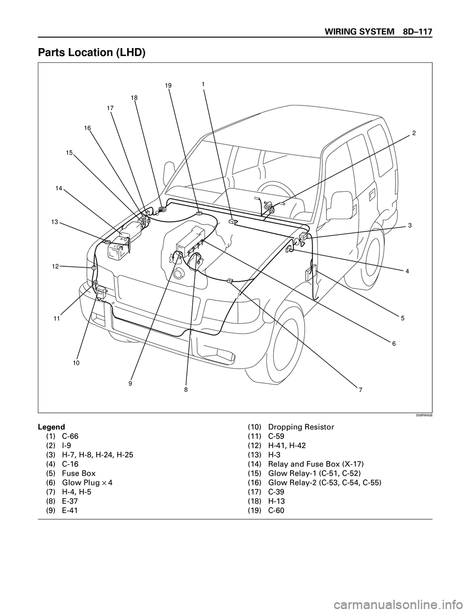
Parts Location (LHD)
Legend
(1) C-66
(2) I-9
(3) H-7, H-8, H-24, H-25
(4) C-16
(5) Fuse Box
(6) Glow Plug ´ 4
(7) H-4, H-5
(8) E-37
(9) E-41(10) Dropping Resistor
(11) C-59
(12) H-41, H-42
(13) H-3
(14) Relay and Fuse Box (X-17)
(15) Glow Relay-1 (C-51, C-52)
(16) Glow Relay-2 (C-53, C-54, C-55)
(17) C-39
(18) H-13
(19) C-60
1
2
3
4
5
6
7 8 9 10 11 12 13141516171819
D08RWA26
Page 2711 of 3573
8DÐ118 WIRING SYSTEM
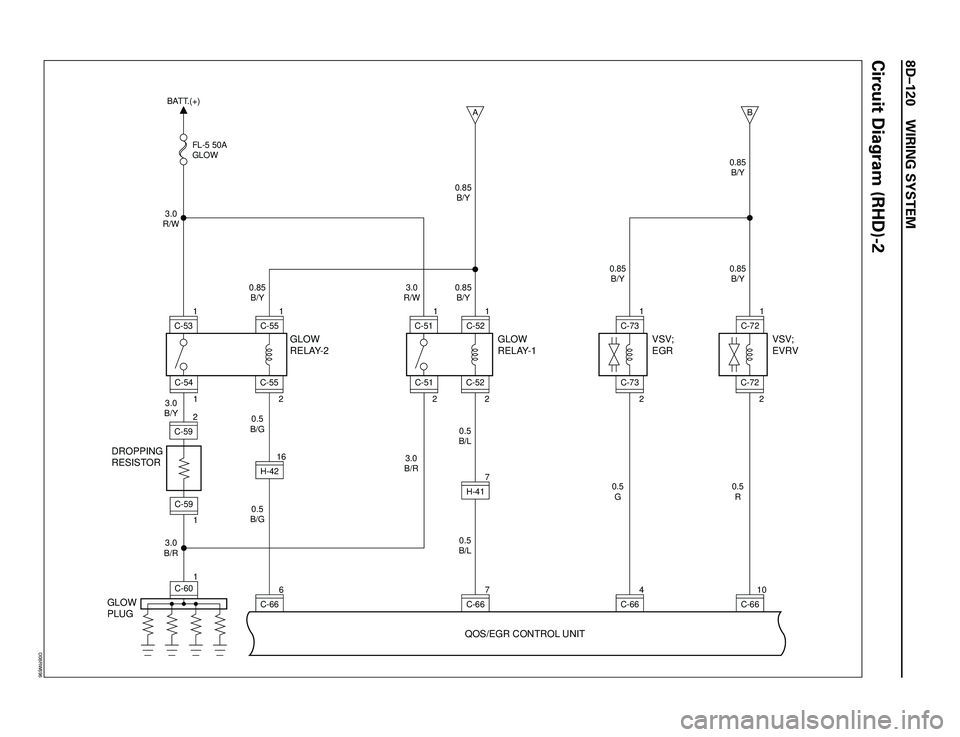
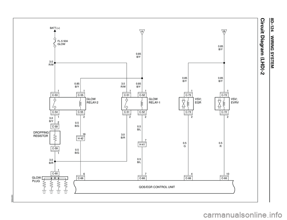
QOS and EGR System (4JG2)
General Description
The circuit consists of the starter switch, QOS/EGR
control unit, glow relay, charge relay, fuel cut
solenoid, dropping resistor, thermo sensor, glow
indicator light (meter), glow plug, vehicle speed
sensor, tacho sensor, throttle position sensor, EVRV
and VSV; EGR.
The engine coolant temperature at the time of the
engine start-up is sensed by the thermo sensor to
change the glow time so that the optimum starting
conditions can always be obtained.
The idling speed just after the engine start-up can
also be placed in the most suitable conditions in
accordance with the coolant temperature by the
operation of the delay timer.The indicator timer is activated upon the starter
switch turned to the ON position, and the indicator
light comes on for as much time as suitable for the
engine coolant temperature at the time of the
engine start-up.
EGR system controls the information of NOx by
returning a small amount of exhaust gas from the
intake manifold to the combustion chamber
through the EGR valve.
Page 2712 of 3573
WIRING SYSTEM 8DÐ119
Circuit Diagram (RHD)-1
0.5
B
0.5
W/G 0.85
W/G0.5
B0.5
B/Y
0.5
B/Y 0.85
B/Y0.5
L/Y
0.5
L/Y
0.5
P/W0.85
B/O 0.85
B/O 0.85
B/O
0.3
P/W 0.85
B/Y 0.85
B/Y 0.85
B/Y3.0
B/Y
C-8 15A
ENGINE
CHARGE
RELAY
GLOW
INDICATOR
LIGHT
(METER)
FUEL CUT
SOLENOID
AMBIENT
THERMO
SW QWS
THERMO SW
(ENGINE)
0.85
W/L
QOS/EGR CONTROL UNIT
C-6618
C-669
C-665
C-6617
C-6620
C-6616
C-391
X-172
I-915
H-4112
H-914
X-173
X-175H-33
1
X-17
26
I-9 4
X-17
FENDER-RHSTARTER SW
(IG1)AC GENERATOR
(L)
C-10 10A
METER, GAUGEC-9 15A
FUEL CUT
A 19
H-153.0
W/G
0.5
W/R0.5
BR
0.5
BR
0.5
BR
0.5
LG/Y
0.5
G/B
0.5
G/W 0.5
W/RC-1 10A
STARTER
RELAY STARTER SW
(ST)
4
H-71
E-40
11H-4
2C-743.0
L/R
0.5
BR
0.5
BR
0.5
BRC-20 10A
AIR CON HEATER & A/C
RELAY(4)
16
H-26
0.5
LG/W
0.3
LG/W VEHICLE SPEED
SENSOR(3)
15
H-5 12
H-76
H-26
H-57
H-412H-47E-402 7
E-371H-7
B
C
CH-167
C-74
1
D08RW695
Page 2713 of 3573
8DÐ120 WIRING SYSTEM
Circuit Diagram (RHD)-2
DROPPING
RESISTOR
GLOW
PLUGGLOW
RELAY-2
QOS/EGR CONTROL UNITGLOW
RELAY-1
C-666H-4216
1 1
C-60C-59 3.0
R/W
3.0
B/Y
3.0
B/R0.5
B/G0.5
B/G 0.85
B/Y FL-5 50A
GLOWC-531C-5921C-54 BATT.(+)
C-551
2C-55
AC-667H-417 3.0
B/R
0.5
B/L0.5
B/L 0.85
B/Y 0.85
B/Y
3.0
R/W
C-511C-51
C-521
2 2C-52
VSV;
EVRV
BC-6610 0.5
R 0.85
B/Y 0.85
B/YC-721
2C-72
VSV;
EGR
C-664 0.5
G 0.85
B/YC-731
2C-73
D08RW696
Page 2715 of 3573
8DÐ122 WIRING SYSTEM
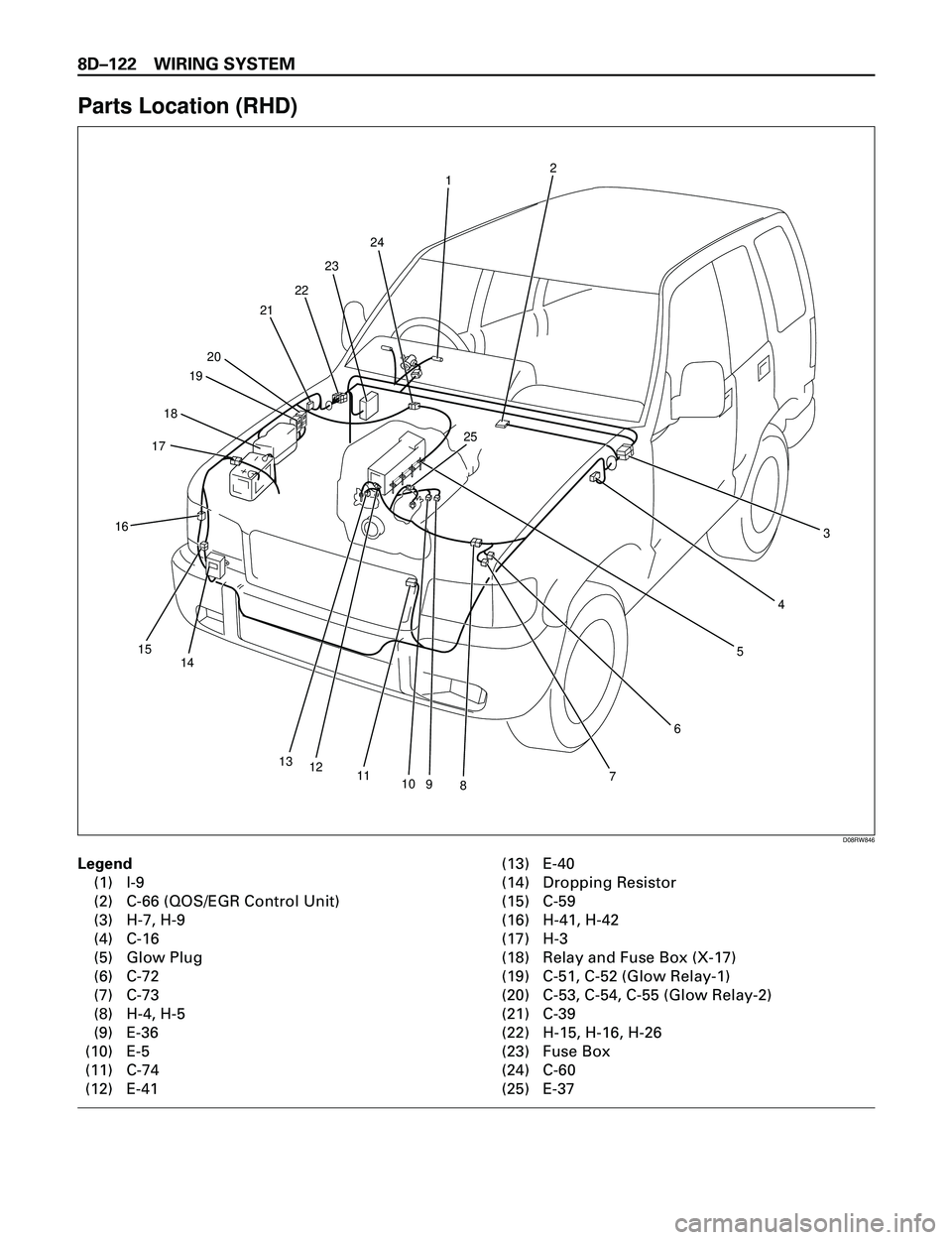
Parts Location (RHD)
Legend
(1) I-9
(2) C-66 (QOS/EGR Control Unit)
(3) H-7, H-9
(4) C-16
(5) Glow Plug
(6) C-72
(7) C-73
(8) H-4, H-5
(9) E-36
(10) E-5
(11) C-74
(12) E-41(13) E-40
(14) Dropping Resistor
(15) C-59
(16) H-41, H-42
(17) H-3
(18) Relay and Fuse Box (X-17)
(19) C-51, C-52 (Glow Relay-1)
(20) C-53, C-54, C-55 (Glow Relay-2)
(21) C-39
(22) H-15, H-16, H-26
(23) Fuse Box
(24) C-60
(25) E-37
1
3
4
6
78910
12 13 14 15 161718192021
22
25 23
24
115
2
D08RW846
Page 2716 of 3573
WIRING SYSTEM 8DÐ123
0.5
B
0.5
W/G 0.85
W/G0.5
B0.5
B/Y
0.5
B/Y 0.85
B/Y0.5
L/Y
0.5
L/Y
0.5
P/W0.85
B/O 0.85
B/O 0.85
B/O
0.3
P/W 0.85
B/Y 0.85
B/Y 0.85
B/Y3.0
B/Y
C-8 15A
ENGINE
CHARGE
RELAY
GLOW
INDICATOR
LIGHT
(METER)
FUEL CUT
SOLENOID
AMBIENT
THERMO
SW QWS
THERMO SW
(ENGINE)
0.85
W/L
QOS/EGR CONTROL UNIT
C-6618
C-669
C-665
C-6617
C-6620
C-6616
C-392
X-172
I-915
H-4112
H-241
X-173
X-175H-33
1
X-17
26
I-9 4
X-17
FENDER-RHSTARTER SW
(IG1)AC GENERATOR
(L)
C-10 10A
METER, GAUGEC-9 15A
FUEL CUT
A 3
H-133.0
W/G
0.5
W/R0.5
BR
0.5
BR
0.5
BR
0.5
LG/Y
0.5
G/B
0.5
G/W 0.5
W/RC-1 10A
STARTER
RELAY STARTER SW
(ST)
6
H-81
E-40
11H-4
2C-743.0
L/R
0.5
BR
0.5
BR
0.5
BRC-20 10A
AIR CON HEATER & A/C
RELAY(4)
14
H-26
0.5
LG/W
0.3
LG/W VEHICLE SPEED
SENSOR(3)
15
H-5 13
H-810
H-25
H-57
H-412H-47E-402 7
E-371H-8
B
C
CH-1617
C-74
1
D08RW984
Circuit Diagram (LHD)-1
Page 2717 of 3573
8DÐ124 WIRING SYSTEM
DROPPING
RESISTOR
GLOW
PLUGGLOW
RELAY-2
QOS/EGR CONTROL UNITGLOW
RELAY-1
C-666H-4216
1 1
C-60C-59 3.0
R/W
3.0
B/Y
3.0
B/R0.5
B/G0.5
B/G 0.85
B/Y FL-5 50A
GLOWC-531C-5921C-54 BATT.(+)
C-551
2C-55
AC-667H-417 3.0
B/R
0.5
B/L0.5
B/L 0.85
B/Y 0.85
B/Y
3.0
R/W
C-511C-51
C-521
2 2C-52
VSV;
EVRV
BC-6610 0.5
R 0.85
B/Y 0.85
B/YC-721
2C-72
VSV;
EGR
C-664 0.5
G 0.85
B/YC-731
2C-73
D08RW985
Circuit Diagram (LHD)-2
Page 2719 of 3573
8DÐ126 WIRING SYSTEM
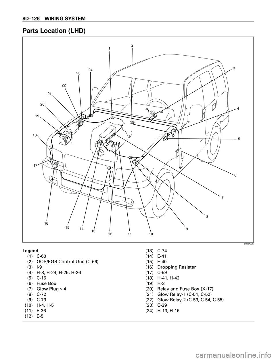
Parts Location (LHD)
Legend
(1) C-60
(2) QOS/EGR Control Unit (C-66)
(3) I-9
(4) H-8, H-24, H-25, H-26
(5) C-16
(6) Fuse Box
(7) Glow Plug ´ 4
(8) C-72
(9) C-73
(10) H-4, H-5
(11) E-36
(12) E-5(13) C-74
(14) E-41
(15) E-40
(16) Dropping Resister
(17) C-59
(18) H-41, H-42
(19) H-3
(20) Relay and Fuse Box (X-17)
(21) Glow Relay-1 (C-51, C-52)
(22) Glow Relay-2 (C-53, C-54, C-55)
(23) C-39
(24) H-13, H-16
12
3
4
5
6
7
8
9
10 11 12 13 14 15 16 17 18192021222324
D08RWA25
Page 2720 of 3573
WIRING SYSTEM 8DÐ127
Headlight and Fog Light
General Description
The circuit consists of the headlight, FRT fog light,
lighting SW, dimmerápassing SW, FRT fog light SW,
high beam indicator, tail relay, lighting relay, FRT
fog light relay and dimmer relay (LHD).
When the lighting SW is turned on by setting it at
headlight position, the lighting relay is activated to
turn on the headlight. The optical axis of the
headlight can be turned up or down by operating the
dimmer SW while the headlight is on.
The passing SW is independent of the lighting SW,
and the optical axis of the passing light can beturned up only while the switch lever is pulled up
and held in this state.
FRT fog lights turn on when the lighting SW is at
clearance light or headlight position.

