ISUZU TROOPER 1998 Service Repair Manual
Manufacturer: ISUZU, Model Year: 1998, Model line: TROOPER, Model: ISUZU TROOPER 1998Pages: 3573, PDF Size: 60.36 MB
Page 2851 of 3573
8DÐ258 WIRING SYSTEM
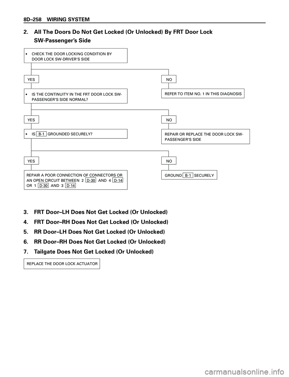
2. All The Doors Do Not Get Locked (Or Unlocked) By FRT Door Lock
SW-PassengerÕs Side
YES
·CHECK THE DOOR LOCKING CONDITION BY
DOOR LOCK SW-DRIVER'S SIDE
·IS THE CONTINUITY IN THE FRT DOOR LOCK SW-
PASSENGER'S SIDE NORMAL?
NO
REFER TO ITEM NO. 1 IN THIS DIAGNOSIS
YES
·IS B-1 GROUNDED SECURELY?
NO
REPAIR OR REPLACE THE DOOR LOCK SW-
PASSENGER'S SIDE
YES
REPAIR A POOR CONNECTION OF CONNECTORS OR
AN OPEN CIRCUIT BETWEEN 2 D-30 AND 4 D-14
OR 1 D-30 AND 3 D-14
NO
GROUND B-1 SECURELY
3. FRT DoorÐLH Does Not Get Locked (Or Unlocked)
4. FRT DoorÐRH Does Not Get Locked (Or Unlocked)
5. RR DoorÐLH Does Not Get Locked (Or Unlocked)
6. RR DoorÐRH Does Not Get Locked (Or Unlocked)
7. Tailgate Does Not Get Locked (Or Unlocked)
REPLACE THE DOOR LOCK ACTUATOR
Page 2852 of 3573
WIRING SYSTEM 8DÐ259
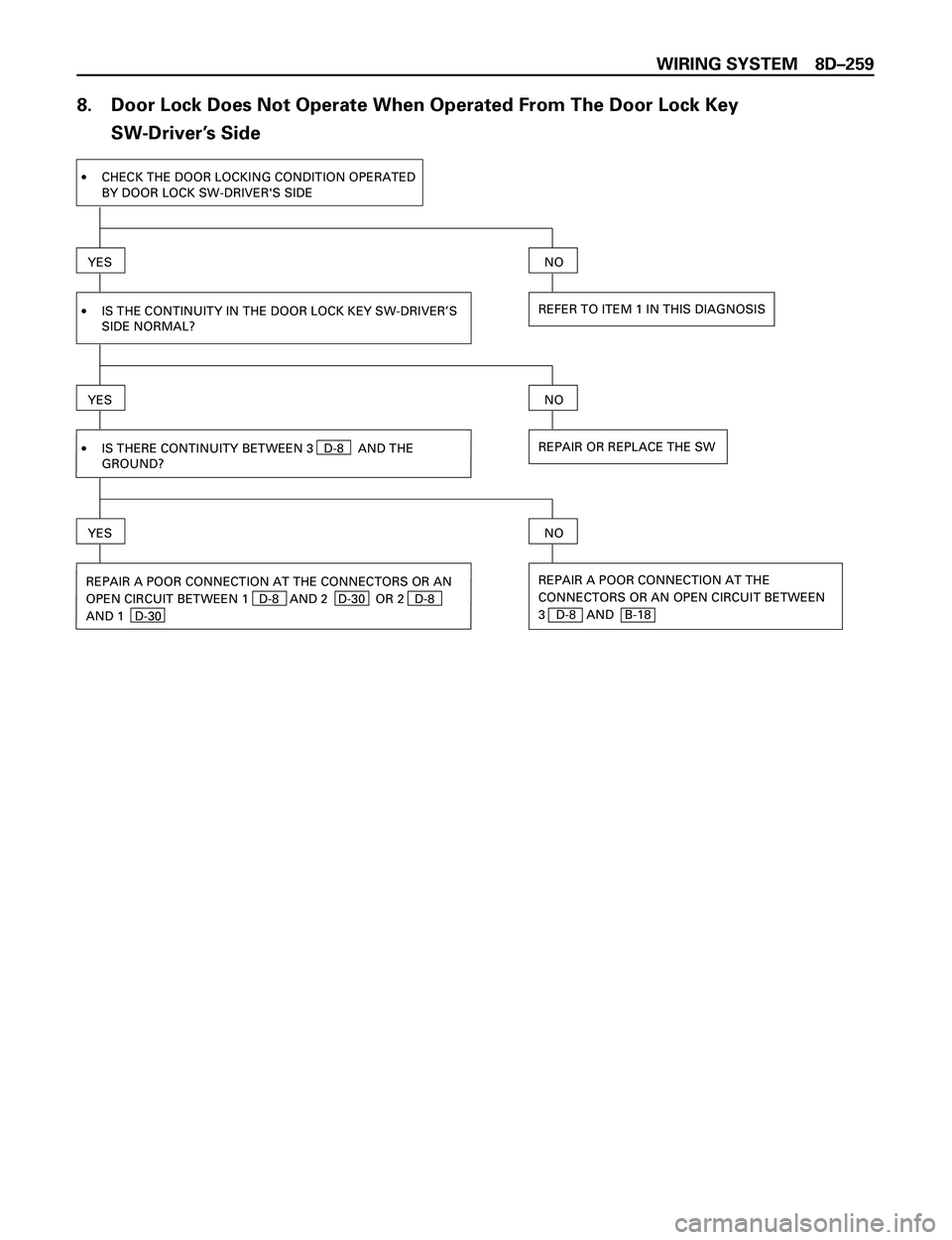
8. Door Lock Does Not Operate When Operated From The Door Lock Key
SW-DriverÕs Side
YES
·IS THE CONTINUITY IN THE DOOR LOCK KEY SW-DRIVER’S
SIDE NORMAL?
YES
REFER TO ITEM 1 IN THIS DIAGNOSIS
NO
·CHECK THE DOOR LOCKING CONDITION OPERATED
BY DOOR LOCK SW-DRIVER'S SIDE
REPAIR OR REPLACE THE SW
NO
·IS THERE CONTINUITY BETWEEN 3 D-8 AND THE
GROUND?
YES
REPAIR A POOR CONNECTION AT THE
CONNECTORS OR AN OPEN CIRCUIT BETWEEN
3 D-8 AND B-18
NO
REPAIR A POOR CONNECTION AT THE CONNECTORS OR AN
OPEN CIRCUIT BETWEEN 1 D-8 AND 2 D-30 OR 2 D-8
AND 1 D-30
Page 2853 of 3573
8DÐ260 WIRING SYSTEM
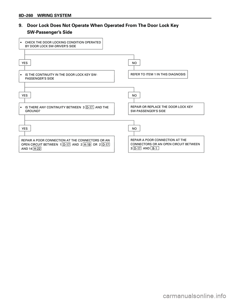
9. Door Lock Does Not Operate When Operated From The Door Lock Key
SW-PassengerÕs Side
YES
·IS THE CONTINUITY IN THE DOOR LOCK KEY SW-
PASSENGER’S SIDE
YES
REFER TO ITEM 1 IN THIS DIAGNOSIS
NO
·CHECK THE DOOR LOCKING CONDITION OPERATED
BY DOOR LOCK SW-DRIVER’S SIDE
REPAIR OR REPLACE THE DOOR LOCK KEY
SW-PASSENGER’S SIDE
NO
·IS THERE ANY CONTINUITY BETWEEN 3 D-17 AND THE
GROUND?
YES
REPAIR A POOR CONNECTION AT THE
CONNECTORS OR AN OPEN CIRCUIT BETWEEN
3 D-17 AND B-1
NO
REPAIR A POOR CONNECTION AT THE CONNECTORS OR AN
OPEN CIRCUIT BETWEEN 1 D-17 AND 2 H-19 OR 2 D-17
AND 14 H-22
Page 2854 of 3573
WIRING SYSTEM 8DÐ261
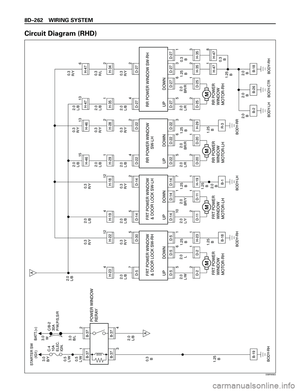
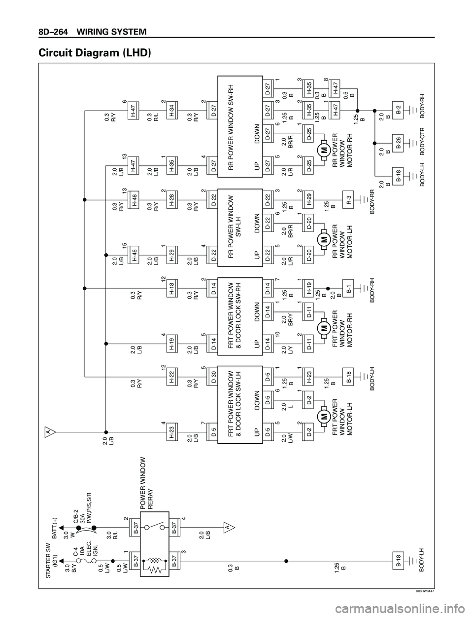
Power Window
General Description
The circuit consists of (door lock &) power window
switch for each of front windows, power window
switch for rear doors and power window motors.
When starter switch is turned on, battery voltage is
applied to each of power window switches through
circuit breaker and power window relay on the
circuit.
DriverÕs power window switch has ÒONE TOUCHÓ
function for driverÕs side window.
This function opens driverÕs side window fully by
just setting the switch to ÒAUTOÓ position.
When lock switch on driverÕs side power window
switch is depressed, battery voltage to passengerÕs
power window switches are shut off. So, even if
these switches are operated, power window motor
does not operate.
Page 2855 of 3573
8DÐ262 WIRING SYSTEM
Circuit Diagram (RHD)
B-371
B-372
B-37
3
B-37
4A
A
B-19
H-234D-570.3
R/Y0.3
R/Y2.0
L/B
1.25
B
1.25
B
BODY-RH
BODY-RH2.0
L/B 2.0
L/B
2.0
L/W
1.25
B 0.3
B 0.5
L/W0.5
L/W3.0
B/Y STARTER SW
(IG1)BATT.(+)
C-4
10A
ELEC.
IGN.C/B-2
30A
P/W,P/S,S/R
2.0
L/B3.0
B/L3.0
W
POWER WINDOW
RERAY
2.0
L
FRT POWER
WINDOW
MOTOR-RH
D-305
D-5
56D-5
D-5
UP DOWN FRT POWER WINDOW
& DOOR LOCK SW-RH
1
D-221
H-23
D-21
B-18
M
H-194D-145
H-1812
0.3
R/Y0.3
R/Y
1.25
B
1.25
B
2.0
B
BODY-LH 2.0
L/B
2.0
L/Y2.0
BR/Y
FRT POWER
WINDOW
MOTOR-LH
D-142
D-14
10 1D-14
D-14
UP DOWN FRT POWER WINDOW
& DOOR LOCK SW-LH
7
D-1121
H-19
D-111
B-1
M
2.0
L/B2.0
L/BH-291H-4615
H-4613
D-224
H-282
0.3
R/Y0.3
R/Y0.3
R/Y
1.25
B
1.25
B
BODY-RR 2.0
L/B
2.0
L/R2.0
BR/R
RR POWER
WINDOW
MOTOR-LH
D-222
D-22
56D-22
D-22
UP DOWNRR POWER WINDOW
SW-LH
3
D-2021
H-29
D-202
R-3
M
2.0
L/B2.0
L/BH-351H-4713
H-476
D-274
H-342
0.3
R/Y0.3
R/L0.3
R/Y
1.25
B0.3
B
0.3
B
2.0
B 2.0
B 2.0
B1.25
B
BODY-RH 2.0
L/B
2.0
L/R2.0
BR/R
RR POWER
WINDOW
MOTOR-RH
D-272
D-27
56D-27
D-27
UP DOWN RR POWER WINDOW SW-RH
3
D-2521
H-35
D-252
H-47B-18
BODY-CTRB-26
BODY-LHB-21
D-27
1H-353H-478
M
H-2212
D08RW663
Page 2856 of 3573
WIRING SYSTEM 8DÐ263
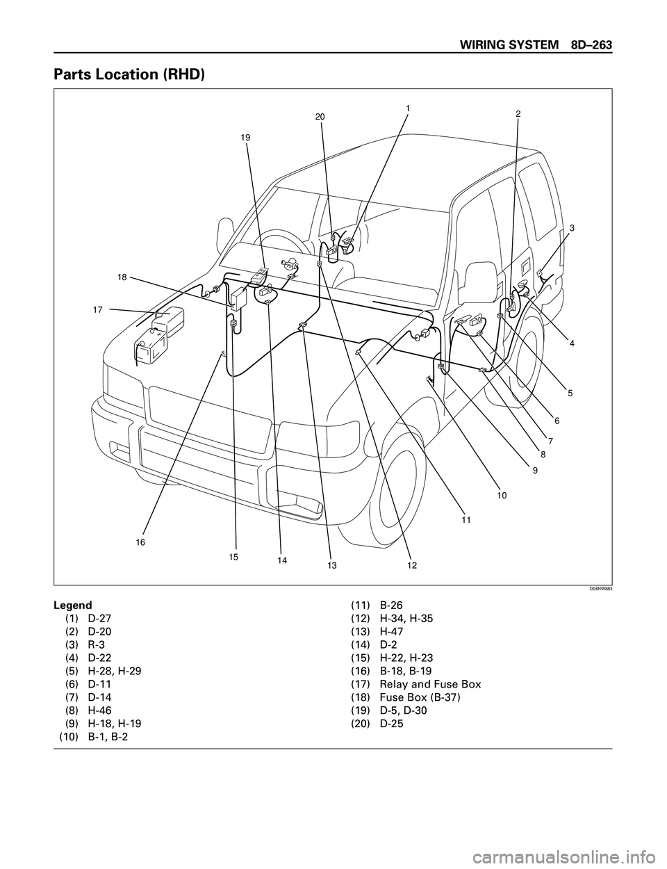
Parts Location (RHD)
Legend
(1) D-27
(2) D-20
(3) R-3
(4) D-22
(5) H-28, H-29
(6) D-11
(7) D-14
(8) H-46
(9) H-18, H-19
(10) B-1, B-2(11) B-26
(12) H-34, H-35
(13) H-47
(14) D-2
(15) H-22, H-23
(16) B-18, B-19
(17) Relay and Fuse Box
(18) Fuse Box (B-37)
(19) D-5, D-30
(20) D-25
19
9 2
4
18
17
3
201
10
11
121314 15
16
5
6
7
8
D08RW883
Page 2857 of 3573
8DÐ264 WIRING SYSTEM
Circuit Diagram (LHD)
B-371
B-372
B-37
3
B-37
4A
A
B-18
H-234D-570.3
R/Y0.3
R/Y2.0
L/B
1.25
B
1.25
B
BODY-LH
BODY-LH2.0
L/B 2.0
L/B
2.0
L/W
1.25
B 0.3
B 0.5
L/W0.5
L/W3.0
B/Y STARTER SW
(IG1)BATT.(+)
C-4
10A
ELEC.
IGN.C/B-2
30A
P/W,P/S,S/R
2.0
L/B3.0
B/L3.0
W
POWER WINDOW
RERAY
2.0
L
FRT POWER
WINDOW
MOTOR-LH
D-305
D-5
56D-5
D-5
UP DOWN FRT POWER WINDOW
& DOOR LOCK SW-LH
1
D-221
H-23
D-21
B-18
M
H-194D-145
H-1812
0.3
R/Y0.3
R/Y
1.25
B
1.25
B
2.0
B
BODY-RH 2.0
L/B
2.0
L/Y2.0
BR/Y
FRT POWER
WINDOW
MOTOR-RH
D-142
D-14
10 1D-14
D-14
UP DOWN FRT POWER WINDOW
& DOOR LOCK SW-RH
7
D-1121
H-19
D-111
B-1
M
2.0
L/B2.0
L/BH-291H-4615
H-4613
D-224
H-282
0.3
R/Y0.3
R/Y0.3
R/Y
1.25
B
1.25
B
BODY-RR 2.0
L/B
2.0
L/R2.0
BR/R
RR POWER
WINDOW
MOTOR-LH
D-222
D-22
56D-22
D-22
UP DOWNRR POWER WINDOW
SW-LH
3
D-2021
H-29
D-202
R-3
M
2.0
L/B2.0
L/BH-351H-4713
H-476
D-274
H-342
0.3
R/Y0.3
R/L0.3
R/Y
1.25
B0.3
B
1.25
B0.3
B
0.5
B
2.0
B 2.0
B 2.0
B1.25
B
BODY-RH 2.0
L/B
2.0
L/R2.0
BR/R
RR POWER
WINDOW
MOTOR-RH
D-272
D-27
56D-27
D-27
UP DOWN RR POWER WINDOW SW-RH
3
D-2521
H-35
D-252
H-47B-2
BODY-CTRB-26
BODY-LHB-181
D-27
1H-353H-478
M
H-2212
D08RW944-1
Page 2858 of 3573
WIRING SYSTEM 8DÐ265
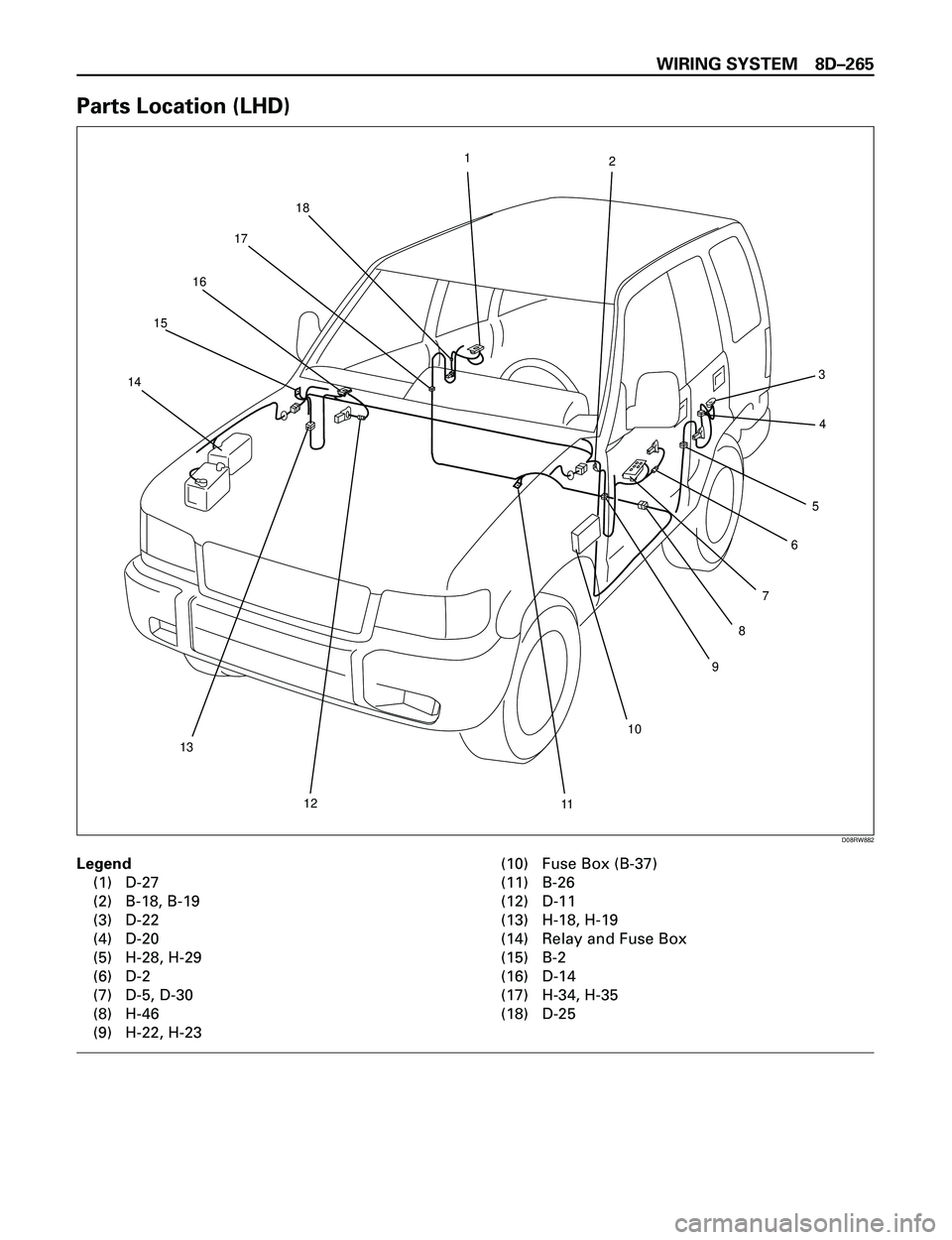
Parts Location (LHD)
Legend
(1) D-27
(2) B-18, B-19
(3) D-22
(4) D-20
(5) H-28, H-29
(6) D-2
(7) D-5, D-30
(8) H-46
(9) H-22, H-23(10) Fuse Box (B-37)
(11) B-26
(12) D-11
(13) H-18, H-19
(14) Relay and Fuse Box
(15) B-2
(16) D-14
(17) H-34, H-35
(18) D-25
2 1
18
17
16
15
14
13
12
11109 7
8654 3
D08RW882
Page 2859 of 3573
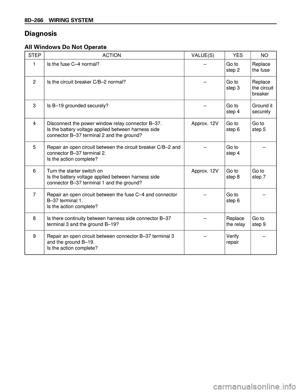
8DÐ266 WIRING SYSTEM
Diagnosis
All Windows Do Not Operate
STEP ACTION VALUE(S) YES NO
Is the fuse CÐ4 normal?
Is the circuit breaker C/BÐ2 normal?
Is BÐ19 grounded securely?
Disconnect the power window relay connector BÐ37.
Is the battery voltage applied between harness side
connector BÐ37 terminal 2 and the ground?
Repair an open circuit between the circuit breaker C/BÐ2 and
connector BÐ37 terminal 2.
Is the action complete?
Turn the starter switch on
Is the battery voltage applied between harness side
connector BÐ37 terminal 1 and the ground?
Repair an open circuit between the fuse CÐ4 and connector
BÐ37 terminal 1.
Is the action complete?
Is there continuity between harness side connector BÐ37
terminal 3 and the ground BÐ19?
Repair an open circuit between connector BÐ37 terminal 3
and the ground BÐ19.
Is the action complete?Ð
Ð
Ð
Approx. 12V
Ð
Approx. 12V
Ð
Ð
ÐGo to
step 2
Go to
step 3
Go to
step 4
Go to
step 6
Go to
step 4
Go to
step 8
Go to
step 6
Replace
the relay
Verify
repairReplace
the fuse
Replace
the circuit
breaker
Ground it
securely
Go to
step 5
Ð
Go to
step 7
Ð
Go to
step 9
Ð 1
2
3
4
5
6
7
8
9
Page 2860 of 3573
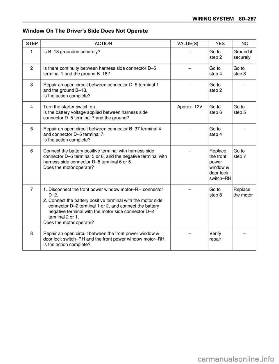
WIRING SYSTEM 8DÐ267
Window On The DriverÕs Side Does Not Operate
STEP ACTION VALUE(S) YES NO
Is BÐ18 grounded securely?
Is there continuity between harness side connector DÐ5
terminal 1 and the ground BÐ18?
Repair an open circuit between connector DÐ5 terminal 1
and the ground BÐ18.
Is the action complete?
Turn the starter switch on.
Is the battery voltage applied between harness side
connector DÐ5 terminal 7 and the ground?
Repair an open circuit between connector BÐ37 terminal 4
and connector DÐ5 terminal 7.
Is the action complete?
Connect the battery positive terminal with harness side
connector DÐ5 terminal 5 or 6, and the negative terminal with
harness side connector DÐ5 terminal 6 or 5.
Does the motor operate?
1. Disconnect the front power window motorÐRH connector
DÐ2.
2. Connect the battery positive terminal with the motor side
connector DÐ2 terminal 1 or 2, and connect the battery
negative terminal with the motor side connector DÐ2
terminal 2 or 1.
Does the motor operate?
Repair an open circuit between the front power window &
door lock switchÐRH and the front power window motorÐRH.
Is the action complete?Ð
Ð
Ð
Approx. 12V
Ð
Ð
Ð
ÐGo to
step 2
Go to
step 4
Go to
step 2
Go to
step 6
Go to
step 4
Replace
the front
power
window &
door lock
switchÐRH
Go to
step 8
Verify
repairGround it
securely
Go to
step 3
Ð
Go to
step 5
Ð
Go to
step 7
Replace
the motor
Ð 1
2
3
4
5
6
7
8