keyless entry ISUZU TROOPER 1998 Service Owner's Manual
[x] Cancel search | Manufacturer: ISUZU, Model Year: 1998, Model line: TROOPER, Model: ISUZU TROOPER 1998Pages: 3573, PDF Size: 60.36 MB
Page 2983 of 3573
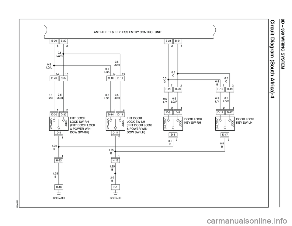
8D – 390 WIRING SYSTEM
Circuit Diagram (South Africa)-4
D08RW689
FRT DOOR
LOCK SW-RH
(FRT DOOR LOCK
& POWER WIN-
DOW SW-RH)
H-231 1D-515
H-22 14
H-226B-20
2
B-20
0.5
LG/L
0.3
LG/L
B-18 1.25
B 1.25
B
BODY-RH
ANTI-THEFT & KEYLESS ENTRY CONTROL UNIT
2
D-30
D-301
FRT DOOR
LOCK SW-LH
(FRT DOOR LOCK
& POWER WIN-
DOW SW-LH)
H-191 7D-1415
H-18 14
H-18
0.5
LG/R0.5
LG/R 0.5
LG/R
0.5
LG/R0.3
LG/L0.3
LG/L
B-1 1.25
B
2.0
B 1.25
B
BODY-LH
4
D-14
D-143
DOOR LOCK
KEY SW-RHDOOR LOCK
KEY SW-LH
2
H-23 7
H-232B-21
1
B-21
0.5
LG/R0.5
O
0.5
L/Y 0.5
G
0.5
LG/R 0.5
L/Y0.5
O 0.5
G
0.5
B
UNLOCK
LOCK
UNLOCK
LOCK UNLOCK
LOCK UNLOCK
LOCK
0.5
B
1
D-8
D-82
32H-19 7
H-19
1
D-17
D-172
3
D-8
D-17
Page 2984 of 3573
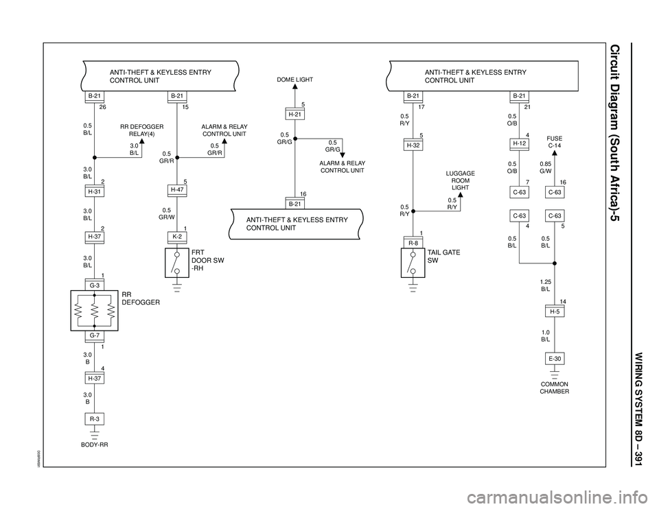
WIRING SYSTEM 8D – 391
Circuit Diagram (South Africa)-5
D08RW691
H-312
B-2116H-215
R-81H-325
2 26
0.5
B/L
3.0
B/L RR DEFOGGER
RELAY(4)
3.0
B/L
3.0
B/L
3.0
B/L
3.0
B
3.0
B
RR
DEFOGGERFRT
DOOR SW
-RHANTI-THEFT & KEYLESS ENTRY
CONTROL UNIT ANTI-THEFT & KEYLESS ENTRY
CONTROL UNITANTI-THEFT & KEYLESS ENTRY
CONTROL UNIT
B-21H-37H-374G-31
1G-7R-3
BODY-RR
H-514E-30C-63
COMMON
CHAMBER
1 15
0.5
GR/R
0.5
GR/W0.5
GR/R ALARM & RELAY
CONTROL UNITDOME LIGHT
B-21K-25H-47
0.5
GR/G
0.5
GR/G
ALARM & RELAY
CONTROL UNIT
TAIL GATE
SW
17
0.5
R/Y0.5
O/B
0.5
O/B
0.5
B/L0.85
G/W
0.5
B/L
1.25
B/L
1.0
B/L 0.5
R/Y0.5
R/Y LUGGAGE
ROOM
LIGHT
B-21
21
B-21
4H-12
5
C-63 FUSE
C-14
16
C-637C-63
4
Page 2986 of 3573
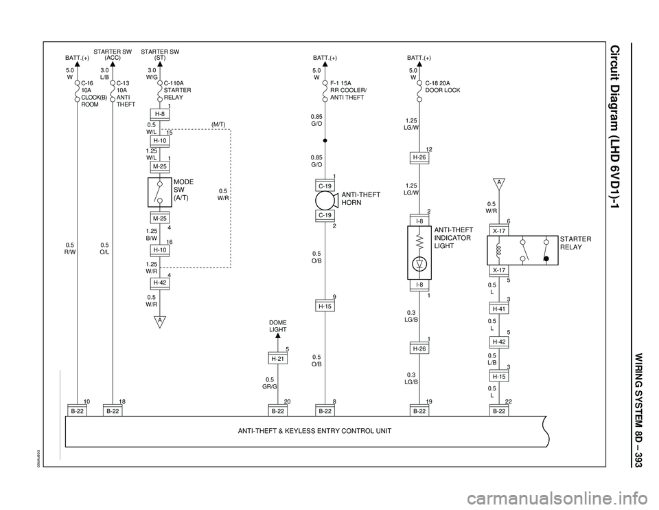
WIRING SYSTEM 8D – 393
Circuit Diagram (LHD 6VD1)-1
D08RW920
I-8
1I-82
1
H-8 3.0
L/B 5.0
W
0.5
O/L 0.5
R/WC-16
10A
CLOCK(B)
ROOMC-13
10A
ANTI
THEFTF-1 15A
RR COOLER/
ANTI THEFTC-18 20A
DOOR LOCK
MODE
SW
(A/T)ANTI-THEFT
HORN
ANTI-THEFT
INDICATOR
LIGHT
0.5
W/L
1.25
W/L
1.25
B/W
1.25
W/R
0.5
GR/G0.5
O/B
0.5
L 0.5
L/B0.5
L 0.5
L 0.5
W/R
0.5
O/B 0.85
G/O 0.85
G/O1.25
LG/W
1.25
LG/W
0.3
LG/B
0.3
LG/B 5.0
W5.0
W
(M/T)
0.5
W/R0.5
W/R BATT.(+)BATT.(+) BATT.(+) STARTER SW
(ACC)
16H-1015H-10
1M-25
B-2210
A
A
B-2218
H-424M-25
4
B-2220
B-228
B-2219
B-2222H-153H-413
H-261
H-159C-191
3.0
W/G
C-110A
STARTER
RELAY STARTER SW
(ST)
C-19
2
H-2612
H-425
H-21 DOME
LIGHT
5
ANTI-THEFT & KEYLESS ENTRY CONTROL UNITSTARTER
RELAY
5
X-17X-176
Page 2987 of 3573
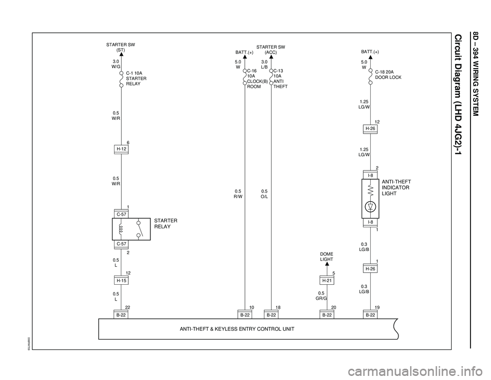
8D – 394 WIRING SYSTEM
Circuit Diagram (LHD 4JG2)-1
D08RW709
STARTER SW
(ST)
3.0
W/G
0.5
W/R0.5
W/R
0.5
L 0.5
L
STARTER
RELAYANTI-THEFT
INDICATOR
LIGHT
ANTI-THEFT & KEYLESS ENTRY CONTROL UNIT
C-1 10A
STARTER
RELAYBATT.(+)
5.0
W
0.5
R/WC-16
10A
CLOCK(B)
ROOM
1
C-57
12H-15
10
B-22 22
B-22
STARTER SW
(ACC)
3.0
L/B
0.5
O/LC-13
10A
ANTI
THEFT
18
B-2220
B-225H-21DOME
LIGHT
0.5
GR/G
19
B-221H-262I-8
1I-812H-26 BATT.(+)
0.3
LG/B0.3
LG/B1.25
LG/W1.25
LG/W5.0
W
C-18 20A
DOOR LOCK
2
C-57
6
H-12
Page 2988 of 3573
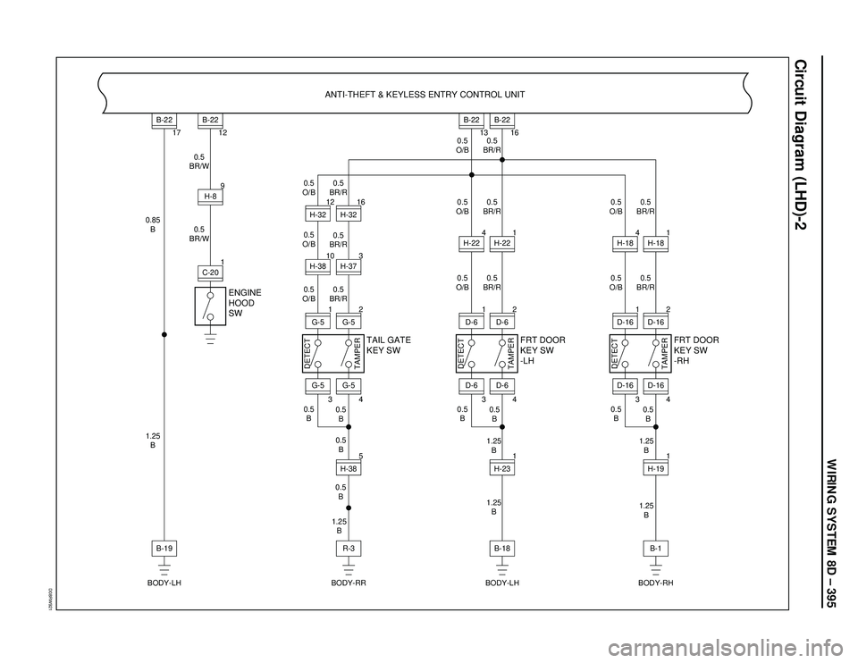
WIRING SYSTEM 8D – 395
Circuit Diagram (LHD)-2
D08RW921
ENGINE
HOOD
SWANTI-THEFT & KEYLESS ENTRY CONTROL UNIT
0.5
BR/W
0.5
BR/W 0.85
B
1.25
B0.5
O/B0.5
BR/R
0.5
BR/R
0.5
BR/R
0.5
B
0.5
B
1.25
B 0.5
B 0.5
O/B
0.5
O/B
0.5
B 1C-20
B-199
H-8
3
H-37
17
B-22
BODY-LH BODY-RR BODY-LH BODY-RH12
B-22
13
B-22
16
B-22
G-5
4G-52H-385H-3216
10
H-38G-5
3G-5
TAMPERDETECT
1
H-3212
TAIL GATE
KEY SW
R-3
0.5
O/B0.5
BR/R
0.5
BR/R
0.5
B
1.25
B
1.25
B1.25
B
1.25
B 0.5
O/B0.5
BR/R 0.5
O/B
0.5
B
D-6
4D-62H-231
D-6
3D-6
TAMPERDETECT
1
1
4
FRT DOOR
KEY SW
-LHFRT DOOR
KEY SW
-RH
B-18
0.5
BR/R
0.5
B 0.5
O/B0.5
BR/R 0.5
O/B
0.5
BD-16
4D-162H-191
1
D-16
H-22
H-22
H-18
H-18
3D-16
TAMPERDETECT
1 4
B-1
Page 2989 of 3573
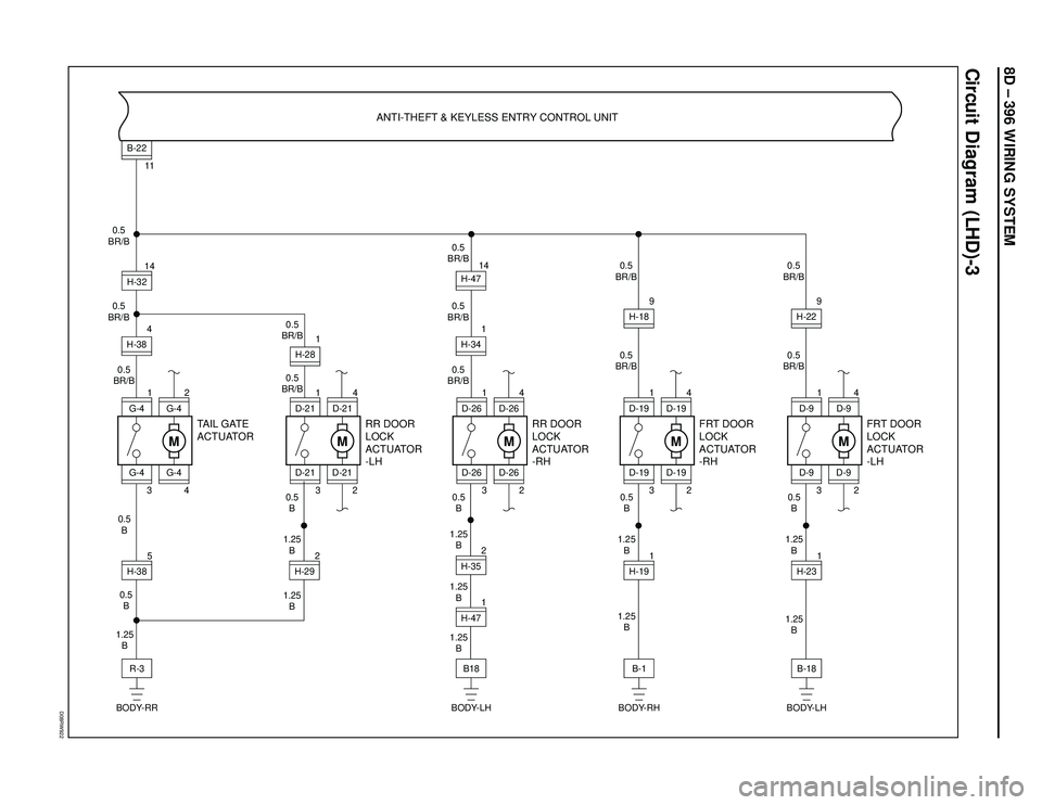
8D – 396 WIRING SYSTEM
Circuit Diagram (LHD)-3
D08RW922
M
2
4
G-4
TAIL GATE
ACTUATOR
G-41H-385 3G-44H-3811B-22
G-4
H-32 0.5
BR/B
0.5
BR/B
0.5
BR/B14R-3 0.5
B
1.25
B 0.5
B
BODY-RR
M
4
2
D-21
RR DOOR
LOCK
ACTUATOR
-LHANTI-THEFT & KEYLESS ENTRY CONTROL UNIT
1
H-352H-471 3
D-211
D-21 0.5
BR/B
0.5
BR/B
B18 1.25
B 0.5
B
1.25
B
1.25
B
BODY-LH
M
4
2
D-26
RR DOOR
LOCK
ACTUATOR
-RH
D-261
H-2923
D-26
D-26
0.5
B
1.25
B
1.25
B
M
4
2
D-19
FRT DOOR
LOCK
ACTUATOR
-RH
D-191H-191 3D-199H-18
D-19 0.5
BR/B
0.5
BR/B
B-1 0.5
B
1.25
B
1.25
B
BODY-RH
M
4
2
D-9
FRT DOOR
LOCK
ACTUATOR
-LH
D-91H-231 3D-99H-22
D-9 0.5
BR/B
0.5
BR/B
B-18 0.5
B
1.25
B
1.25
B
BODY-LH
1 14
H-34H-47
0.5
BR/B0.5
BR/B
0.5
BR/B
H-28
D-21
Page 2990 of 3573
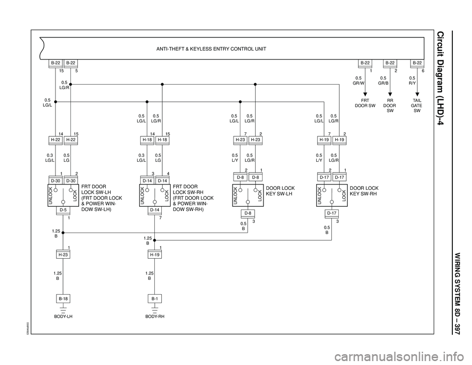
WIRING SYSTEM 8D – 397
Circuit Diagram (LHD)-4
D08RW923
FRT DOOR
LOCK SW-LH
(FRT DOOR LOCK
& POWER WIN-
DOW SW-LH)
H-231 1D-515
H-22 14
H-2215B-22
5
B-22
0.5
LG/R
0.5
LG 0.5
LG/L
0.3
LG/L
B-18 1.25
B 1.25
B
BODY-LH
ANTI-THEFT & KEYLESS ENTRY CONTROL UNIT
2
D-30
D-301
FRT DOOR
LOCK SW-RH
(FRT DOOR LOCK
& POWER WIN-
DOW SW-RH)
H-191 7D-1415
H-18 14
H-18
0.5
LG 0.3
LG/L0.5
LG/R 0.5
LG/L
B-1 1.25
B 1.25
B
BODY-RH
4
D-14
D-143
DOOR LOCK
KEY SW-LHDOOR LOCK
KEY SW-RH
2
H-23 7
H-231
0.5
GR/W0.5
GR/B0.5
R/Y
B-22
FRT
DOOR SWRR
DOOR
SWTAIL
GATE
SW
0.5
LG/R0.5
LG/R
0.5
L/Y 0.5
LG/L
0.5
LG/R 0.5
L/Y0.5
LG/R 0.5
LG/L
0.5
B
UNLOCK
LOCK
UNLOCK
LOCK UNLOCK
LOCK UNLOCK
LOCK
0.5
B
1
D-8
D-82
32H-19 7
H-19
1
D-17
D-172
3
D-8
D-17
2
B-22
6
B-22
Page 2992 of 3573
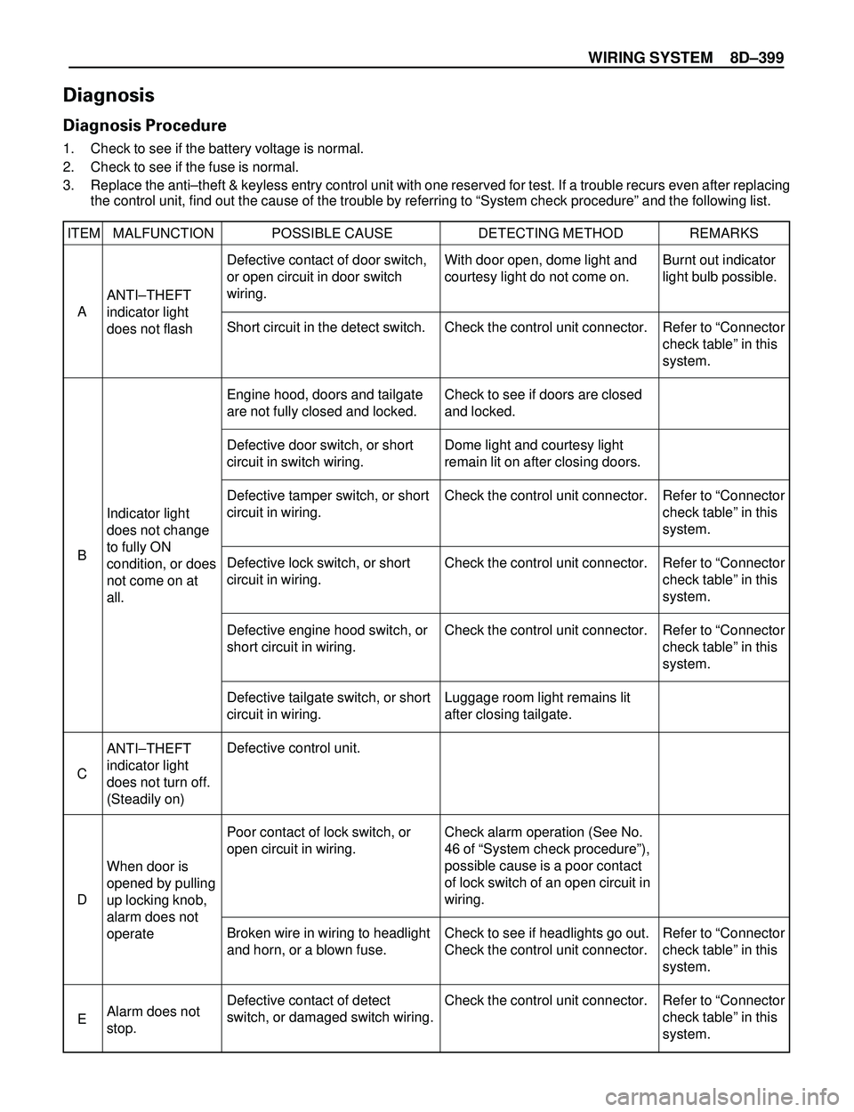
WIRING SYSTEM 8DÐ399
Diagnosis
Diagnosis Procedure
1. Check to see if the battery voltage is normal.
2. Check to see if the fuse is normal.
3. Replace the antiÐtheft & keyless entry control unit with one reserved for test. If a trouble recurs even after replacing
the control unit, find out the cause of the trouble by referring to ÒSystem check procedureÓ and the following list.
ITEM MALFUNCTION POSSIBLE CAUSE DETECTING METHOD REMARKS
ANTIÐTHEFT
indicator light
does not flash
ANTIÐTHEFT
indicator light
does not turn off.
(Steadily on)
When door is
opened by pulling
up locking knob,
alarm does not
operate
Alarm does not
stop. Indicator light
does not change
to fully ON
condition, or does
not come on at
all.Burnt out indicator
light bulb possible.
Refer to ÒConnector
check tableÓ in this
system.
Refer to ÒConnector
check tableÓ in this
system.
Refer to ÒConnector
check tableÓ in this
system.
Refer to ÒConnector
check tableÓ in this
system.
Refer to ÒConnector
check tableÓ in this
system.
Refer to ÒConnector
check tableÓ in this
system. Defective contact of door switch,
or open circuit in door switch
wiring.
Short circuit in the detect switch.
Engine hood, doors and tailgate
are not fully closed and locked.
Defective door switch, or short
circuit in switch wiring.
Defective tamper switch, or short
circuit in wiring.
Defective lock switch, or short
circuit in wiring.
Defective engine hood switch, or
short circuit in wiring.
Defective tailgate switch, or short
circuit in wiring.
Defective control unit.
Poor contact of lock switch, or
open circuit in wiring.
Broken wire in wiring to headlight
and horn, or a blown fuse.
Defective contact of detect
switch, or damaged switch wiring.With door open, dome light and
courtesy light do not come on.
Check the control unit connector.
Check to see if doors are closed
and locked.
Dome light and courtesy light
remain lit on after closing doors.
Check the control unit connector.
Check the control unit connector.
Check the control unit connector.
Luggage room light remains lit
after closing tailgate.
Check alarm operation (See No.
46 of ÒSystem check procedureÓ),
possible cause is a poor contact
of lock switch of an open circuit in
wiring.
Check to see if headlights go out.
Check the control unit connector.
Check the control unit connector. A
C
D
E B
Page 2997 of 3573
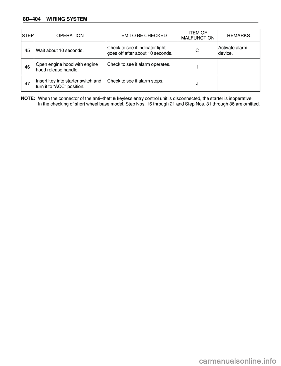
8DÐ404 WIRING SYSTEM
STEP OPERATION ITEM TO BE CHECKEDITEM OF
REMARKS
MALFUNCTION
Activate alarm
device. Check to see if indicator light
goes off after about 10 seconds.
Check to see if alarm operates.
Check to see if alarm stops. Wait about 10 seconds.
Open engine hood with engine
hood release handle.
Insert key into starter switch and
turn it to ÒACCÓ position.C
I
J 45
46
47
NOTE:When the connector of the antiÐtheft & keyless entry control unit is disconnected, the starter is inoperative.
In the checking of short wheel base model, Step Nos. 16 through 21 and Step Nos. 31 through 36 are omitted.
Page 2998 of 3573
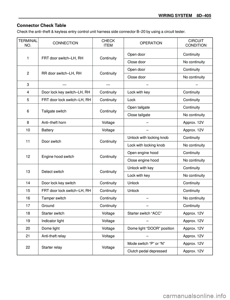
WIRING SYSTEM 8DÐ405
TERMINAL
CONNECTIONCHECK
OPERATIONCIRCUIT
NO. ITEM CONDITION
1 FRT door switchÐLH, RH ContinuityOpen door Continuity
Close door No continuity
2 RR door switchÐLH, RH ContinuityOpen door Continuity
Close door No continuity
3Ñ Ñ Ð Ð
4 Door lock key switchÐLH, RH Continuity Lock with key Continuity
5 FRT door lock switchÐLH, RH Continuity Lock Continuity
6 Tailgate switch ContinuityOpen tailgate Continuity
Close tailgate No continuity
8 AntiÐtheft horn Voltage Ð Approx. 12V
10 Battery Voltage Ð Approx. 12V
11 Door switch ContinuityUnlock with locking knob Continuity
Lock with locking knob No continuity
12 Engine hood switch ContinuityOpen engine hood Continuity
Close engine hood No continuity
13 Detect switch ContinuityUnlock with key Continuity
Lock with key No continuity
14 Door lock key switch Continuity Unlock Continuity
15 FRT door lock switchÐLH, RH Continuity Unlock Continuity
16 Tamper switch Continuity Ð No continuity
17 Ground Continuity Ð Continuity
18 Starter switch Voltage Starter switch ÒACCÓ Approx. 12V
19 Indicator light Voltage Ð Approx. 12V
20 Dome light Voltage Dome light ÒDOORÓ position Approx. 12V
21 Anti-theft relay Voltage Ð Approx. 12V
22 Starter relay VoltageMode switch ÒPÓ or ÒNÓ Approx. 12V
Clutch pedal depressed Approx. 12V
Connector Check Table
Check the antiÐtheft & keyless entry control unit harness side connector BÐ20 by using a circuit tester.