wiper fluid ISUZU TROOPER 1998 Service Repair Manual
[x] Cancel search | Manufacturer: ISUZU, Model Year: 1998, Model line: TROOPER, Model: ISUZU TROOPER 1998Pages: 3573, PDF Size: 60.36 MB
Page 2571 of 3573
8B–2WIPER/WASHER SYSTEM
Service Precaution
WARNING: I F S O E Q U IPPED WITH A
SUPPLEMENTAL RESTRAINT SYSTEM (SRS),
REFER TO THE SRS COMPONENT AND WIRING
LOCATION VIEW IN ORDER TO DETERMINE
WHETHER YOU ARE PERFORMING SERVICE ON OR
NEAR THE SRS COMPONENTS OR THE SRS
WIRING. WHEN YOU ARE PERFORMING SERVICE
ON OR NEAR THE SRS COMPONENTS OR THE SRS
WIRING, REFER TO THE SRS SERVICE
INFORMATION. FAILURE TO FOLLOW WARNINGS
COULD RESULT IN POSSIBLE AIR BAG
DEPLOYMENT, PERSONAL INJURY, OR
OTHERWISE UNNEEDED SRS SYSTEM REPAIRS.CAUTION: Always use the correct fastener in the
proper location. When you replace a fastener, use
ONLY the exact part number for that application.
ISUZU will call out those fasteners that require a
replacement after removal. ISUZU will also call out
the fasteners that require thread lockers or thread
sealant. UNLESS OTHERWISE SPECIFIED, do not
use supplemental coatings (Paints, greases, or other
corrosion inhibitors) on threaded fasteners or
fastener joint interfaces. Generally, such coatings
adversely affect the fastener torque and the joint
clamping force, and may damage the fastener. When
you install fasteners, use the correct tightening
sequence and specifications. Following these
instructions can help you avoid damage to parts and
systems.
Windshield Wiper/Washer System
General Description
The circuit consists of the starter switch, windshield wiper
& washer switch, windshield wiper motor, windshield
washer motor and windshield intermittent relay.When the wiper & washer switch is turned on with the
starter switch on, the battery voltage is applied to the
wiper motor to activate the wiper.
The washer motor squirts glass cleaning fluid while the
washer switch is being pushed. The intermittent relay is
used to control motion of the wiper.
Windshield Wiper And Washer Switch
Removal and Installation
Refer to the Lighting Switch (Combination Switch) in
Lighting System section.
Windshield Wiper Motor
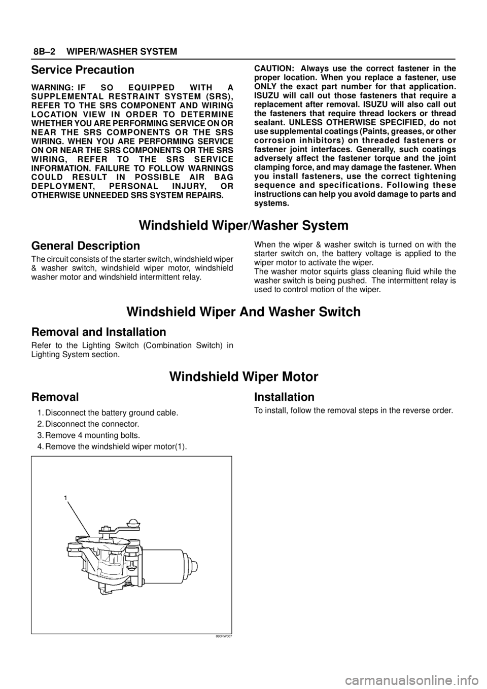
Removal
1. Disconnect the battery ground cable.
2. Disconnect the connector.
3. Remove 4 mounting bolts.
4. Remove the windshield wiper motor(1).
880RW007
Installation
To install, follow the removal steps in the reverse order.
Page 2576 of 3573
WIPER/WASHER SYSTEM8B–7
Rear Wiper/Washer System
General Description
The circuit consists of the starter switch, rear wiper &
washer switch, rear wiper motor, rear washer motor and
rear intermittent relay.When the wiper & washer switch is turned on with the
starter switch on, the battery voltage is applied to the
wiper motor to activate the wiper.
The washer motor squirts glass cleaning fluid while the
washer switch is being pushed. The intermittent relay is
used to control motion of the wiper.
Rear Wiper and Washer Switch
Removal
1. Disconnect the battery ground cable.
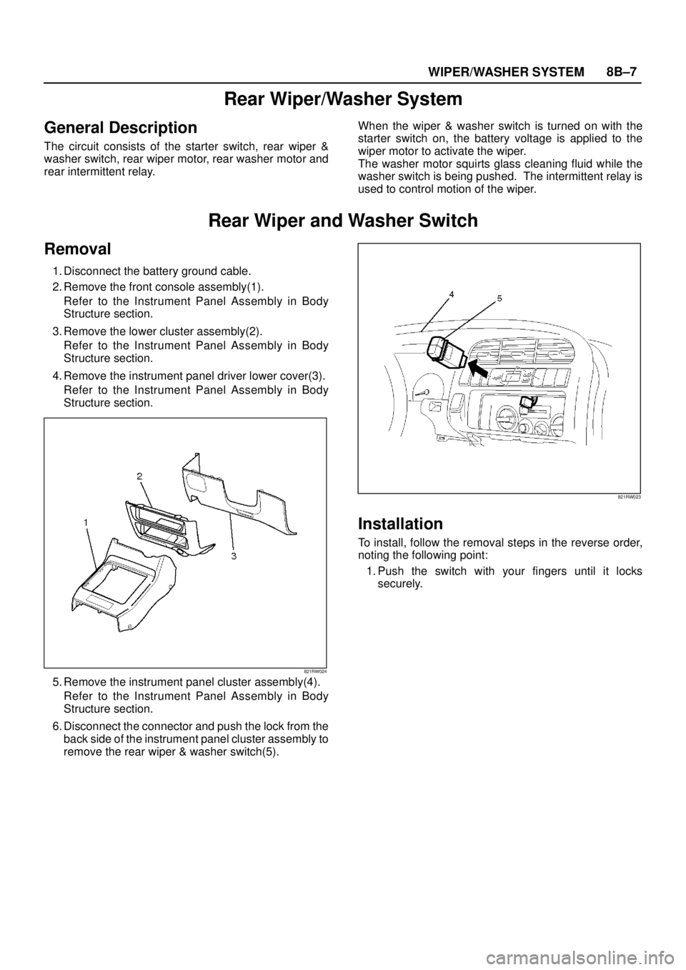
2. Remove the front console assembly(1).
Refer to the Instrument Panel Assembly in Body
Structure section.
3. Remove the lower cluster assembly(2).
Refer to the Instrument Panel Assembly in Body
Structure section.
4. Remove the instrument panel driver lower cover(3).
Refer to the Instrument Panel Assembly in Body
Structure section.
821RW024
5. Remove the instrument panel cluster assembly(4).
Refer to the Instrument Panel Assembly in Body
Structure section.
6. Disconnect the connector and push the lock from the
back side of the instrument panel cluster assembly to
remove the rear wiper & washer switch(5).
821RW023
Installation
To install, follow the removal steps in the reverse order,
noting the following point:
1. Push the switch with your fingers until it locks
securely.
Page 2579 of 3573
8B–10WIPER/WASHER SYSTEM
Rear Wiper Arm/Blade
Removal
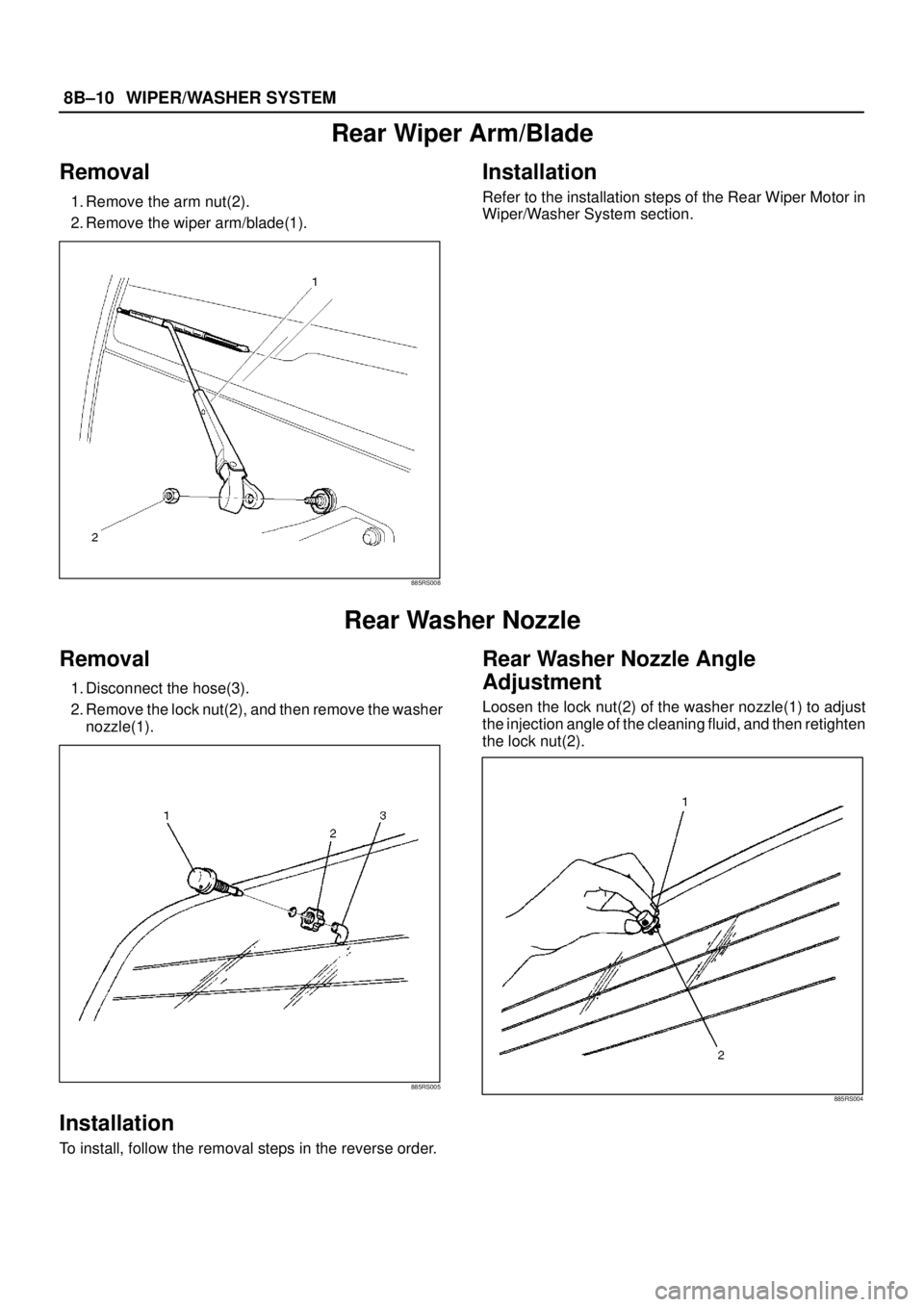
1. Remove the arm nut(2).
2. Remove the wiper arm/blade(1).
885RS008
Installation
Refer to the installation steps of the Rear Wiper Motor in
Wiper/Washer System section.
Rear Washer Nozzle
Removal
1. Disconnect the hose(3).
2. Remove the lock nut(2), and then remove the washer
nozzle(1).
885RS005
Installation
To install, follow the removal steps in the reverse order.
Rear Washer Nozzle Angle
Adjustment
Loosen the lock nut(2) of the washer nozzle(1) to adjust
the injection angle of the cleaning fluid, and then retighten
the lock nut(2).
885RS004
Page 2627 of 3573
8DÐ34 WIRING SYSTEM
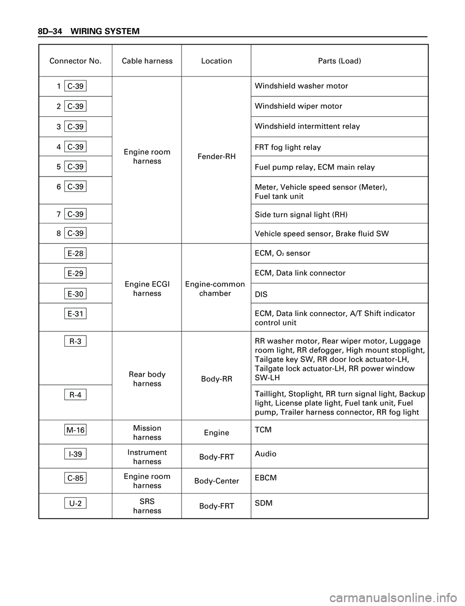
Connector No. Cable harness Location Parts (Load)
C-39
Windshield washer motor1
C-39
Windshield wiper motor2
C-39
FRT fog light relay4
C-39Meter, Vehicle speed sensor (Meter),
Fuel tank unit 6
Engine room
harnessFender-RH
E-28
ECM, O2 sensor
E-29ECM, Data link connector
Engine ECGI
harnessEngine-common
chamber
R-3
RR washer motor, Rear wiper motor, Luggage
room light, RR defogger, High mount stoplight,
Tailgate key SW, RR door lock actuator-LH,
Tailgate lock actuator-LH, RR power window
SW-LH
R-4Taillight, Stoplight, RR turn signal light, Backup
light, License plate light, Fuel tank unit, Fuel
pump, Trailer harness connector, RR fog light Rear body
harnessBody-RR
E-30
E-31ECM, Data link connector, A/T Shift indicator
control unit DIS
C-39Fuel pump relay, ECM main relay 5
C-39Windshield intermittent relay3
M-16
TCMMission
harnessEngine
C-39Side turn signal light (RH) 7
C-39Vehicle speed sensor, Brake fluid SW 8
I-39
AudioInstrument
harnessBody-FRT
C-85
EBCMEngine room
harnessBody-Center
U-2
SDMSRS
harnessBody-FRT
Page 2631 of 3573
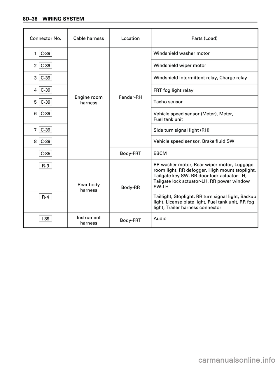
8DÐ38 WIRING SYSTEM
Connector No. Cable harness Location Parts (Load)
C-39
Windshield washer motor1
C-39
Windshield wiper motor2
C-39
FRT fog light relay4
C-39Vehicle speed sensor (Meter), Meter,
Fuel tank unit 6
Engine room
harnessFender-RH
R-3
RR washer motor, Rear wiper motor, Luggage
room light, RR defogger, High mount stoplight,
Tailgate key SW, RR door lock actuator-LH,
Tailgate lock actuator-LH, RR power window
SW-LH
R-4Taillight, Stoplight, RR turn signal light, Backup
light, License plate light, Fuel tank unit, RR fog
light, Trailer harness connector Rear body
harnessBody-RR
C-39Tacho sensor
5C-39
Windshield intermittent relay, Charge relay3
C-39Side turn signal light (RH) 7
C-39Vehicle speed sensor, Brake fluid SW
8
I-39
Audio Instrument
harnessBody-FRT C-85
EBCMBody-FRT
Page 2632 of 3573
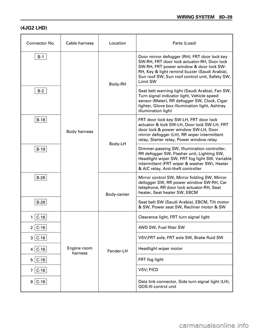
WIRING SYSTEM 8DÐ39
(4JG2 LHD)
Connector No. Cable harness Location Parts (Load)
B-1
Door mirror defogger (RH), FRT door lock key
SW-RH, FRT door lock actuator-RH, Door lock
SW-RH, FRT power window & door lock SW-
RH, Key & light remind buzzer (Saudi Arabia),
Sun roof SW, Sun roof control unit, Safety SW,
Limit SW
B-2Seat belt warning light (Saudi Arabia), Fan SW,
Turn signal indicator light, Vehicle speed
sensor (Meter), RR defogger SW, Clock, Cigar
lighter, Glove box illumination light, Ashtray
illumination light
Body-RH
B-18
FRT door lock key SW-LH, FRT door lock
actuator & lock SW-LH, Door lock SW-LH, FRT
door lock & power window SW-LH, Door
mirror defogger (LH), RR wiper intermittent
relay, Starter relay, Power window relay
B-19
B-26Mirror control SW, Mirror folding SW, Mirror
defogger SW, RR power window SW-RH, Car
telephone, RR door lock actuator-RH, Seat
heater, Seat heater SW, EBCM Body-LH Body harness
Body-center
C-16
4WD SW, Fuel filter SW2
C-16
VSV;FRT axle, FRT axle SW, Brake fluid SW3
C-16
FRT fog light 4
C-16VSV; FICD7
C-16
Data link connector, Side turn signal light (LH),
QOS-III control unit 8Fender-LH Engine room
harnessDimmer·passing SW, Illumination controller,
RR defogger SW, Flasher unit, Lighting SW,
Headlight wiper SW, FRT fog light SW, Variable
intermittent (FRT wiper & washer SW), Heater
& A/C relay, Anti-theft controller
C-16
5
Headlight wiper motor
C-16Clearance light, FRT turn signal light1B-28
Seat belt SW (Saudi Arabia), EBCM, Tilt motor
& SW, Power seat SW, Recliner motor & SW
Page 2896 of 3573
WIRING SYSTEM 8DÐ303
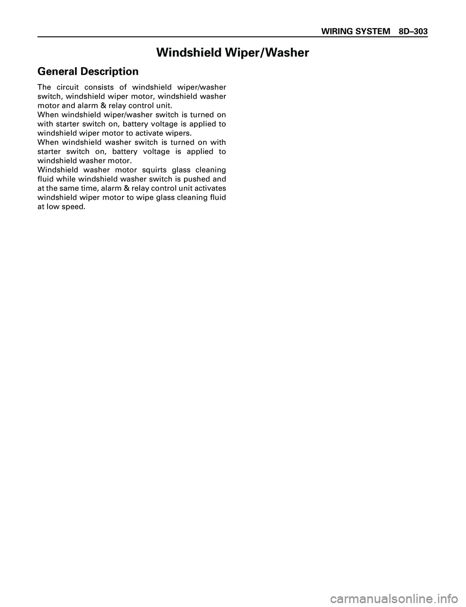
Windshield Wiper/Washer
General Description
The circuit consists of windshield wiper/washer
switch, windshield wiper motor, windshield washer
motor and alarm & relay control unit.
When windshield wiper/washer switch is turned on
with starter switch on, battery voltage is applied to
windshield wiper motor to activate wipers.
When windshield washer switch is turned on with
starter switch on, battery voltage is applied to
windshield washer motor.
Windshield washer motor squirts glass cleaning
fluid while windshield washer switch is pushed and
at the same time, alarm & relay control unit activates
windshield wiper motor to wipe glass cleaning fluid
at low speed.
Page 2909 of 3573
8DÐ316 WIRING SYSTEM
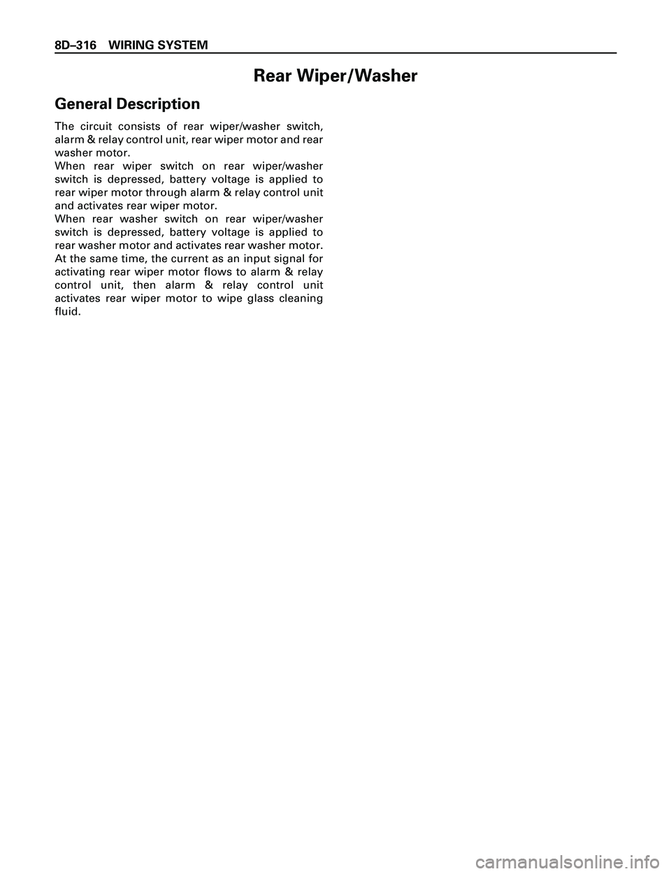
Rear Wiper/Washer
General Description
The circuit consists of rear wiper/washer switch,
alarm & relay control unit, rear wiper motor and rear
washer motor.
When rear wiper switch on rear wiper/washer
switch is depressed, battery voltage is applied to
rear wiper motor through alarm & relay control unit
and activates rear wiper motor.
When rear washer switch on rear wiper/washer
switch is depressed, battery voltage is applied to
rear washer motor and activates rear washer motor.
At the same time, the current as an input signal for
activating rear wiper motor flows to alarm & relay
control unit, then alarm & relay control unit
activates rear wiper motor to wipe glass cleaning
fluid.