ISUZU TROOPER 1998 Service Repair Manual
TROOPER 1998
ISUZU
ISUZU
https://www.carmanualsonline.info/img/61/57184/w960_57184-0.png
ISUZU TROOPER 1998 Service Repair Manual
Trending: manual transmission, brake system diagram, maintenance, seats, phone, rear entertainment, battery location
Page 3241 of 3573
8F±46BODY STRUCTURE
A10RW029
Page 3242 of 3573
8F±47 BODY STRUCTURE
A10RW013
Page 3243 of 3573
8F±48BODY STRUCTURE
Instrument Panel Assembly
Parts Location
This illustration is based on RHD and W/SRS.
740RW123
Legend
(1) Front Defroster Grille
(2) Vent Duct Assembly
(3) Instrument Harness Assembly
(4) Side Defroster Grille
(5) Meter Assembly
(6) Instrument Panel Cluster Assembly
(7) Driver Knee Bolster Assembly (W/SRS)
(8) Instrument Panel Driver Lower Cover
Assembly
(9) Radio Assembly(10) Lower Cluster Assembly
(11) Front Console Assembly
(12) Glove Box
(13) Instrument Panel Passenger Lower Cover
Assembly
(14) Passenger Knee Bolster Reinforcement
Assembly
(15) Control Lever Assembly
(16) Passenger Inflator Module (W/SRS)
(17) Instrument Panel Assembly
Page 3244 of 3573
8F±49 BODY STRUCTURE
Removal
CAUTION: F o r p recautions on installation or
removal of SRSÐair bag system, refer to
Supplemental Restraint System (SRS) Ð AIR BAG in
Restraint section.
1. Disconnect the battery ground cable.
2. Remove front console assembly.
�Remove the 4 fixing screws and disconnect the
switch connectors.
3. Remove lower cluster assembly.
�Remove the 3 fixing screws (1) in order to
disconnect the cigarette lighter (3) and the
illumination (2) connectors.
740RS014
4. Remove glove box.
�Remove the 2 fixing screws.
740RW104
5. Remove instrument panel passenger lower cover
assembly.
�Remove the 7 fixing screws (1) and 1 clip (2).
740RW103
6. Remove passenger knee bolster reinforcement
assembly.
�Remove the 4 fixing bolts (2) and 4 nuts (1).
740RS011
Page 3245 of 3573
, 1 fixing bolt (3), and
1 clip (4). Pull out")
8F±50BODY STRUCTURE
7. Remove instrument panel driver lower cover
assembly.
�Remove the engine hood opener fixing screws.
�Remove the 2 fixing screws (2), 1 fixing bolt (3), and
1 clip (4). Pull out the fasteners at the 4 positions
(1).
740RW105
8. Remove driver knee bolster assembly (W/SRS).
�Remove the 6 fixing nuts.
740RW122
9. Remove front defroster grille.
�Pry 8 claws on the front side toward you side (room
side) and raise the grille upward.
10. Remove instrument panel assembly.
�Remove the 2 fixing bolts on the SRS adjust bracket
and the cross beam under the passenger inflator
module (W/SRS).
CAUTION: F o r p recautions on installation or
removal of SRS Ð air bag system, refer to
Supplemental RestraintSystem (SRS) Ð AIR BAG in
Restraint section.
827RW031
�Disconnect the 3 air conditioner control cables on
the unit side.
�Remove the instrument harness connectors (5
connectors on the drivers side and 3 connectors on
the passenger side), the passenger inflator module
connector, the radio antenna cable plug, and the
ground cable fixing bolt on the center bracket.
�Remove the 4 bolts (4) and the 2 nuts (3) under the
instrument panel assembly, and the upper left and
the upper right bolts (2) and the center nut (1).
Page 3246 of 3573
8F±51 BODY STRUCTURE
740RW106
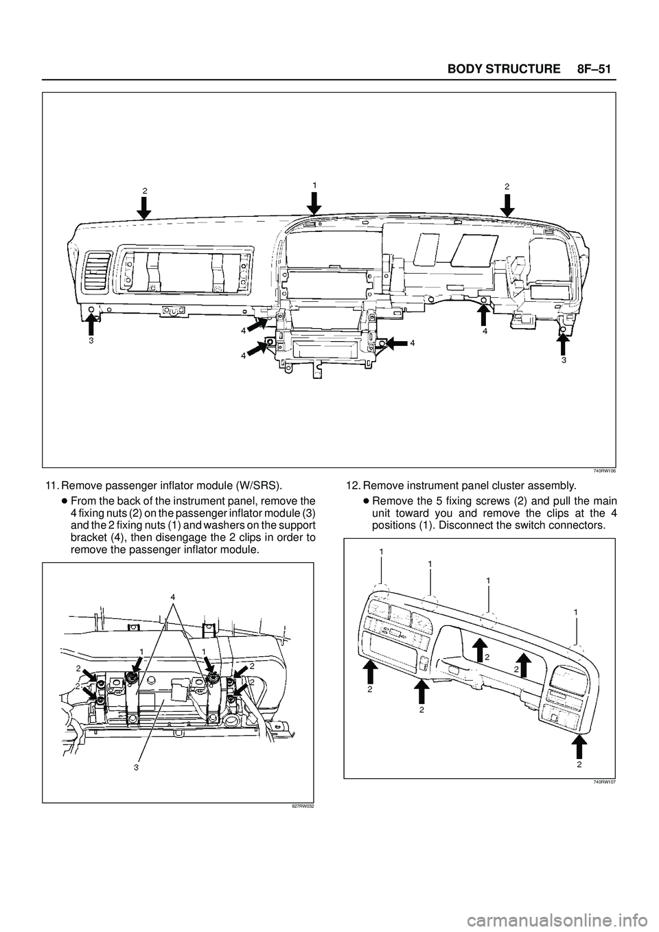
11. Remove passenger inflator module (W/SRS).
�From the back of the instrument panel, remove the
4 fixing nuts (2) on the passenger inflator module (3)
and the 2 fixing nuts (1) and washers on the support
bracket (4), then disengage the 2 clips in order to
remove the passenger inflator module.
827RW032
12. Remove instrument panel cluster assembly.
�Remove the 5 fixing screws (2) and pull the main
unit toward you and remove the clips at the 4
positions (1). Disconnect the switch connectors.
740RW107
Page 3247 of 3573
8F±52BODY STRUCTURE
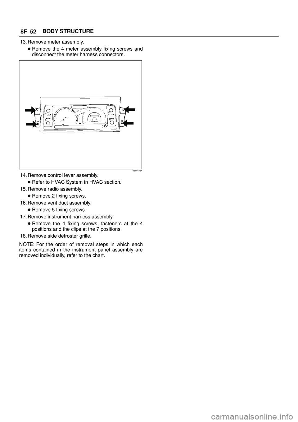
13. Remove meter assembly.
�Remove the 4 meter assembly fixing screws and
disconnect the meter harness connectors.
821RS034
14. Remove control lever assembly.
�Refer to HVAC System in HVAC section.
15. Remove radio assembly.
�Remove 2 fixing screws.
16. Remove vent duct assembly.
�Remove 5 fixing screws.
17. Remove instrument harness assembly.
�Remove the 4 fixing screws, fasteners at the 4
positions and the clips at the 7 positions.
18. Remove side defroster grille.
NOTE: For the order of removal steps in which each
items contained in the instrument panel assembly are
removed individually, refer to the chart.
Page 3248 of 3573

8F±53 BODY STRUCTURE
Installation
To install, follow the removal steps in the reverse order.
Order Of Removal/Installation Steps For Each Item
Removal Item
Removal ProcedureRemoval Step
Front console assem-
blyShift knob (M/T), Power & Winter SW (A/T), Transfer knob, Seat
heater/Miller SW conn. and 4 screws1, 2
Lower cluster assem-
bly3 screws, Ciger lighter conn. and Ashtray illumination conn.1~3
Glove box2 screws4
Instrument panel pas-
senger lower cover7 screws and 1 clip1~5
Passenger knee bol-
ster reinforcement4 nuts and 4 bolts1~6
Instrument panel driver
lower coverEngine hood opening fixing screw, 2 screws, 1 bolt, 1 clip and fasten-
ers at 4 positions1~3, 7
Driver knee bolster6 nuts1~3, 7, 8
Front defroster grilleClaws at 8 positions9
Instrument panel as-
sembly2 bolts (SRS adjust bracket~ cross beam), A/C control cable (Unit
side at 3 position), Instrument harness connector (Driver side 5 posi-
tion, assist side 3 position), SRS module conn., Radio antenna jack,
Earth cable, 9 bolts and 3 nuts1~10
Passenger inflator
module4 nuts (SRS module~Instrument panel), 2 nuts 0 and 2 washers
(SRS module~support bracket) and 2 clips1~6, 11
Instrument panel clus-
ter5 Screws, fastener at 4 position and each SW conn.1~3, 7, 12
Meter assembly4 screws and connectors1~3, 7, 12, 13
A/C control panel as-
sembly4 screws and connectors1~3, 7, 12, 14
Radio assembly2 screws1~3, 15
Vent duct assembly5 screws1~10, 16
Instrument harness as-
sembly4 screws, fasteners at 4 position, and clips at 7 position1~10, 17
Side defroster grille18
M/T = Manual Transmission
A/T = Automatic Transmission
SRS = Supplemental Restraint System
A/C = Air Conditioning
Page 3249 of 3573
 Instrument Panel Assembly
(2) Cross Beam Assembly
(3) Side Support Bracket Assem")
8F±54BODY STRUCTURE
Cross Beam Assembly
Parts Location
This illustration es based on RHD and W/SRS
740RW100
Legend
(1) Instrument Panel Assembly
(2) Cross Beam Assembly
(3) Side Support Bracket Assembly (RH)
(4) Brake Pedal Mounting Bracket Assembly(5) Steering Support Bracket Assembly
(6) Instrument Panel Center Bracket
(7) Side Support Bracket Assembly (LH)
(8) Steering Column Fixing Bolts
(9) Cross Beam Center Bracket
Removal
1. Disconnect battery ground cable.
2. Remove instrument panel assembly.
�Refer to Instrument Panel Assembly in this section.
3. Remove side support bracket assembly (LH/RH).
�Remove the 4 fixing bolts on both sides.
4. Remove cross beam center bracket
�Remove 2 fixing nuts.5. Remove instrument panel center bracket.
�Disconnect the PCM and EBCM connector.
�Remove the DERM (SRS) with 3 fixing nuts.
CAUTION: F o r p recautions on installation or
removal of SRS Ð air bag system, refer to
Supplemental Restraint System (SRS) Ð AIR BAG in
Restraint section.
�Remove the 2 fixing nuts (upper) and the 4 fixing
bolts (lower).
Page 3250 of 3573
8F±55 BODY STRUCTURE
740RW101
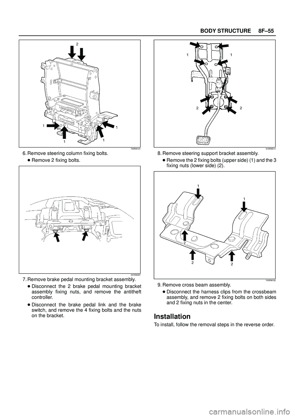
6. Remove steering column fixing bolts.
�Remove 2 fixing bolts.
431RW007
7. Remove brake pedal mounting bracket assembly.
�Disconnect the 2 brake pedal mounting bracket
assembly fixing nuts, and remove the antitheft
controller.
�Disconnect the brake pedal link and the brake
switch, and remove the 4 fixing bolts and the nuts
on the bracket.
310RW014
8. Remove steering support bracket assembly.
�Remove the 2 fixing bolts (upper side) (1) and the 3
fixing nuts (lower side) (2).
740RW102
9. Remove cross beam assembly.
�Disconnect the harness clips from the crossbeam
assembly, and remove 2 fixing bolts on both sides
and 2 fixing nuts in the center.
Installation
To install, follow the removal steps in the reverse order.
Trending: service schedule, sunroof, air condition, engine, cruise control, remote control, fuel consumption


 Front Defroster Grille
(2) Vent Duct Assembly
(3) Instrument Harness Asse")
 Ð AIR BAG in
Restraint section.
1. Disconnect")