check engine ISUZU TROOPER 1998 Service Repair Manual
[x] Cancel search | Manufacturer: ISUZU, Model Year: 1998, Model line: TROOPER, Model: ISUZU TROOPER 1998Pages: 3573, PDF Size: 60.36 MB
Page 1528 of 3573
00 Ð 28 SERVICE INFORMATION
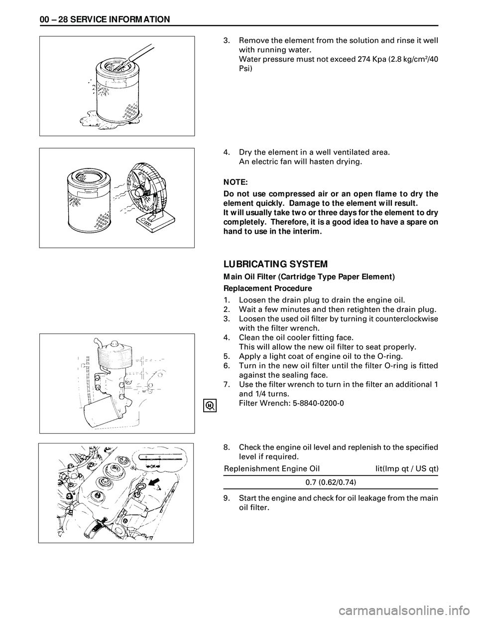
3. Remove the element from the solution and rinse it well
with running water.
Water pressure must not exceed 274 Kpa (2.8 kg/cm
2/40
Psi)
4. Dry the element in a well ventilated area.
An electric fan will hasten drying.
NOTE:
Do not use compressed air or an open flame to dry the
element quickly. Damage to the element will result.
It will usually take two or three days for the element to dry
completely. Therefore, it is a good idea to have a spare on
hand to use in the interim.
LUBRICATING SYSTEM
Main Oil Filter (Cartridge Type Paper Element)
Replacement Procedure
1. Loosen the drain plug to drain the engine oil.
2. Wait a few minutes and then retighten the drain plug.
3. Loosen the used oil filter by turning it counterclockwise
with the filter wrench.
4. Clean the oil cooler fitting face.
This will allow the new oil filter to seat properly.
5. Apply a light coat of engine oil to the O-ring.
6. Turn in the new oil filter until the filter O-ring is fitted
against the sealing face.
7. Use the filter wrench to turn in the filter an additional 1
and 1/4 turns.
Filter Wrench: 5-8840-0200-0
8. Check the engine oil level and replenish to the specified
level if required.
0.7 (0.62/0.74)
lit(Imp qt / US qt) Replenishment Engine Oil
9. Start the engine and check for oil leakage from the main
oil filter.
Page 1529 of 3573
SERVICE INFORMATION 00 Ð 29
FUEL SYSTEM
Fuel Filter
Replacement Procedure
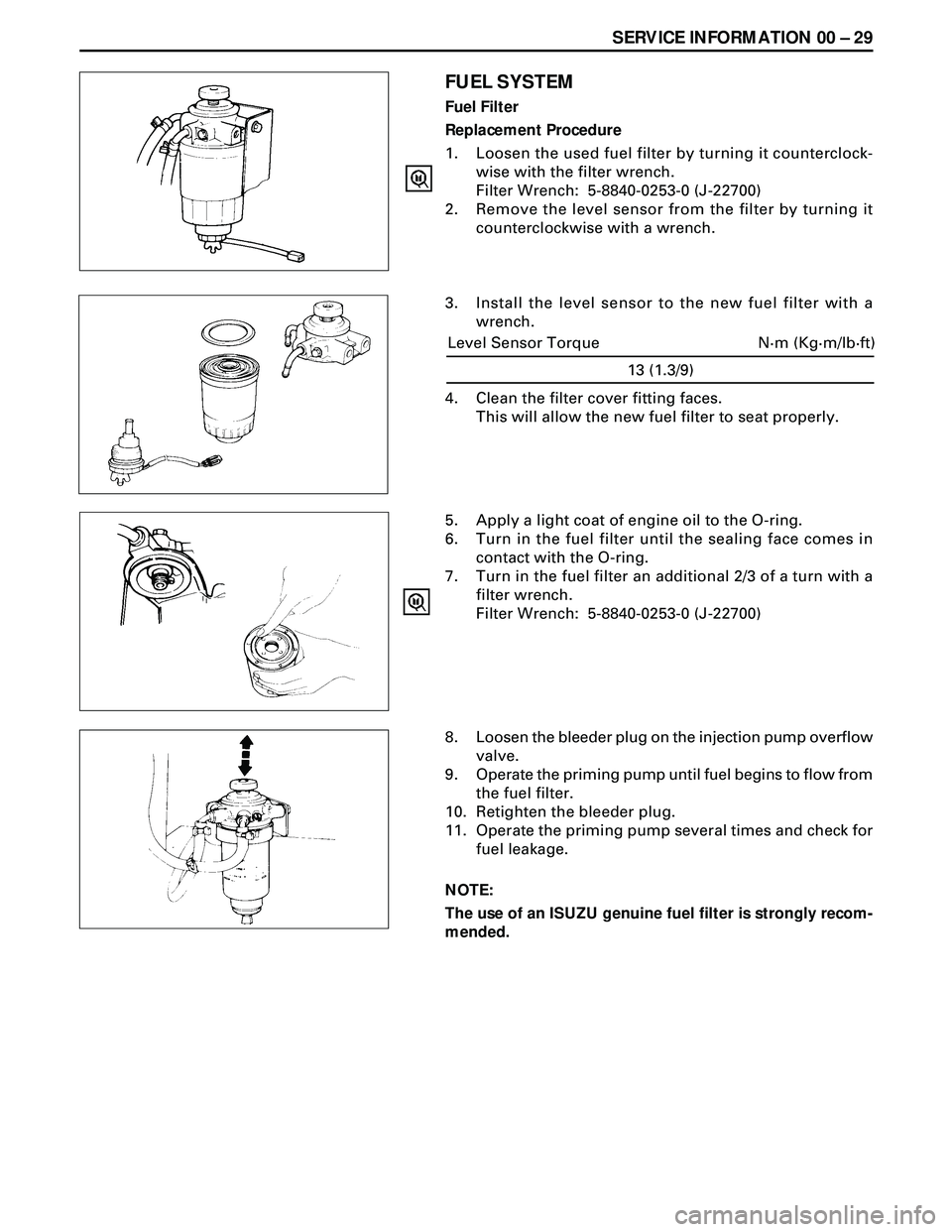
1. Loosen the used fuel filter by turning it counterclock-
wise with the filter wrench.
Filter Wrench: 5-8840-0253-0 (J-22700)
2. Remove the level sensor from the filter by turning it
counterclockwise with a wrench.
3. Install the level sensor to the new fuel filter with a
wrench.
5. Apply a light coat of engine oil to the O-ring.
6. Turn in the fuel filter until the sealing face comes in
contact with the O-ring.
7. Turn in the fuel filter an additional 2/3 of a turn with a
filter wrench.
Filter Wrench: 5-8840-0253-0 (J-22700)
8. Loosen the bleeder plug on the injection pump overflow
valve.
9. Operate the priming pump until fuel begins to flow from
the fuel filter.
10. Retighten the bleeder plug.
11. Operate the priming pump several times and check for
fuel leakage.
NOTE:
The use of an ISUZU genuine fuel filter is strongly recom-
mended.
13 (1.3/9)
N·m (Kg·m/lb·ft) Level Sensor Torque
4. Clean the filter cover fitting faces.
This will allow the new fuel filter to seat properly.
Page 1530 of 3573
00 Ð 30 SERVICE INFORMATION
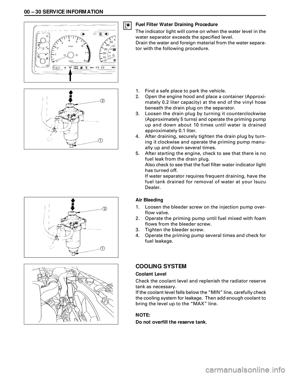
Fuel Filter Water Draining Procedure
The indicator light will come on when the water level in the
water separator exceeds the specified level.
Drain the water and foreign material from the water separa-
tor with the following procedure.
1. Find a safe place to park the vehicle.
2. Open the engine hood and place a container (Approxi-
mately 0.2 liter capacity) at the end of the vinyl hose
beneath the drain plug on the separator.
3. Loosen the drain plug by turning it counterclockwise
(Approximately 5 turns) and operate the priming pump
up and down about 10 times until water is drained
approximately 0.1 liter.
4. After draining, securely tighten the drain plug by turn-
ing it clockwise and operate the priming pump manu-
ally up and down several times.
5. After starting the engine, check to see that there is no
fuel leak from the drain plug.
Also check to see that the fuel filter water indicator light
has turned off.
If water separator requires frequent draining, have the
fuel tank drained for removal of water at your Isuzu
Dealer.
Air Bleeding
1. Loosen the bleeder screw on the injection pump over-
flow valve.
2. Operate the priming pump until fuel mixed with foam
flows from the bleeder screw.
3. Tighten the bleeder screw.
4. Operate the priming pump several times and check for
fuel leakage.
COOLING SYSTEM
Coolant Level
Check the coolant level and replenish the radiator reserve
tank as necessary.
If the coolant level falls below the ÒMINÓ line, carefully check
the cooling system for leakage. Then add enough coolant to
bring the level up to the ÒMAXÓ line.
NOTE:
Do not overfill the reserve tank.
Page 1531 of 3573
SERVICE INFORMATION 00 Ð 31
Remove the radiator filler cap only when absolutely neces-
sary.
Always check the coolant level when the engine is cold.
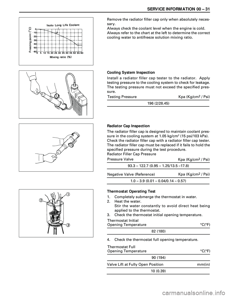
Always refer to the chart at the left to determine the correct
cooling water to antifreeze solution mixing ratio.
Cooling System Inspection
Install a radiator filler cap tester to the radiator. Apply
testing pressure to the cooling system to check for leakage.
The testing pressure must not exceed the specified pres-
sure.
Radiator Cap Inspection
The radiator filler cap is designed to maintain coolant pres-
sure in the cooling system at 1.05 kg/cm
2 (15 psi/103 kPa).
Check the radiator filler cap with a radiator filler cap tester.
The radiator filler cap must be replaced if it fails to hold the
specified pressure during the test procedure.
Radiator Filler Cap Pressure
Thermostat Operating Test
1. Completely submerge the thermostat in water.
2. Heat the water.
Stir the water constantly to avoid direct heat being
applied to the thermostat.
3. Check the thermostat initial opening temperature.
82 (180)
°C(°F) Thermostat Initial
Opening Temperature
4. Check the thermostat full opening temperature.
1.0 – 3.9 (0.01 – 0.04/0.14 – 0.57)
Negative Valve (Reference)Kpa (Kg/cm2 / Psi)
90 (194)
°C(°F) Thermostat Full
Opening Temperature
10 (0.39)
mm(in) Valve Lift at Fully Open Position
196 (2/28.45)
Testing Pressure Kpa (Kg/cm2 / Psi)
93.3 – 122.7 (0.95 – 1.25/13.5 –17.8)
Pressure Valve
Kpa (Kg/cm2 / Psi)
Page 1533 of 3573
SERVICE INFORMATION 00 Ð 33
ENGINE CONTROL
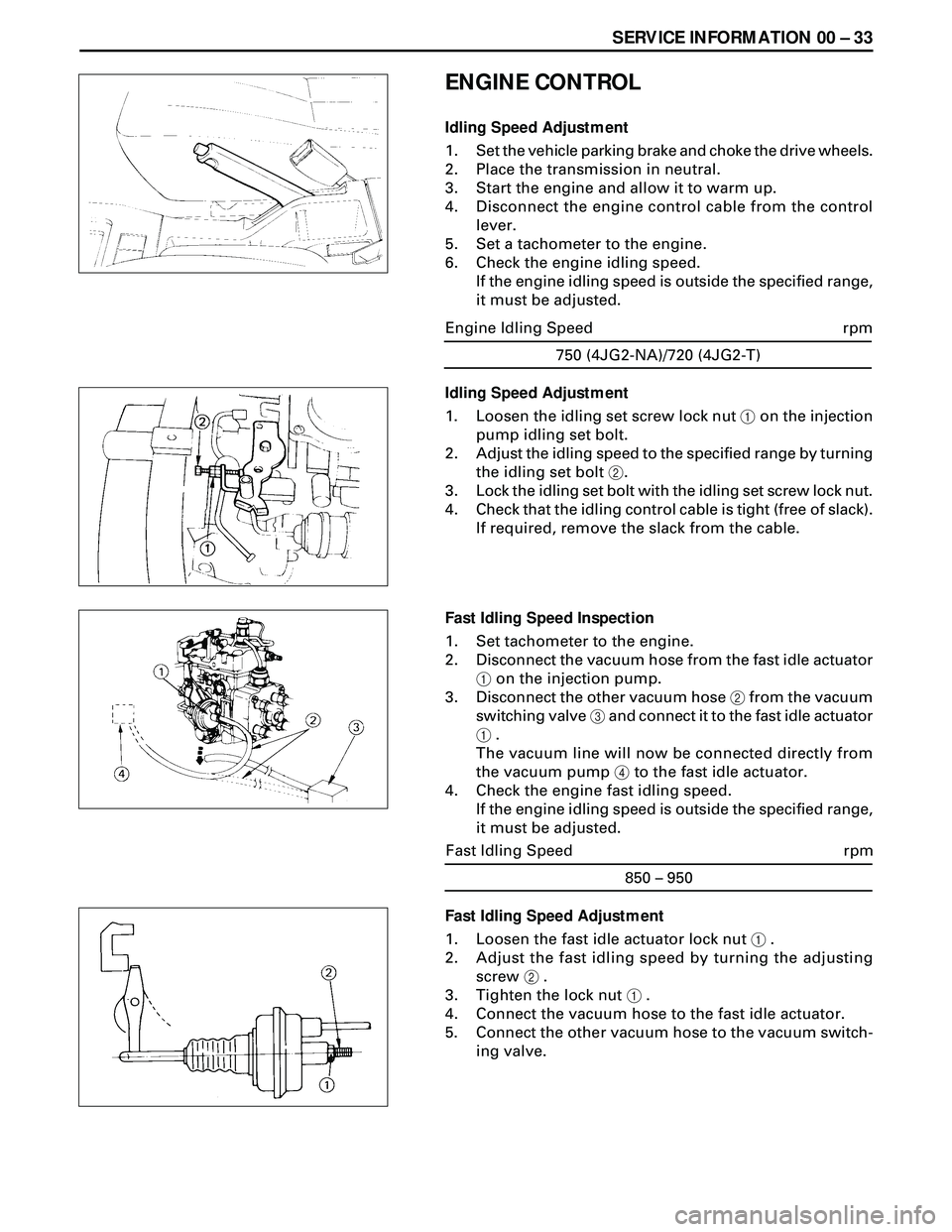
Idling Speed Adjustment
1. Set the vehicle parking brake and choke the drive wheels.
2. Place the transmission in neutral.
3. Start the engine and allow it to warm up.
4. Disconnect the engine control cable from the control
lever.
5. Set a tachometer to the engine.
6. Check the engine idling speed.
If the engine idling speed is outside the specified range,
it must be adjusted.
Fast Idling Speed Adjustment
1. Loosen the fast idle actuator lock nut 1 .
2. Adjust the fast idling speed by turning the adjusting
screw 2 .
3. Tighten the lock nut 1 .
4. Connect the vacuum hose to the fast idle actuator.
5. Connect the other vacuum hose to the vacuum switch-
ing valve.750 (4JG2-NA)/720 (4JG2-T)
rpm Engine Idling Speed
Idling Speed Adjustment
1. Loosen the idling set screw lock nut 1 on the injection
pump idling set bolt.
2. Adjust the idling speed to the specified range by turning
the idling set bolt 2.
3. Lock the idling set bolt with the idling set screw lock nut.
4. Check that the idling control cable is tight (free of slack).
If required, remove the slack from the cable.
Fast Idling Speed Inspection
1. Set tachometer to the engine.
2. Disconnect the vacuum hose from the fast idle actuator
1 on the injection pump.
3. Disconnect the other vacuum hose 2 from the vacuum
switching valve 3 and connect it to the fast idle actuator
1 .
The vacuum line will now be connected directly from
the vacuum pump 4 to the fast idle actuator.
4. Check the engine fast idling speed.
If the engine idling speed is outside the specified range,
it must be adjusted.
850 – 950
rpm Fast Idling Speed
Page 1534 of 3573
00 Ð 34 SERVICE INFORMATION
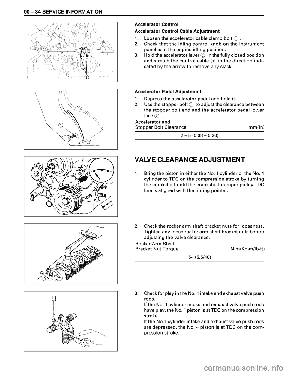
Accelerator Control
Accelerator Control Cable Adjustment
1. Loosen the accelerator cable clamp bolt 1 .
2. Check that the idling control knob on the instrument
panel is in the engine idling position.
3. Hold the accelerator lever 2 in the fully closed position
and stretch the control cable 3 in the direction indi-
cated by the arrow to remove any slack.
Accelerator Pedal Adjustment
1. Depress the accelerator pedal and hold it.
2. Use the stopper bolt 1 to adjust the clearance between
the stopper bolt end and the accelerator pedal lower
face 2 .
VALVE CLEARANCE ADJUSTMENT
1. Bring the piston in either the No. 1 cylinder or the No. 4
cylinder to TDC on the compression stroke by turning
the crankshaft until the crankshaft damper pulley TDC
line is aligned with the timing pointer.
2. Check the rocker arm shaft bracket nuts for looseness.
Tighten any loose rocker arm shaft bracket nuts before
adjusting the valve clearance.
3. Check for play in the No. 1 intake and exhaust valve push
rods.
If the No. 1 cylinder intake and exhaust valve push rods
have play, the No. 1 piston is at TDC on the compression
stroke.
If the No.1 cylinder intake and exhaust valve push rods
are depressed, the No. 4 piston is at TDC on the com-
pression stroke.
54 (5.5/40)
N·m(Kg·m/lb·ft) Rocker Arm Shaft
Bracket Nut Torque2 – 5 (0.08 – 0.20)
mm(in) Accelerator and
Stopper Bolt Clearance
Page 1560 of 3573
6A Ð 10 ENGINE MECHANICAL
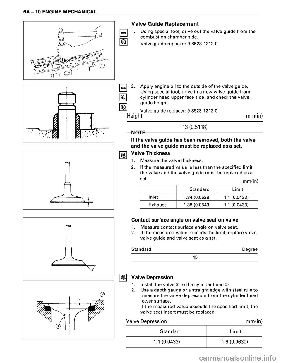
Valve Guide Replacement
1. Using special tool, drive out the valve guide from the
combustion chamber side.
Valve guide replacer: 9-8523-1212-0
2. Apply engine oil to the outside of the valve guide.
Using special tool, drive in a new valve guide from
cylinder head upper face side, and check the valve
guide height.
Valve guide replacer: 9-8523-1212-0
NOTE:
If the valve guide has been removed, both the valve
and the valve guide must be replaced as a set.
Valve Thickness
1. Measure the valve thickness.
2. If the measured value is less than the specified limit,
the valve and the valve guide must be replaced as a
set.
Contact surface angle on valve seat on valve
1. Measure contact surface angle on valve seat.
2. If the measured value exceeds the limit, replace valve,
valve guide and valve seat as a set.
mm(in)
13 (0.5118) Height
Standard
mm(in)
Limit
1.1 (0.0433)
1.6 (0.0630)
Valve Depression
Degree
45 Standard
Valve Depression
1. Install the valve À to the cylinder head Á.
2. Use a depth gauge or a straight edge with steel rule to
measure the valve depression from the cylinder head
lower surface.
If the measured value exceeds the specified limit, the
valve seat insert must be replaced.
Inletmm(in)1.1 (0.0433) Standard Limit
Exhaust1.34 (0.0528)
1.1 (0.0433) 1.38 (0.0543)
Page 1561 of 3573
ENGINE MECHANICAL 6A Ð 11
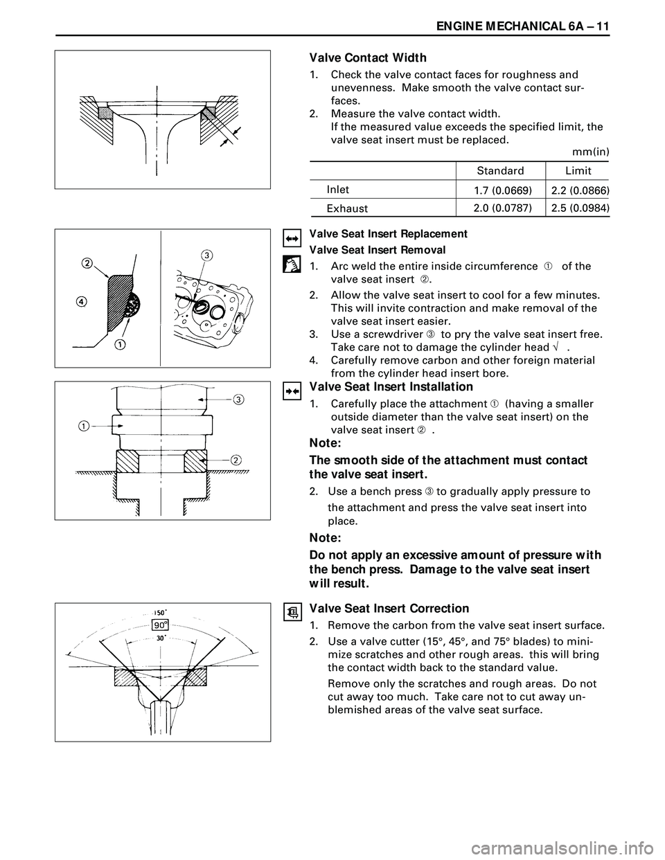
Valve Contact Width
1. Check the valve contact faces for roughness and
unevenness. Make smooth the valve contact sur-
faces.
2. Measure the valve contact width.
If the measured value exceeds the specified limit, the
valve seat insert must be replaced.
Valve Seat Insert Replacement
Valve Seat Insert Removal
1. Arc weld the entire inside circumference À of the
valve seat insert Á.
2. Allow the valve seat insert to cool for a few minutes.
This will invite contraction and make removal of the
valve seat insert easier.
3. Use a screwdriver  to pry the valve seat insert free.
Take care not to damage the cylinder head Ö .
4. Carefully remove carbon and other foreign material
from the cylinder head insert bore.
Valve Seat Insert Installation
1. Carefully place the attachment À (having a smaller
outside diameter than the valve seat insert) on the
valve seat insert Á .
Note:
The smooth side of the attachment must contact
the valve seat insert.
2. Use a bench press  to gradually apply pressure to
the attachment and press the valve seat insert into
place.
Note:
Do not apply an excessive amount of pressure with
the bench press. Damage to the valve seat insert
will result.
Valve Seat Insert Correction
1. Remove the carbon from the valve seat insert surface.
2. Use a valve cutter (15°, 45°, and 75° blades) to mini-
mize scratches and other rough areas. this will bring
the contact width back to the standard value.
Remove only the scratches and rough areas. Do not
cut away too much. Take care not to cut away un-
blemished areas of the valve seat surface.
Inlet
mm(in)
2.2 (0.0866)
Standard Limit
Exhaust1.7 (0.0669)
2.5 (0.0984) 2.0 (0.0787)
Page 1562 of 3573
6A Ð 12 ENGINE MECHANICAL
3. Visually inspect both ends of the push rod for exces-
sive wear and damage. The push rod must be re-
placed if these conditions are discovered during
inspection.
REASSEMBLY
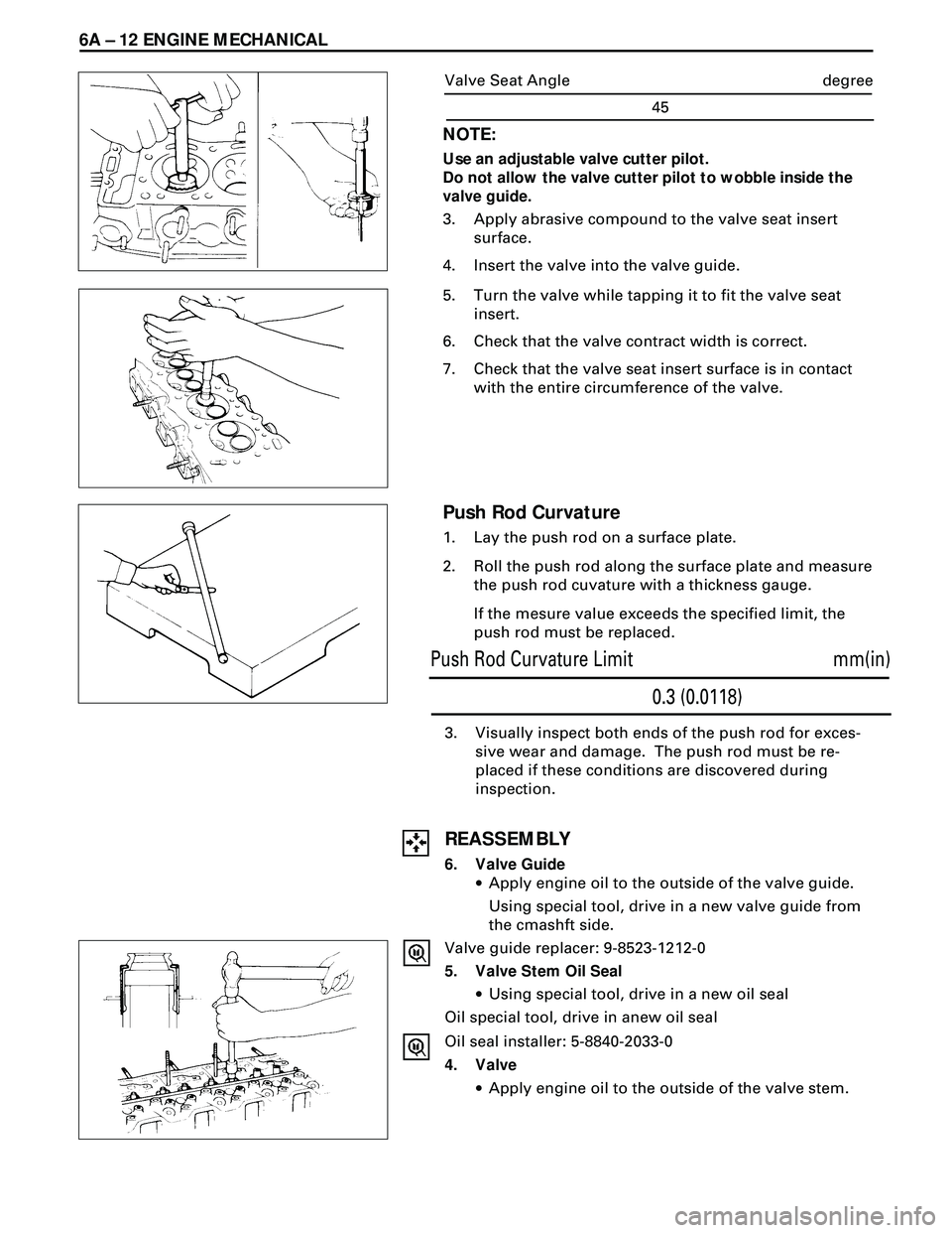
6. Valve Guide
·Apply engine oil to the outside of the valve guide.
Using special tool, drive in a new valve guide from
the cmashft side.
Valve guide replacer: 9-8523-1212-0
5. Valve Stem Oil Seal
·Using special tool, drive in a new oil seal
Oil special tool, drive in anew oil seal
Oil seal installer: 5-8840-2033-0
4. Valve
·Apply engine oil to the outside of the valve stem.
Push Rod Curvature
1. Lay the push rod on a surface plate.
2. Roll the push rod along the surface plate and measure
the push rod cuvature with a thickness gauge.
If the mesure value exceeds the specified limit, the
push rod must be replaced.
NOTE:
Use an adjustable valve cutter pilot.
Do not allow the valve cutter pilot to wobble inside the
valve guide.
3. Apply abrasive compound to the valve seat insert
surface.
4. Insert the valve into the valve guide.
5. Turn the valve while tapping it to fit the valve seat
insert.
6. Check that the valve contract width is correct.
7. Check that the valve seat insert surface is in contact
with the entire circumference of the valve.
mm(in)
0.3 (0.0118) Push Rod Curvature Limit
degree
45 Valve Seat Angle
Page 1570 of 3573
6A Ð 20 ENGINE MECHANICAL
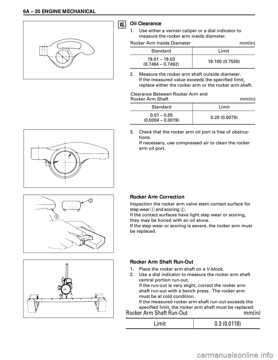
Oil Clearance
1. Use either a vernier caliper or a dial indicator to
measure the rocker arm inside diameter.
2. Measure the rocker arm shaft outside diameter.
If the measured value exceeds the specified limit,
replace either the rocker arm or the rocker arm shaft.
3. Check that the rocker arm oil port is free of obstruc-
tions.
If necessary, use compressed air to clean the rocker
arm oil port.
Rocker Arm Correction
Inspection the rocker arm valve stem contact surface for
step wear 1 and scoring 2.
If the contact surfaces have light step wear or scoring,
they may be honed with an oil stone.
If the step wear or scoring is severe, the rocker arm must
be replaced.
Rocker Arm Shaft Run-Out
1. Place the rocker arm shaft on a V-block.
2. Use a dial indicator to measure the rocker arm shaft
central portion run-out.
If the run-out is very slight, correct the rocker arm
shaft run-out with a bench press. The rocker arm
must be at cold condition.
If the measured rocker arm shaft run-out exceeds the
specified limit, the rocker arm shaft must be replaced.
0.3 (0.0118)
mm(in) Rocker Arm Shaft Run-Out
Limit
Standard Limit
mm(in)
19.01 – 19.03
(0.7484 – 0.7492)19.100 (0.7520) Rocker Arm Inside Diameter
Standard Limit
mm(in)
0.01 – 0.05
(0.0004 – 0.0019)0.20 (0.0079) Clearance Between Rocker Arm and
Rocker Arm Shaft