sensor ISUZU TROOPER 1998 Service Workshop Manual
[x] Cancel search | Manufacturer: ISUZU, Model Year: 1998, Model line: TROOPER, Model: ISUZU TROOPER 1998Pages: 3573, PDF Size: 60.36 MB
Page 399 of 3573
FRONT SUSPENSION 3C – 11
REMOVAL
Preparation:
1) Raise the vehicle and support the frame with suitable
safety stands.
2) Remove wheel and tire assembly. Refer to “Wheels
and Tires” in section 3E.
3) Remove the brake caliper. Refer to “Brakes” in section
5.
4) Remove the hub assembly. Refer to “Hub and Disk” in
section 4C.
5) Remove outer track rod from the knuckle. Refer to
“Steering Linkage” in section 2A.
1. Torsion Bar
Loosen torsion bar by height control arm adjust bolt.
Refer to “Torsion bar” in this section.
2. Wheel speed sensor (if equipped with ABS)
3. Back Plate
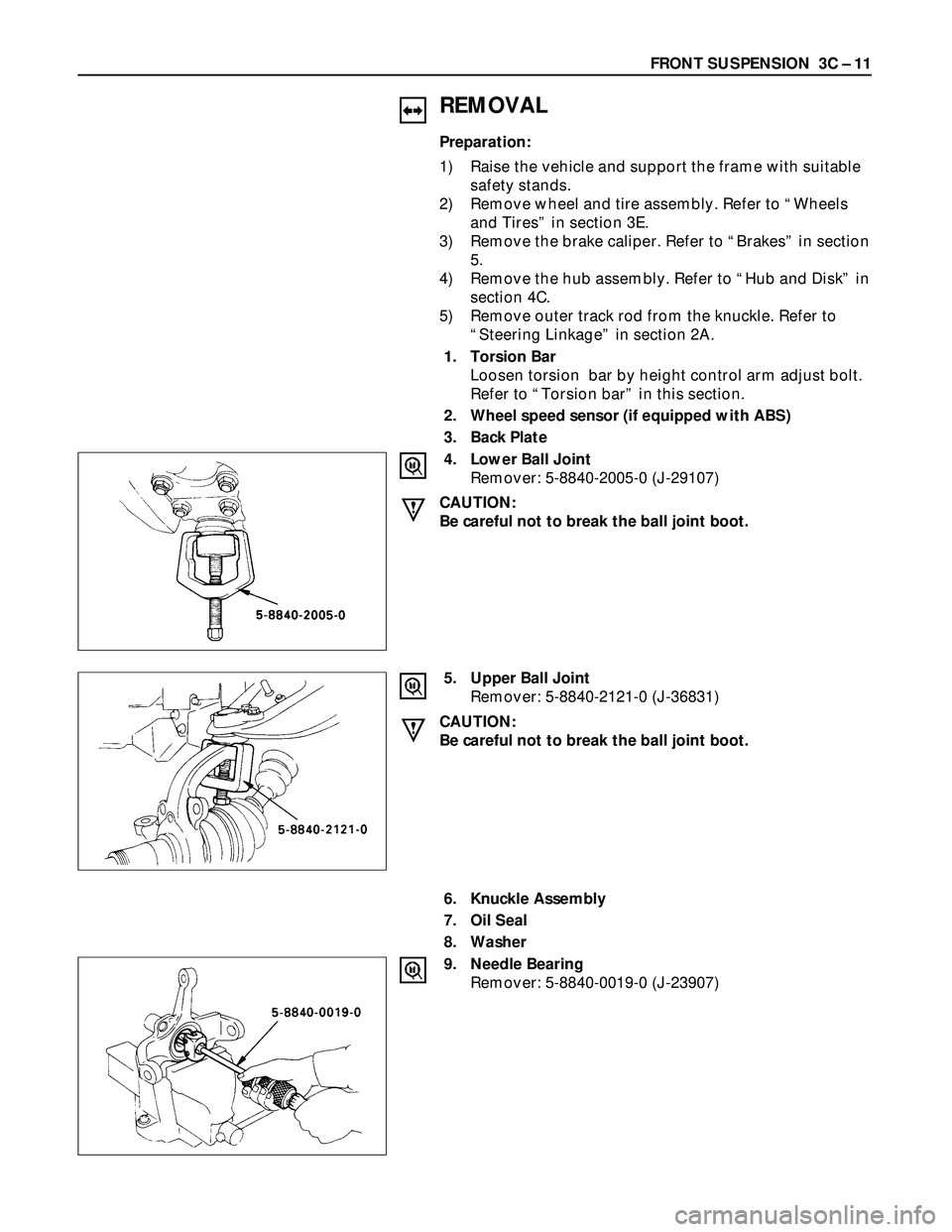
4. Lower Ball Joint
Remover: 5-8840-2005-0 (J-29107)
CAUTION:
Be careful not to break the ball joint boot.
5. Upper Ball Joint
Remover: 5-8840-2121-0 (J-36831)
CAUTION:
Be careful not to break the ball joint boot.
6. Knuckle Assembly
7. Oil Seal
8. Washer
9. Needle Bearing
Remover: 5-8840-0019-0 (J-23907)
Page 401 of 3573
FRONT SUSPENSION 3C – 13
4. Lower Ball Joint
Tighten the nut to the specified torque, with just
enough additional torque to align cotter pin holes.
Install new cotter pin.
Lower Ball Joint Nut Torque N·m (kg·m/lb·ft)
147 (15.0 / 108)
3. Back Plate
2. Wheel Speed Sensor (if equipped with ABS)
Tighten the bolt to the specified torque.
Wheel Speed Sensor Bolt Torque N·m (kg·m/lb·in)
8 (0.8 / 69)
1. Torsion Bar
Refer to “Torsion Bar” in this section.
NOTE:
Adjust the trim height. Refer to “Front End
Alignment” in section 2A.
Page 402 of 3573

3C – 14 FRONT SUSPENSION
UPPER CONTROL ARM
Removal Steps
1. Speed sensor cable (if equipped with
ABS)
2. Nut and cotter pin
3. Upper ball joint
4. Bolt and plate
5. Nut assembly
6. Camber shims
7. Caster shims
8. Upper control arm assembly
9. Nut
10. Plate
11. Bushing
12. Fulcrum pin
Installation Steps
12. Fulcrum pin
11. Bushing
10. Plate
9. Nut
8. Upper control arm assembly
7. Caster shims
6. Camber shims
5. Nut assembly
4. Bolt and plate
3. Upper ball joint
2. Nut and cotter pin
1. Speed sensor cable (if equipped with
ABS)
Page 403 of 3573
FRONT SUSPENSION 3C – 15
REMOVAL
Preparation:
1) Raise the vehicle and support the frame with suitable
safety stands.
2) Remove wheel and tire assembly. Refer to “Wheels
and Tires” in section 3E.
3) Remove the brake caliper and disconnect flexible hose.
Refer to “Brakes” in section 5.
4) Support lower control arm with a jack.
1. Speed Sensor Cable (if equipped with ABS)
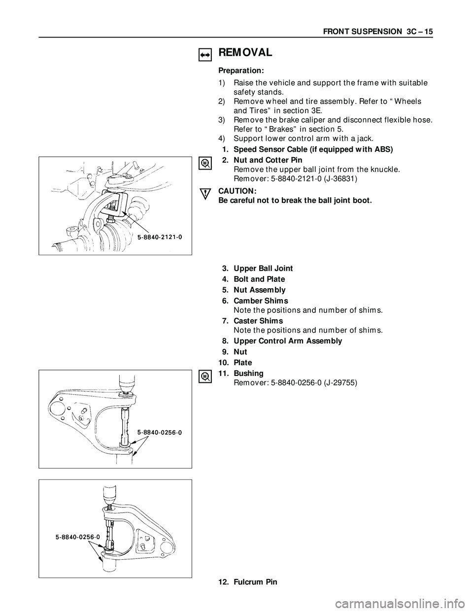
2. Nut and Cotter Pin
Remove the upper ball joint from the knuckle.
Remover: 5-8840-2121-0 (J-36831)
CAUTION:
Be careful not to break the ball joint boot.
3. Upper Ball Joint
4. Bolt and Plate
5. Nut Assembly
6. Camber Shims
Note the positions and number of shims.
7. Caster Shims
Note the positions and number of shims.
8. Upper Control Arm Assembly
9. Nut
10. Plate
11. Bushing
Remover: 5-8840-0256-0 (J-29755)
12. Fulcrum Pin
Page 405 of 3573

FRONT SUSPENSION 3C – 17
8. Upper Control Arm Assembly
Install upper control arm assembly with the fulcrum
pin projections turned inward.
7. Caster Shims
Install the caster shims between the chassis frame and
fulcrum pin.
6. Camber Shims
Install the camber shims between the chassis frame
and fulcrum pin.
5. Nut Assembly
4. Bolt and Plate
Fulcrum Pin Bolt Torque N·m (kg·m/lb·ft)
152 (15.2 / 112)
3. Upper Ball Joint
Upper Ball Joint Nut Torque N·m (kg·m/lb·ft)
57 (5.8 / 42)
2. Nut and Cotter Pin
Tighten the nut to the specified torque, with just
enough additional torque to align cotter pin holes.
Install new cotter pin.
Upper Ball Joint Nut Torque N·m (kg·m/lb·ft)
98 (10.0 / 72)
1. Speed Sensor Cable (if equipped with ABS)
Page 410 of 3573

3C – 22 FRONT SUSPENSION
UPPER BALL JOINT
Removal Steps
1. Nut and cotter pin
2. Bolt, nut and washer
3. Upper ball joint
Installation Steps
3. Upper ball joint
2. Bolt, nut and washer
1. Nut and cotter pin
REMOVAL
Preparation:
1) Raise the vehicle and support the frame with suitable
safety stands.
2) Remove the speed sensor from the knuckle (If
equipped with ABS).
Page 425 of 3573

3D – 10 REAR SUSPENSION; COIL SPRING
CENTER LINK
3
34
1
2
Removal Steps
1. Speed sensor cable
(If equipped with ABS)
2. Speed sensor cable bracket
(If equipped with ABS)
3. Bolt and nut
4. Center link
Installation Steps
4. Center link
3. Bolt and nut
2. Speed sensor cable bracket
(If equipped with ABS)
1. Speed sensor cable
(If equipped with ABS)
REMOVAL
1. Speed Sensor Cable (If equipped with ABS)
Remove the speed sensor cable from the center link.
2. Speed Sensor Cable Bracket (If equipped with ABS)
Remove the speed sensor cable bracket from the
frame.
3. Bolt and Nut
4. Center Link
460RW026
Page 426 of 3573
REAR SUSPENSION; COIL SPRING 3D – 11
INSPECTION AND REPAIR
Make necessary correction or parts replacement if wear,
damage, corrosion or any other abnormal condition are
found through inspection.
1. Center Link
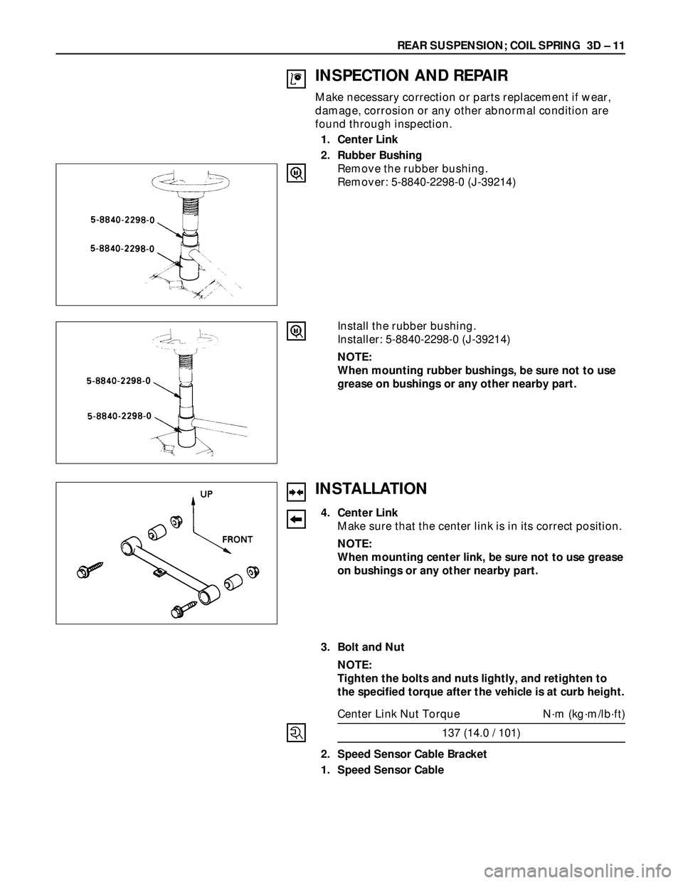
2. Rubber Bushing
Remove the rubber bushing.
Remover: 5-8840-2298-0 (J-39214)
Install the rubber bushing.
Installer: 5-8840-2298-0 (J-39214)
NOTE:
When mounting rubber bushings, be sure not to use
grease on bushings or any other nearby part.
INSTALLATION
4. Center Link
Make sure that the center link is in its correct position.
NOTE:
When mounting center link, be sure not to use grease
on bushings or any other nearby part.
3. Bolt and Nut
NOTE:
Tighten the bolts and nuts lightly, and retighten to
the specified torque after the vehicle is at curb height.
Center Link Nut Torque N·m (kg·m/lb·ft)
137 (14.0 / 101)
2. Speed Sensor Cable Bracket
1. Speed Sensor Cable
Page 443 of 3573
DIFFERENTIAL (FRONT) 4A1±6
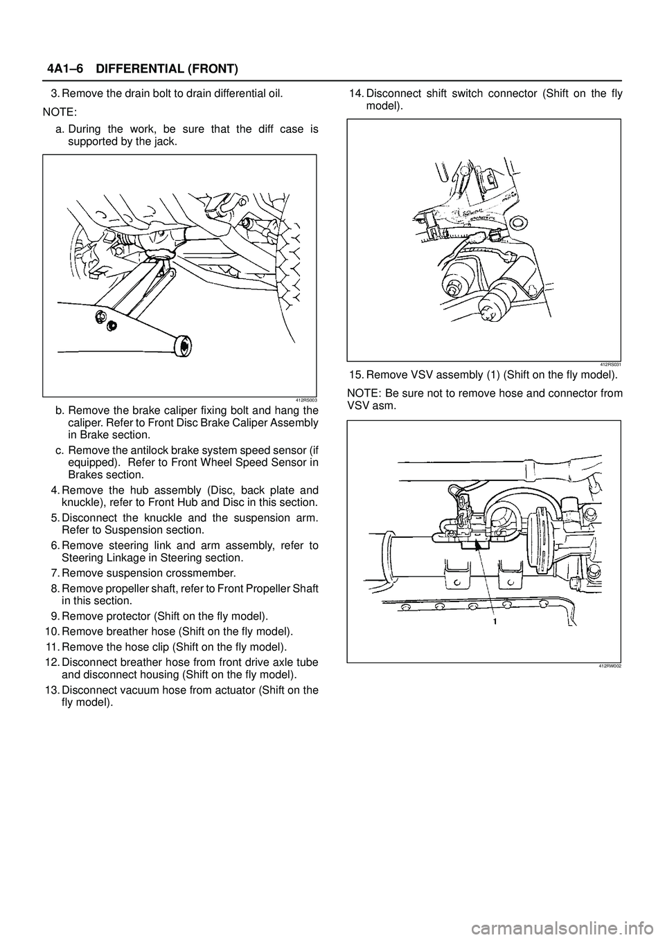
3. Remove the drain bolt to drain differential oil.
NOTE:
a. During the work, be sure that the diff case is
supported by the jack.
412RS003
b. Remove the brake caliper fixing bolt and hang the
caliper. Refer to Front Disc Brake Caliper Assembly
in Brake section.
c. Remove the antilock brake system speed sensor (if
equipped). Refer to Front Wheel Speed Sensor in
Brakes section.
4. Remove the hub assembly (Disc, back plate and
knuckle), refer to Front Hub and Disc in this section.
5. Disconnect the knuckle and the suspension arm.
Refer to Suspension section.
6. Remove steering link and arm assembly, refer to
Steering Linkage in Steering section.
7. Remove suspension crossmember.
8. Remove propeller shaft, refer to Front Propeller Shaft
in this section.
9. Remove protector (Shift on the fly model).
10. Remove breather hose (Shift on the fly model).
11. Remove the hose clip (Shift on the fly model).
12. Disconnect breather hose from front drive axle tube
and disconnect housing (Shift on the fly model).
13. Disconnect vacuum hose from actuator (Shift on the
fly model).14. Disconnect shift switch connector (Shift on the fly
model).
412RS031
15. Remove VSV assembly (1) (Shift on the fly model).
NOTE: Be sure not to remove hose and connector from
VSV asm.
412RW002
Page 471 of 3573
4A2A±4
DIFFERENTIAL (REAR 220mm)
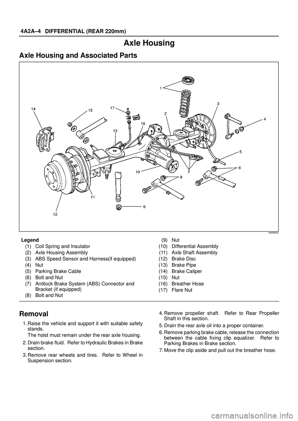
Axle Housing
Axle Housing and Associated Parts
420RW022
Legend
(1) Coil Spring and Insulator
(2) Axle Housing Assembly
(3) ABS Speed Sensor and Harness(if equipped)
(4) Nut
(5) Parking Brake Cable
(6) Bolt and Nut
(7) Antilock Brake System (ABS) Connector and
Bracket (if equipped)
(8) Bolt and Nut(9) Nut
(10) Differential Assembly
(11) Axle Shaft Assembly
(12) Brake Disc
(13) Brake Pipe
(14) Brake Caliper
(15) Nut
(16) Breather Hose
(17) Flare Nut
Removal
1. Raise the vehicle and support it with suitable safety
stands.
The hoist must remain under the rear axle housing.
2. Drain brake fluid. Refer to Hydraulic Brakes in Brake
section.
3. Remove rear wheels and tires. Refer to Wheel in
Suspension section.4. Remove propeller shaft. Refer to Rear Propeller
Shaft in this section.
5. Drain the rear axle oil into a proper container.
6. Remove parking brake cable, release the connection
between the cable fixing clip equalizer. Refer to
Parking Brakes in Brake section.
7. Move the clip aside and pull out the breather hose.