fuel pump ISUZU TROOPER 1998 Service Manual PDF
[x] Cancel search | Manufacturer: ISUZU, Model Year: 1998, Model line: TROOPER, Model: ISUZU TROOPER 1998Pages: 3573, PDF Size: 60.36 MB
Page 1651 of 3573
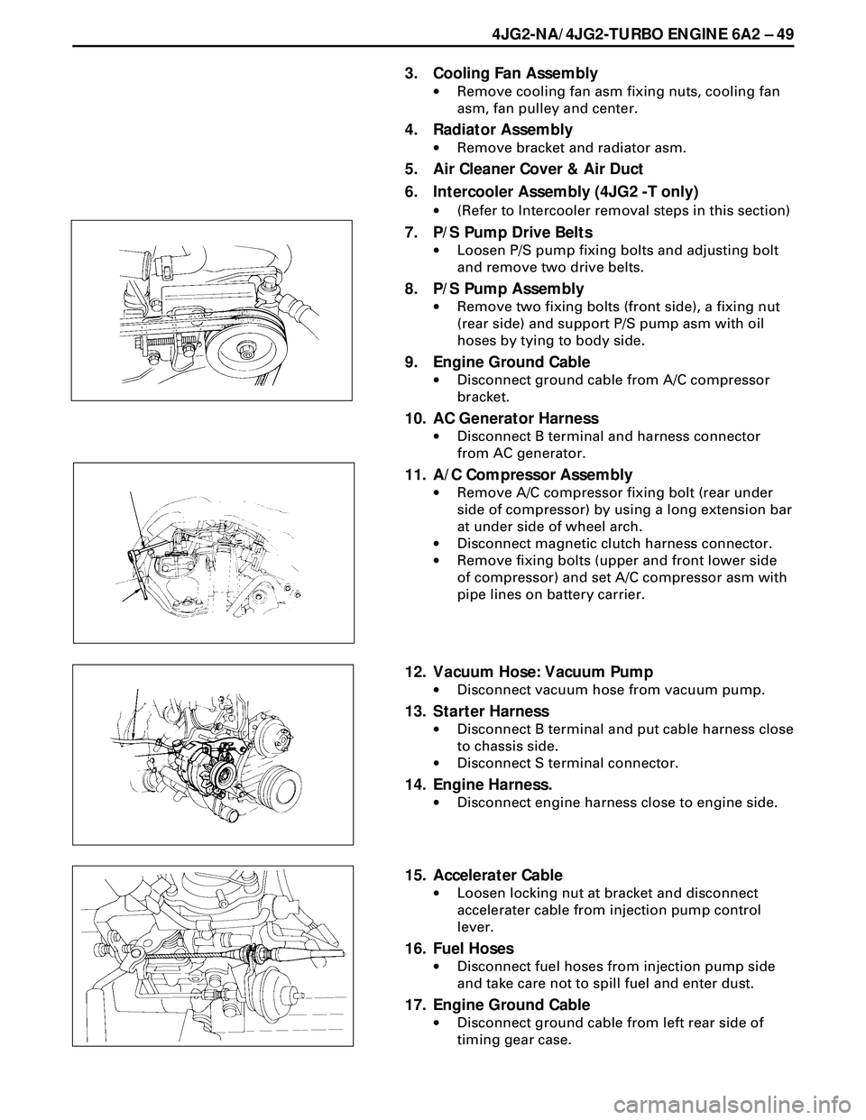
4JG2-NA/4JG2-TURBO ENGINE 6A2 Ð 49
3. Cooling Fan Assembly
·Remove cooling fan asm fixing nuts, cooling fan
asm, fan pulley and center.
4. Radiator Assembly
·Remove bracket and radiator asm.
5. Air Cleaner Cover & Air Duct
6. Intercooler Assembly (4JG2 -T only)
·(Refer to Intercooler removal steps in this section)
7. P/S Pump Drive Belts
·Loosen P/S pump fixing bolts and adjusting bolt
and remove two drive belts.
8. P/S Pump Assembly
·Remove two fixing bolts (front side), a fixing nut
(rear side) and support P/S pump asm with oil
hoses by tying to body side.
9. Engine Ground Cable
·Disconnect ground cable from A/C compressor
bracket.
10. AC Generator Harness
·Disconnect B terminal and harness connector
from AC generator.
11. A/C Compressor Assembly
·Remove A/C compressor fixing bolt (rear under
side of compressor) by using a long extension bar
at under side of wheel arch.
·Disconnect magnetic clutch harness connector.
·Remove fixing bolts (upper and front lower side
of compressor) and set A/C compressor asm with
pipe lines on battery carrier.
12. Vacuum Hose: Vacuum Pump
·Disconnect vacuum hose from vacuum pump.
13. Starter Harness
·Disconnect B terminal and put cable harness close
to chassis side.
·Disconnect S terminal connector.
14. Engine Harness.
·Disconnect engine harness close to engine side.
15. Accelerater Cable
·Loosen locking nut at bracket and disconnect
accelerater cable from injection pump control
lever.
16. Fuel Hoses
·Disconnect fuel hoses from injection pump side
and take care not to spill fuel and enter dust.
17. Engine Ground Cable
·Disconnect ground cable from left rear side of
timing gear case.
Page 1652 of 3573
6A2 Ð 50 4JG2-NA/4JG2-TURBO ENGINE
18. Vacuum Hose : Vacuum Tank
·Disconnect vacuum hose from vacuum pump
side.
19. Glow Plug Harness
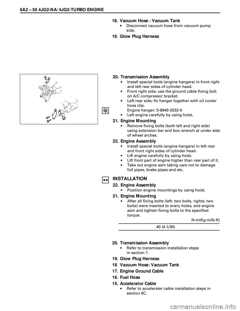
20. Transmission Assembly
·Install special tools (engine hangers) in front right
and left rear sides of cylinder head.
·Front right side; use the ground cable fixing bolt
on A/C compressor bracket.
·Left rear side; fix hanger together with oil cooler
hose clip.
Engine hanger: 5-8840-2032-0
·Left engine carefully by using hoist.
21. Engine Mounting
·Remove fixing bolts (both left and right side)
using extension bar and box wrench at under side
of wheel arches.
22. Engine Assembly
·Install special tools (engine hangers) in left rear
and front right sides of cylinder head.
·Lift engine carefully by using hoist.
·Lift front part of engine higher than rear part of it.
·Take out engine asm taking care not to damage
full pipes, brake pipes and etc.
INSTALLATION
22. Engine Assembly
·Position engine mountings by using hoist.
21. Engine Mounting
·After all fixing bolts (left: two bolts, rights: two
bolts) were inserted to every holes, and engine
asm and tighten fixing bolts to the specified
torque.
40 (4.1/30)N·m(Kg·m/lb·ft)
20. Transmission Assembly
·Refer to transmission installation steps
in section 7.
19. Glow Plug Harness
18 Vacuum Hose: Vacuum Tank
17. Engine Ground Cable
16. Fuel Hose
15. Accelerator Cable
·Refer to accelerater cable installation steps in
section 6C.
Page 1667 of 3573
FUEL SYSTEM 6C Ð 1
PAGE
General Description ....................................................................................................................... 6C- 1
On-Vehicle Service ......................................................................................................................... 6C- 7
Fuel Filter Assembly .................................................................................................................. 6C- 7
Fuel Filter Cartrige ..................................................................................................................... 6C- 8
Injection nozzle .......................................................................................................................... 6C- 9
Injection Pump Assembly ......................................................................................................... 6C-14
Fuel Tank .................................................................................................................................... 6C-18
Fuel Gauge Unit ......................................................................................................................... 6C-19
Fuel Filler Cap ............................................................................................................................ 6C-20
Accelerator Control ........................................................................................................................ 6C-21
Accelerator Control Cable ........................................................................................................ 6C-21
Accelerator Pedal ...................................................................................................................... 6C-23
Air Cleaner .................................................................................................................................. 6C-24
SECTION 6C
FUEL SYSTEM
CONTENTS
GENERAL DESCRIPTION
When working on the fuel system, there are several
things to keep in mind:
·Any time the fuel system is being worked on,
disconnect the negative battery cable except for
those tests where battery voltage is required.
·Always keep a dry chemical (Class B) fire extin-
guisher near the work area.
·Replace all pipes with the same pipe and fittings
that were removed.
Clean and inspect ÒOÓ rings. Replace where
required.
·Always relieve the line pressure before servicing
any fuel system components.·Do not attempt repairs on the fuel system until
you have read the instructions and checked the
pictures relating to that repair.
Page 1668 of 3573
6C Ð 2 FUEL SYSTEM
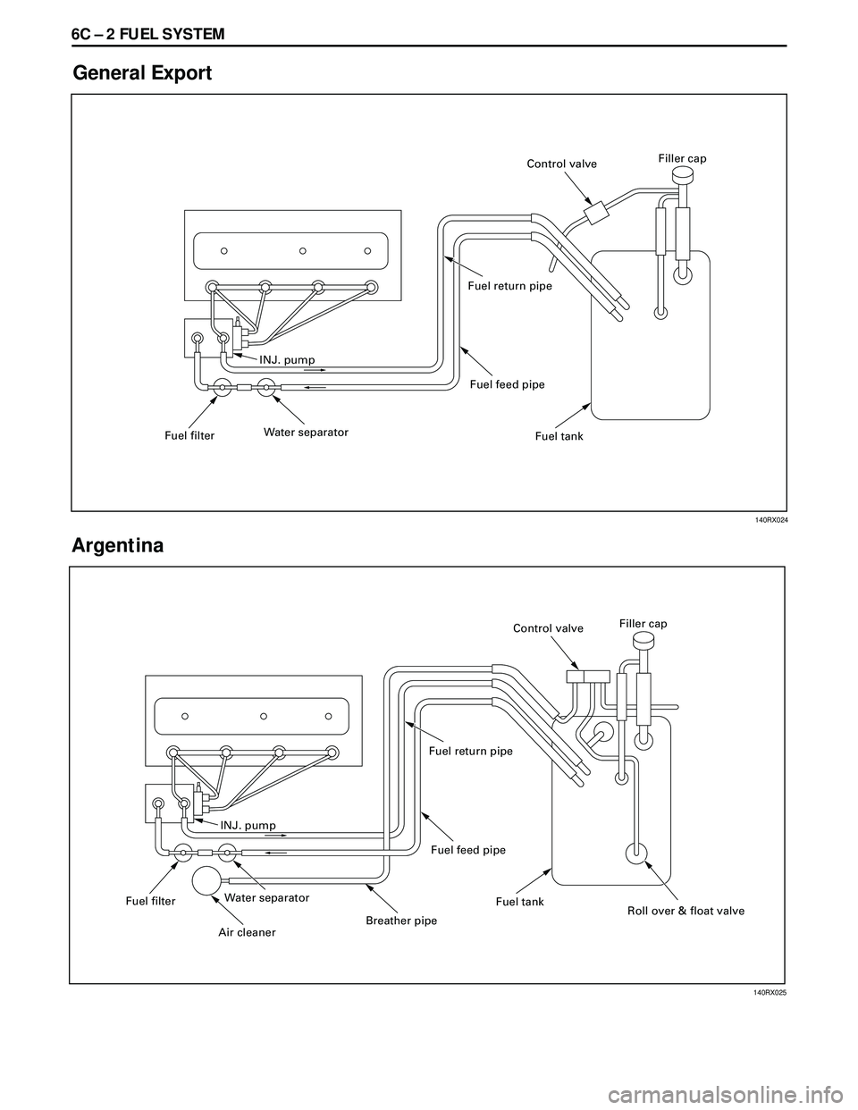
General Export
Argentina
INJ. pump
Fuel filterWater separatorFuel feed pipe Fuel return pipe
Fuel tankFiller cap
Control valve
INJ. pump
Fuel filterWater separator
Air cleaner
Breather pipeFuel feed pipe Fuel return pipe
Fuel tank
Roll over & float valve Filler cap
Control valve
140RX024
140RX025
Page 1670 of 3573
6C Ð 4 FUEL SYSTEM
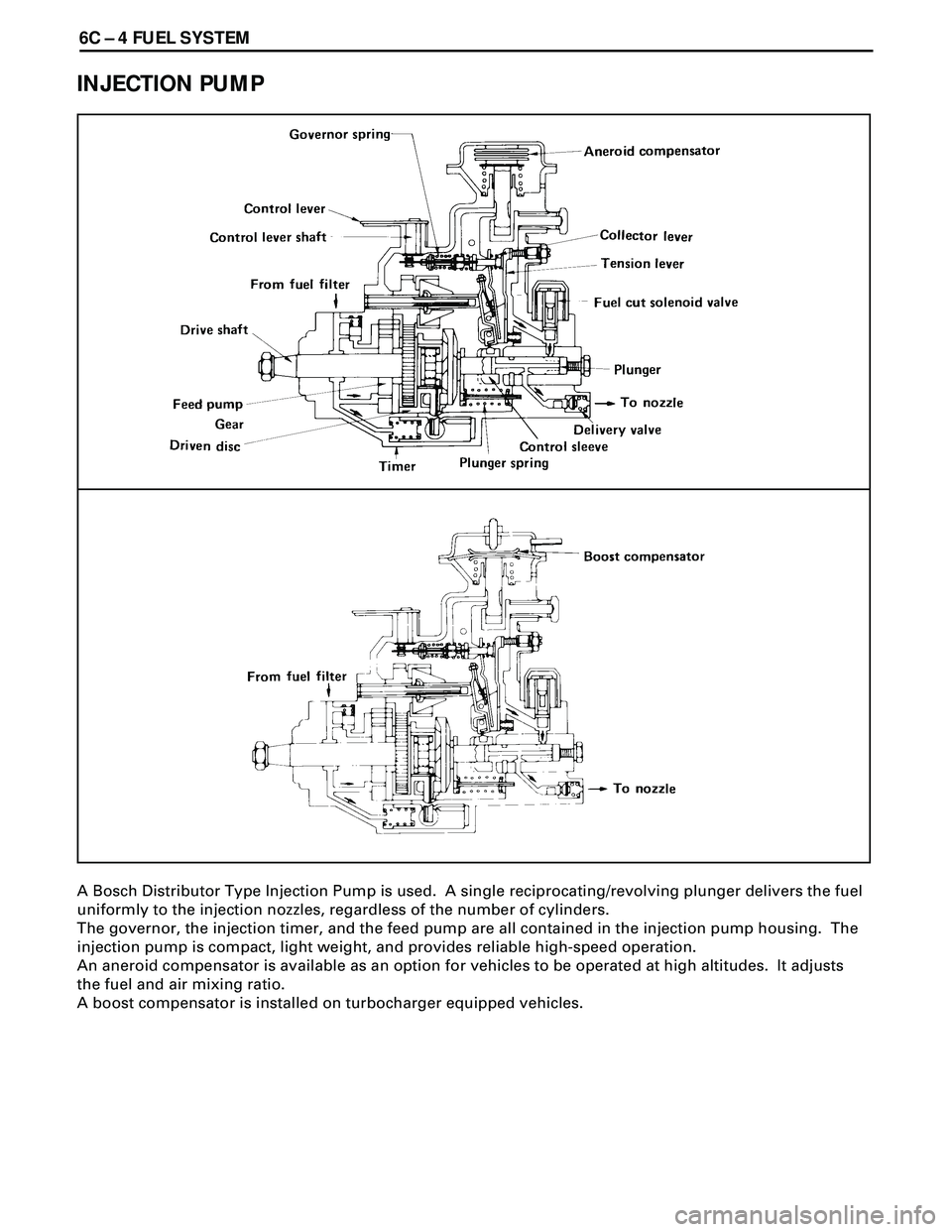
INJECTION PUMP
A Bosch Distributor Type Injection Pump is used. A single reciprocating/revolving plunger delivers the fuel
uniformly to the injection nozzles, regardless of the number of cylinders.
The governor, the injection timer, and the feed pump are all contained in the injection pump housing. The
injection pump is compact, light weight, and provides reliable high-speed operation.
An aneroid compensator is available as an option for vehicles to be operated at high altitudes. It adjusts
the fuel and air mixing ratio.
A boost compensator is installed on turbocharger equipped vehicles.
Page 1671 of 3573
FUEL SYSTEM 6C Ð 5
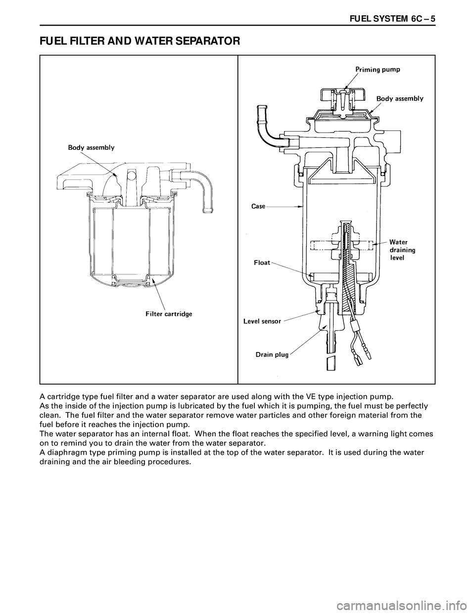
FUEL FILTER AND WATER SEPARATOR
A cartridge type fuel filter and a water separator are used along with the VE type injection pump.
As the inside of the injection pump is lubricated by the fuel which it is pumping, the fuel must be perfectly
clean. The fuel filter and the water separator remove water particles and other foreign material from the
fuel before it reaches the injection pump.
The water separator has an internal float. When the float reaches the specified level, a warning light comes
on to remind you to drain the water from the water separator.
A diaphragm type priming pump is installed at the top of the water separator. It is used during the water
draining and the air bleeding procedures.
Page 1672 of 3573
6C Ð 6 FUEL SYSTEM
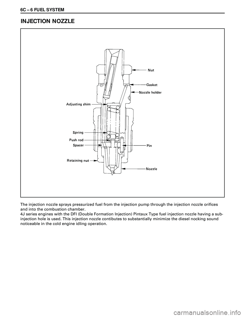
INJECTION NOZZLE
The injection nozzle sprays pressurized fuel from the injection pump through the injection nozzle orifices
and into the combustion chamber.
4J series engines with the DFI (Double Formation Injection) Pintaux Type fuel injection nozzle having a sub-
injection hole is used. This injection nozzle contibutes to substantially minimize the diesel nocking sound
noticeable in the cold engine idling operation.
Page 1673 of 3573
FUEL SYSTEM 6C Ð 7
ON-VEHICLE SERVICE
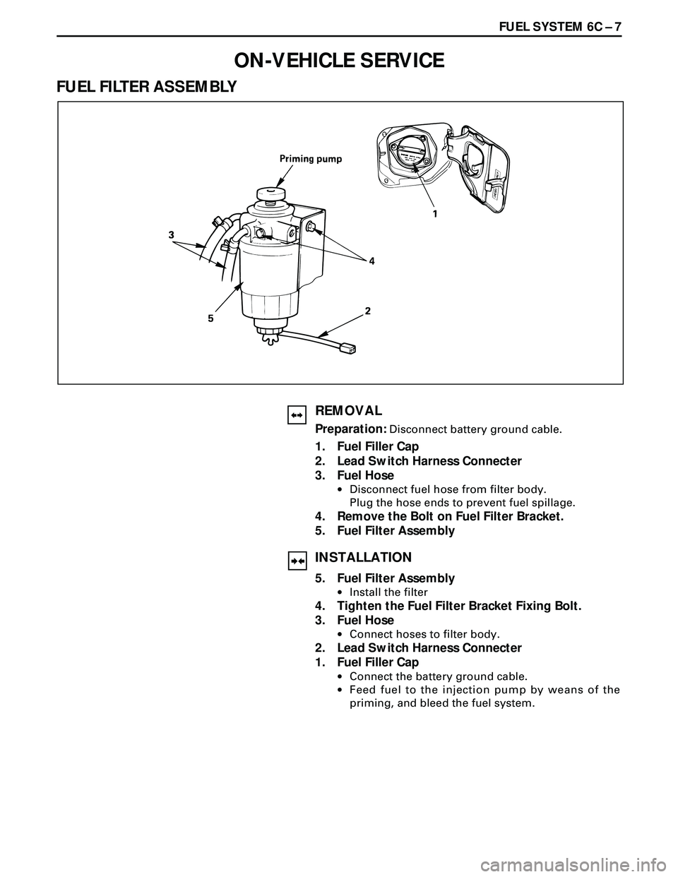
FUEL FILTER ASSEMBLY
REMOVAL
Preparation: Disconnect battery ground cable.
1. Fuel Filler Cap
2. Lead Switch Harness Connecter
3. Fuel Hose
·Disconnect fuel hose from filter body.
Plug the hose ends to prevent fuel spillage.
4. Remove the Bolt on Fuel Filter Bracket.
5. Fuel Filter Assembly
INSTALLATION
5. Fuel Filter Assembly
·Install the filter
4. Tighten the Fuel Filter Bracket Fixing Bolt.
3. Fuel Hose
·Connect hoses to filter body.
2. Lead Switch Harness Connecter
1. Fuel Filler Cap
·Connect the battery ground cable.
·Feed fuel to the injection pump by weans of the
priming, and bleed the fuel system.
Page 1674 of 3573
6C Ð 8 FUEL SYSTEM
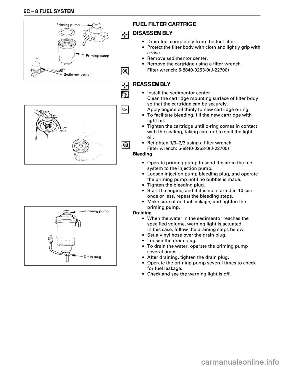
FUEL FILTER CARTRIGE
DISASSEMBLY
·Drain fuel completely from the fuel filter.
·Protect the filter body with cloth and lightly grip with
a vise.
·Remove sedimentor center.
·Remove the cartridge using a filter wrench.
Filter wrench: 5-8840-0253-0(J-22700)
REASSEMBLY
·Install the sedimentor center.
Clean the cartridge mounting surface of filter body
so that the cartridge can be securely.
Apply engine oil thinly to new cartridge o-ring.
·To facilitate bleeding, fill the new cartridge with
light oil.
·Tighten the cartridge until o-ring comes in contact
with the sealing, taking care not to spill the light
oil.
·Retighten 1/3~2/3 using a filter wrench.
Filter wrench: 5-8840-0253-0(J-22700)
Bleeding
·Operate priming pump to send the air in the fuel
system to the injection pump.
·Loosen injection pump bleeding plug, and operate
the priming pump until no bubble is made.
·Tighten the bleeding plug.
·Start the engine, and if it is not started in 10 sec-
onds or less, repeat the bleeding steps.
·Make sure of no fuel leakage, and tighten the
priming pump.
Draining
·When the water in the sedimentor reaches the
specified volume, warning light is actuated.
In this case, follow the draining steps below.
·Set a vinyI hose over the drain plug.
·Loosen the drain plug.
·To drain the water, operate the priming pump
several times.
·After draining, tighten the drain plug.
·Operate the priming pump several times to check
for fuel leakage.
·Check and see the warning light is off.
Page 1675 of 3573
FUEL SYSTEM 6C Ð 9
INJECTION NOZZLE
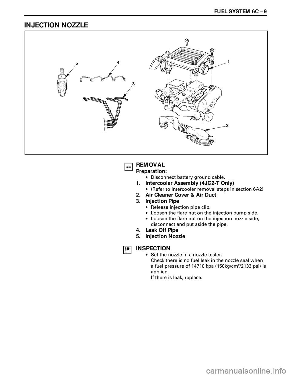
REMOVAL
Preparation:
·Disconnect battery ground cable.
1. Intercooler Assembly (4JG2-T Only)
·(Refer to intercooler removal steps in section 6A2)
2. Air Cleaner Cover & Air Duct
3. Injection Pipe
·Release injection pipe clip.
·Loosen the flare nut on the injection pump side.
·Loosen the flare nut on the injection nozzle side,
disconnect and put aside the pipe.
4. Leak Off Pipe
5. Injection Nozzle
INSPECTION
·Set the nozzle in a nozzle tester.
Check there is no fuel leak in the nozzle seal when
a fuel pressure of 14710 kpa (150kg/cm
2/2133 psi) is
applied.
If there is leak, replace.