relay ISUZU TROOPER 1998 Service Manual PDF
[x] Cancel search | Manufacturer: ISUZU, Model Year: 1998, Model line: TROOPER, Model: ISUZU TROOPER 1998Pages: 3573, PDF Size: 60.36 MB
Page 345 of 3573
STEERING LINKAGE 2A – 43
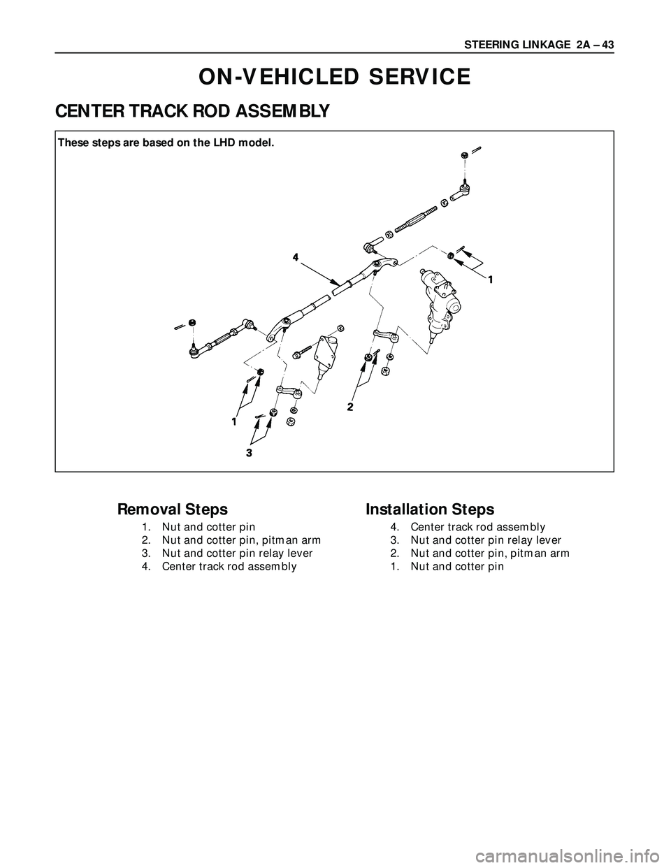
ON-VEHICLED SERVICE
CENTER TRACK ROD ASSEMBLY
Removal Steps
1. Nut and cotter pin
2. Nut and cotter pin, pitman arm
3. Nut and cotter pin relay lever
4. Center track rod assembly
Installation Steps
4. Center track rod assembly
3. Nut and cotter pin relay lever
2. Nut and cotter pin, pitman arm
1. Nut and cotter pin These steps are based on the LHD model.
Page 346 of 3573
2A – 44 STEERING LINKAGE
REMOVAL
Preparation:
Raise the vehicle and support the frame with suitable
safety stands.
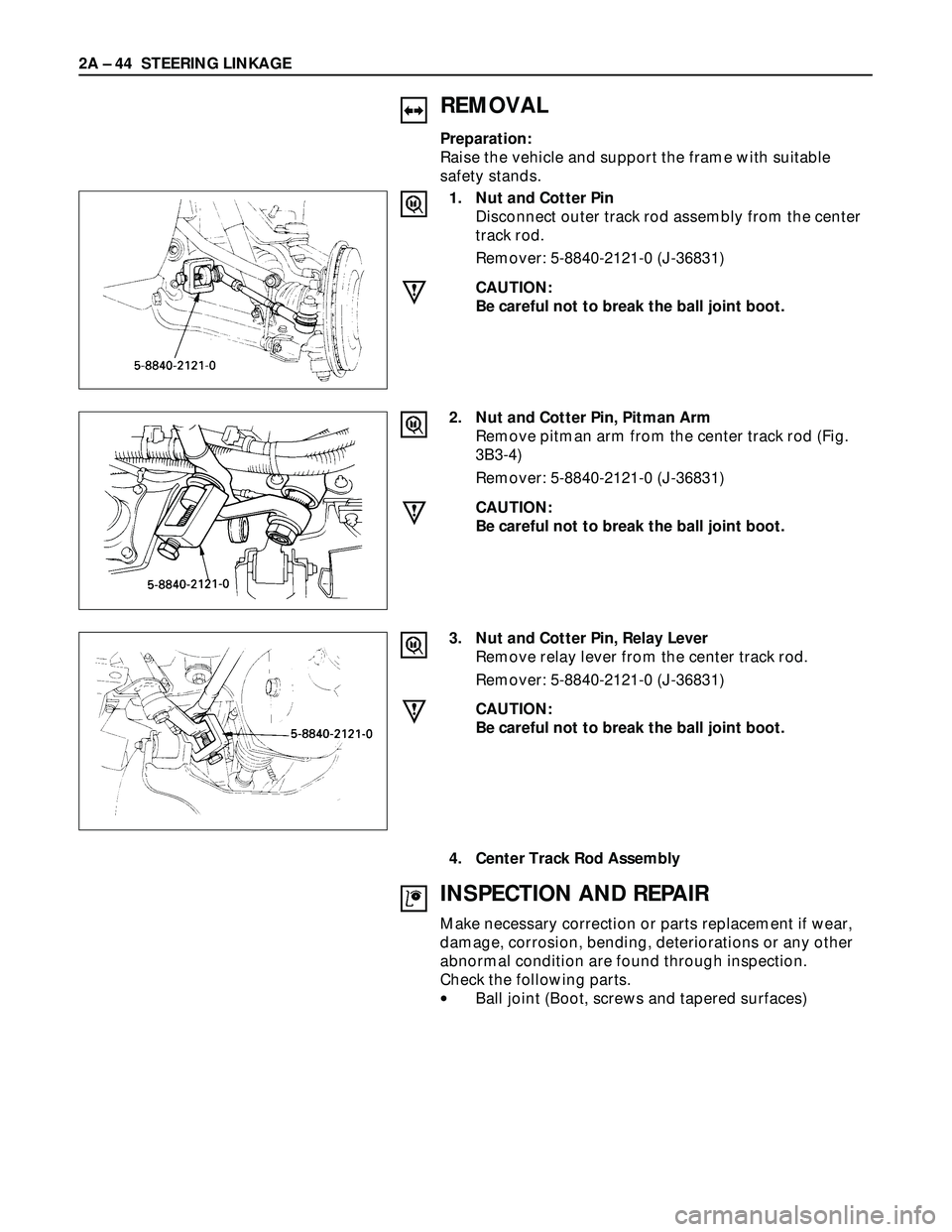
1. Nut and Cotter Pin
Disconnect outer track rod assembly from the center
track rod.
Remover: 5-8840-2121-0 (J-36831)
CAUTION:
Be careful not to break the ball joint boot.
2. Nut and Cotter Pin, Pitman Arm
Remove pitman arm from the center track rod (Fig.
3B3-4)
Remover: 5-8840-2121-0 (J-36831)
CAUTION:
Be careful not to break the ball joint boot.
3. Nut and Cotter Pin, Relay Lever
Remove relay lever from the center track rod.
Remover: 5-8840-2121-0 (J-36831)
CAUTION:
Be careful not to break the ball joint boot.
4. Center Track Rod Assembly
INSPECTION AND REPAIR
Make necessary correction or parts replacement if wear,
damage, corrosion, bending, deteriorations or any other
abnormal condition are found through inspection.
Check the following parts.
•Ball joint (Boot, screws and tapered surfaces)
Page 347 of 3573
STEERING LINKAGE 2A – 45
INSTALLATION
4. Center Track Rod Assembly
3. Nut and Cotter Pin, Relay Lever
Tighten the nut to the specified torque, with just
enough additional torque to align cotter pin holes.
Install new cotter pin.
Relay Lever Nut Torque N·m (kg·m/lb·ft)
59 (6.0 / 43)
2. Nut and Cotter Pin, Pitman Arm
Tighten the nut to the specified torque, with just
enough additional torque to align cotter pin hole.
Install new cotter pin.
Pitman Arm Nut Torque N·m (kg·m/lb·ft)
98 (10.0 / 72)
1. Nut and Cotter Pins
Tighten the nut to the specified torque, with just
enough additional torque to align cotter pin holes.
Install new cotter pin.
Center Track Rod Nut Torque N·m (kg·m/lb·ft)
98 (10.0 / 72)
Page 351 of 3573
STEERING LINKAGE 2A – 49
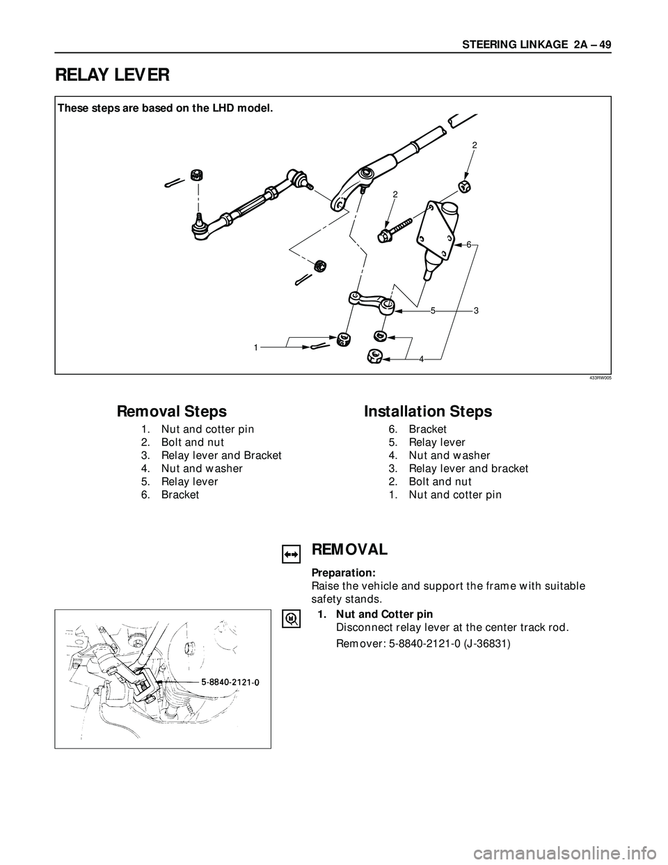
RELAY LEVER
2
2
3
6
5
4 1 hese steps are based on the LHD model.
Removal Steps
1. Nut and cotter pin
2. Bolt and nut
3. Relay lever and Bracket
4. Nut and washer
5. Relay lever
6. Bracket
Installation Steps
6. Bracket
5. Relay lever
4. Nut and washer
3. Relay lever and bracket
2. Bolt and nut
1. Nut and cotter pin
REMOVAL
Preparation:
Raise the vehicle and support the frame with suitable
safety stands.
1. Nut and Cotter pin
Disconnect relay lever at the center track rod.
Remover: 5-8840-2121-0 (J-36831)
433RW005
These steps are based on the LHD model.
Page 352 of 3573
2A – 50 STEERING LINKAGE
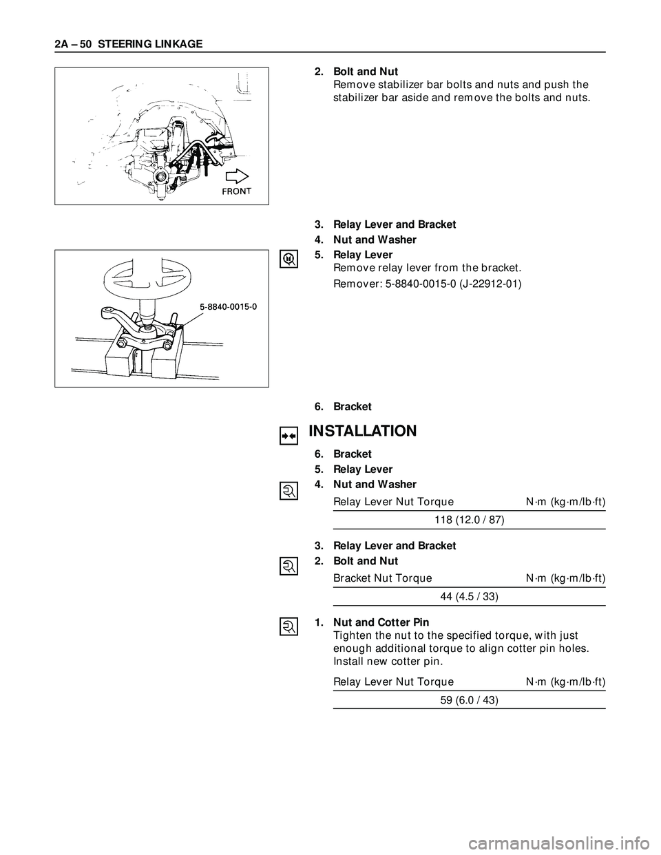
2. Bolt and Nut
Remove stabilizer bar bolts and nuts and push the
stabilizer bar aside and remove the bolts and nuts.
3. Relay Lever and Bracket
4. Nut and Washer
5. Relay Lever
Remove relay lever from the bracket.
Remover: 5-8840-0015-0 (J-22912-01)
6. Bracket
INSTALLATION
6. Bracket
5. Relay Lever
4. Nut and Washer
Relay Lever Nut Torque N·m (kg·m/lb·ft)
118 (12.0 / 87)
3. Relay Lever and Bracket
2. Bolt and Nut
Bracket Nut Torque N·m (kg·m/lb·ft)
44 (4.5 / 33)
1. Nut and Cotter Pin
Tighten the nut to the specified torque, with just
enough additional torque to align cotter pin holes.
Install new cotter pin.
Relay Lever Nut Torque N·m (kg·m/lb·ft)
59 (6.0 / 43)
Page 545 of 3573
4B1±12
DRIVE LINE CONTROL SYSTEM (SHIFT ON THE FLY)
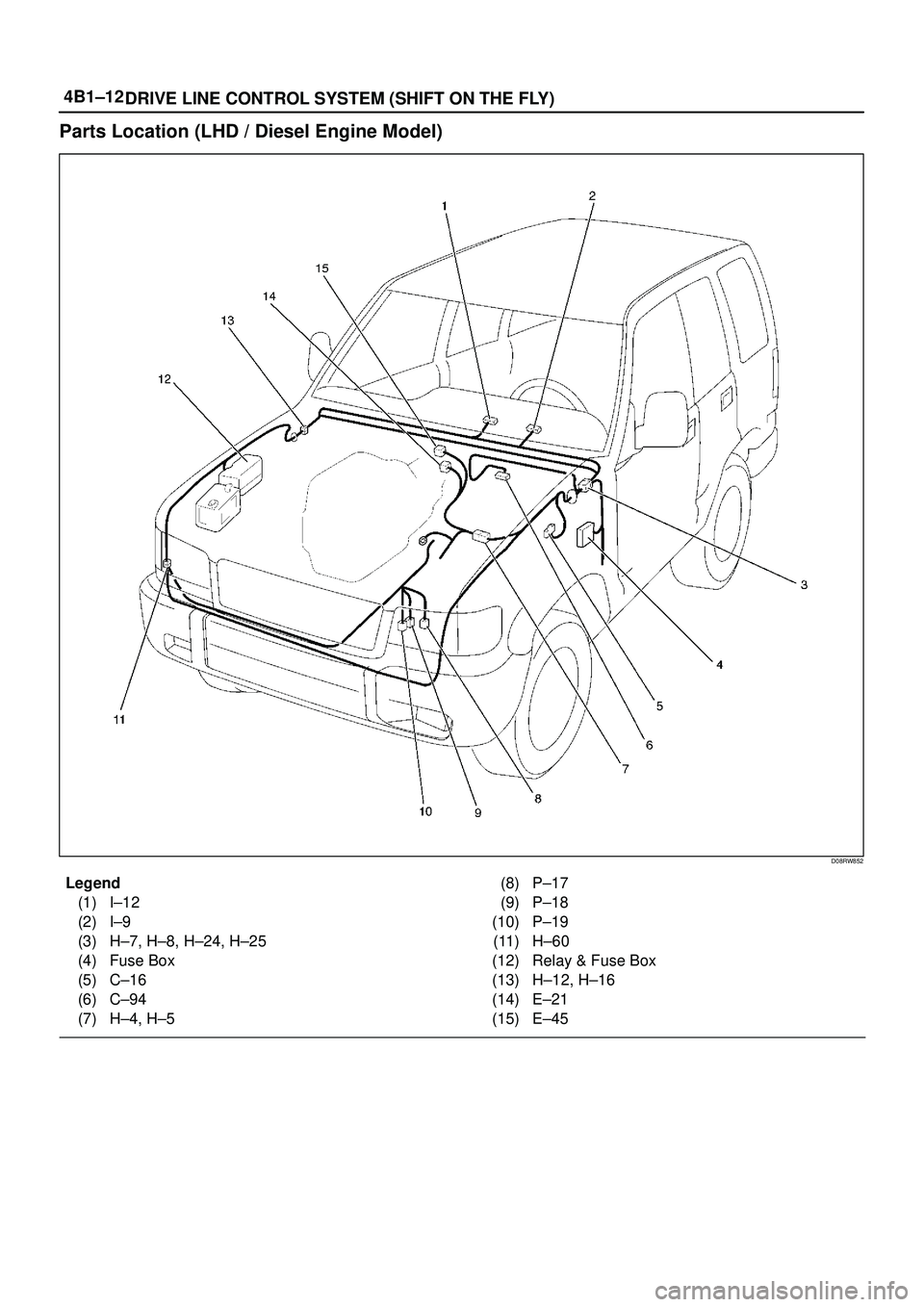
Parts Location (LHD / Diesel Engine Model)
D08RW852
Legend
(1) I±12
(2) I±9
(3) H±7, H±8, H±24, H±25
(4) Fuse Box
(5) C±16
(6) C±94
(7) H±4, H±5(8) P±17
(9) P±18
(10) P±19
(11) H±60
(12) Relay & Fuse Box
(13) H±12, H±16
(14) E±21
(15) E±45
Page 546 of 3573
4B1±13 DRIVE LINE CONTROL SYSTEM (SHIFT ON THE FLY)
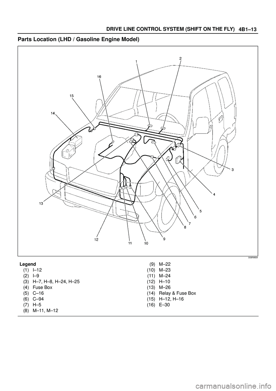
Parts Location (LHD / Gasoline Engine Model)
D08RW854
Legend
(1) I±12
(2) I±9
(3) H±7, H±8, H±24, H±25
(4) Fuse Box
(5) C±16
(6) C±94
(7) H±5
(8) M±11, M±12(9) M±22
(10) M±23
(11) M±24
(12) H±10
(13) M±26
(14) Relay & Fuse Box
(15) H±12, H±16
(16) E±30
Page 547 of 3573
4B1±14
DRIVE LINE CONTROL SYSTEM (SHIFT ON THE FLY)
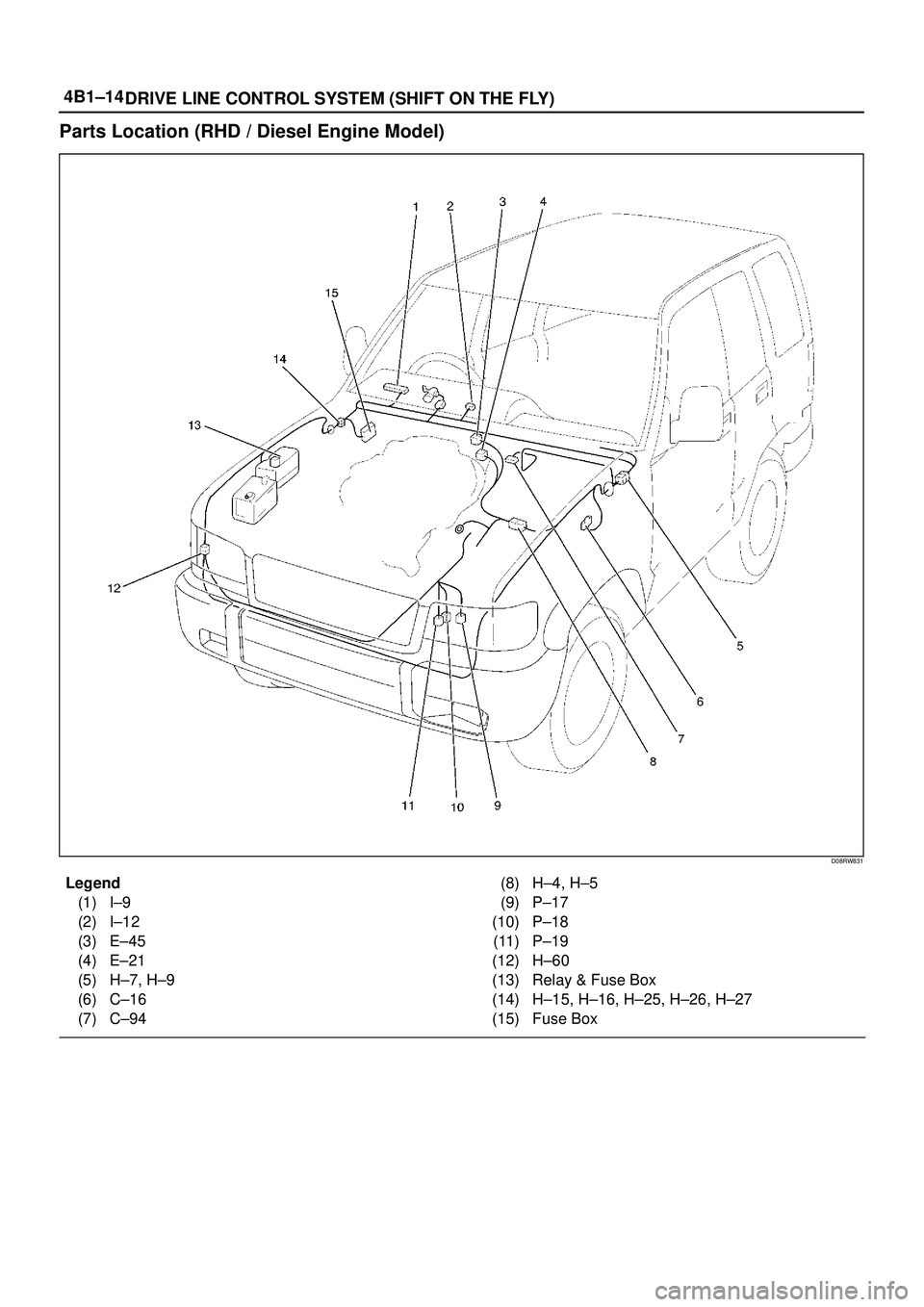
Parts Location (RHD / Diesel Engine Model)
D08RW831
Legend
(1) I±9
(2) I±12
(3) E±45
(4) E±21
(5) H±7, H±9
(6) C±16
(7) C±94(8) H±4, H±5
(9) P±17
(10) P±18
(11) P±19
(12) H±60
(13) Relay & Fuse Box
(14) H±15, H±16, H±25, H±26, H±27
(15) Fuse Box
Page 548 of 3573
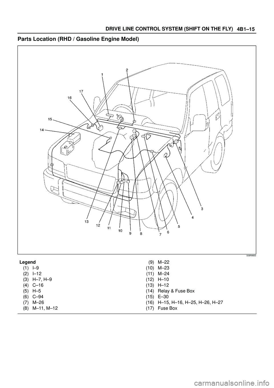
4B1±15 DRIVE LINE CONTROL SYSTEM (SHIFT ON THE FLY)
Parts Location (RHD / Gasoline Engine Model)
D08RW853
Legend
(1) I±9
(2) I±12
(3) H±7, H±9
(4) C±16
(5) H±5
(6) C±94
(7) M±26
(8) M±11, M±12(9) M±22
(10) M±23
(11) M±24
(12) H±10
(13) H±12
(14) Relay & Fuse Box
(15) E±30
(16) H±15, H±16, H±25, H±26, H±27
(17) Fuse Box
Page 811 of 3573
5A±1 BRAKE CONTROL SYSTEM
BRAKES
CONTENTS
Brake Control System 5A. . . . . . . . . . . . . . . . . . . .
Anti±lock Brake System 5B. . . . . . . . . . . . . . . . . . Power±Assisted Brake System 5C. . . . . . . . . . . .
Parking Brakes 5D. . . . . . . . . . . . . . . . . . . . . . . . .
BRAKE CONTROL SYSTEM
CONTENTS
Service Precaution 5A±2. . . . . . . . . . . . . . . . . . . . . .
General Description 5A±3. . . . . . . . . . . . . . . . . . . . .
System Components 5A±3. . . . . . . . . . . . . . . . . . .
Electronic Hydraulic Control Unit (EHCU) 5A±3.
ABS Warning Light 5A±4. . . . . . . . . . . . . . . . . . . .
Wheel Speed Sensor 5A±4. . . . . . . . . . . . . . . . . .
G-Sensor 5A±4. . . . . . . . . . . . . . . . . . . . . . . . . . . . .
Normal and Anti-lock Braking 5A±4. . . . . . . . . . .
Brake Pedal Travel 5A±4. . . . . . . . . . . . . . . . . . . .
Acronyms and Abbreviations 5A±4. . . . . . . . . . . .
General Diagnosis 5A±5. . . . . . . . . . . . . . . . . . . . . . .
General Information 5A±5. . . . . . . . . . . . . . . . . . . .
ABS Service Precautions 5A±5. . . . . . . . . . . . . . .
Computer System Service Precautions 5A±5. . .
General Service Precautions 5A±5. . . . . . . . . . . .
Note on Intermittents 5A±5. . . . . . . . . . . . . . . . . . .
Test Driving ABS Complaint Vehicles 5A±6. . . . .
ªABSº Warning Light 5A±6. . . . . . . . . . . . . . . . . . .
Normal Operation 5A±6. . . . . . . . . . . . . . . . . . . . .
Basic Diagnostic Flow Chart 5A±6. . . . . . . . . . . .
Basic Inspection Procedure 5A±7. . . . . . . . . . . . .
Tech 2 Scan Tool 5A±8. . . . . . . . . . . . . . . . . . . . . .
Getting Started 5A±9. . . . . . . . . . . . . . . . . . . . . . . .
Operating Procedure 5A±10. . . . . . . . . . . . . . . . . . .
Data List 5A±11. . . . . . . . . . . . . . . . . . . . . . . . . . . . .
EHCU Connector Pin-out Checks 5A±12. . . . . . . .
Circuit Diagram (LHD model / 6VD1 and
4JG2) 5A±13. . . . . . . . . . . . . . . . . . . . . . . . . . . . . . .
Circuit Diagram (LHD model / 4JG2) 5A±14. . . . .
Circuit Diagram (LHD model / 4JG2) 5A±15. . . . .
Circuit Diagram (LHD model / 6VD1) 5A±16. . . . .
Circuit Diagram (LHD model / 6VD1) 5A±17. . . . .
Connector List (LHD model) 5A±18. . . . . . . . . . . .
Part Location (LHD model) 5A±20. . . . . . . . . . . . . .
Circuit Diagram (RHD model / 6VD1 and
4JG2) 5A±21. . . . . . . . . . . . . . . . . . . . . . . . . . . . . . .
Circuit Diagram (RHD model / 4JG2) 5A±22. . . . .
Circuit Diagram (RHD model / 4JG2) 5A±23. . . . .
Circuit Diagram (RHD model / 6VD1) 5A±24. . . . .
Circuit Diagram (RHD model / 6VD1) 5A±25. . . . .
Circuit Diagram (RHD model / 6VE1 and
4JX1) 5A±26. . . . . . . . . . . . . . . . . . . . . . . . . . . . . . . . Circuit Diagram (RHD model / 4JX1) 5A±27. . . . .
Circuit Diagram (RHD model / 4JX1) 5A±28. . . . .
Circuit Diagram (RHD model / 6VE1) 5A±29. . . . .
Circuit Diagram (RHD model / 6VE1) 5A±30. . . . .
Connector List (RHD model) 5A±31. . . . . . . . . . . .
Part Location (RHD model) 5A±34. . . . . . . . . . . . .
Symptom Diagnosis 5A±35. . . . . . . . . . . . . . . . . . . . .
Chart A±1 ABS Works Frequently But
Vehicle Does Not Decelerate 5A±35. . . . . . . . . . .
Chart TA-1 ABS Works Frequently But
Vehicle Does Not Decelerate (Use
TECH 2) 5A±36. . . . . . . . . . . . . . . . . . . . . . . . . . . . .
Chart A-2 Uneven Braking Occurs While
ABS Works 5A±36. . . . . . . . . . . . . . . . . . . . . . . . . . .
Chart A-3, TA-3 The Wheels Are Locked 5A±36.
Chart A-4 Brake Pedal Feed Is Abnormal 5A±37.
Chart A-5, TA-5 Braking Sound (From
EHCU) Is Heard While Not Braking 5A±38. . . . . .
Diagnostic Trouble Codes 5A±39. . . . . . . . . . . . . . . .
Diagnosis By ªABSº Warning Light
Illumination Pattern 5A±40. . . . . . . . . . . . . . . . . . . . .
Diagnostic Trouble Codes (DTCs) 5A±40. . . . . . .
Chart B-1 With the key in the ON position
(Before starting the engine). Warning light
(W/L) is not activated. 5A±43. . . . . . . . . . . . . . . . .
Chart B-2 EHCU Abnormality (DTC 14) 5A±43. . .
Chart B-3 Power Voltage Drop (DTC 15) 5A±44. .
Chart B-4 CLASS-2 Communication Line
Abnormality (DTC 16) 5A±44. . . . . . . . . . . . . . . . .
Chart B-5 G-Sensor Circuit (DTC 21) 5A±45. . . . .
Chart B-6 Abnormal Transmission Input
(DTC 23) 5A±46. . . . . . . . . . . . . . . . . . . . . . . . . . . .
Chart B-7 Transfer Monitor (DTC 24) 5A±47. . . . .
Chart B-8 EHCU Pump Motor And Motor
Relay Circuit (DTC 32) 5A±47. . . . . . . . . . . . . . . . .
Chart B-9 EHCU Pump Valve And Valve
Relay Circuit (DTC 35) 5A±47. . . . . . . . . . . . . . . . .
Chart B-10 FL Isolation Solenoid Valve
Abnormality (DTC 41) 5A±48. . . . . . . . . . . . . . . . .
Chart B-11 FL Dump Solenoid Valve
Abnormality (DTC 42) 5A±48. . . . . . . . . . . . . . . . .
Chart B-12 FR Isolation Solenoid Valve
Abnormality (DTC 43) 5A±48. . . . . . . . . . . . . . . . .
Chart B-13 FR Dump Solenoid Valve
Abnormality (DTC 44) 5A±49. . . . . . . . . . . . . . . . .
Chart B-14 Rear Isolation Solenoid Valve
Abnormality (DTC 45) 5A±49. . . . . . . . . . . . . . . . .
Chart B-15 Rear Dump Solenoid Valve
Abnormality (DTC 46) 5A±49. . . . . . . . . . . . . . . . .