JAGUAR S TYPE 1999 1.G Powertrain Manual
Manufacturer: JAGUAR, Model Year: 1999, Model line: S TYPE, Model: JAGUAR S TYPE 1999 1.GPages: 75, PDF Size: 3.4 MB
Page 41 of 75

V6 Engine AJ-V6/AJ28
36
Fail Safe Cooling System
A unique feature of the V6 engine is the use of a fail safe cooling strategy, controlled by the EMS, in the
event of coolant loss leading to rising engine temperatures. The principle of the strategy involves
switching off one or more fuel injectors to inhibit combustion and reduce heat, thus allowing the flow of
ambient intake air to further cool the selected cylinders. By cycling the selected cylinders, ie switching
different injectors off for a period and in a sequence determined by EMS parameters, overall engine
temperature can be controlled sufficiently to allow the vehicle to be driven, at reduced power, for a
short distance. Throughout the malfunction period, instrument panel messages and warnings advise the
driver of the current status of the cooling system as described below.
Driver Indication and EMS Action
The fail safe strategy moves though different stages depending on engine temperature:
¥ Temperatures below 122û C (250û F) are within the normal range. At high temperatures below this
level the temperature gauge pointer enters the red zone.
¥ If the temperature rises to between 122û C - 127û C (250û F to 260û F) no action is taken by the EMS
which affects engine running but the following indications appear:
Temperature gauge pointer in red zone
Message Centre HIGH ENGINE TEMPERATURE
Warning light TEMP
Priority light red
Audible indicator single chime sounded
¥ If the temperature rises to 127û C (260û F) or above, the fail safe strategy operates. At 127û C (260û F),
the EMS will cut out one cylinder (the selected cylinder is varied) and as the temperature continues
to rise, this will increase to a maximum of three cylinders cut (with cylinder cycling). The following
indications are given:
Temperature gauge pointer in red zone
Message Centre ENGINE POWER REDUCED
Warning light TEMP
Priority light red
Audible indicator three chimes sounded
¥ At 166û C (300û F) or above, the fail safe strategy continues as described but the following
indications are given:
Temperature gauge pointer in red zone
Message Centre PULL OFF ROAD SAFELY alternates with TURN OFF IGNITION
Warning light TEMP flashes
Priority light red
Audible indicator five chimes sounded
¥ EMS shuts the engine down.
Page 42 of 75
V6 EngineAJ-V6/AJ28
37
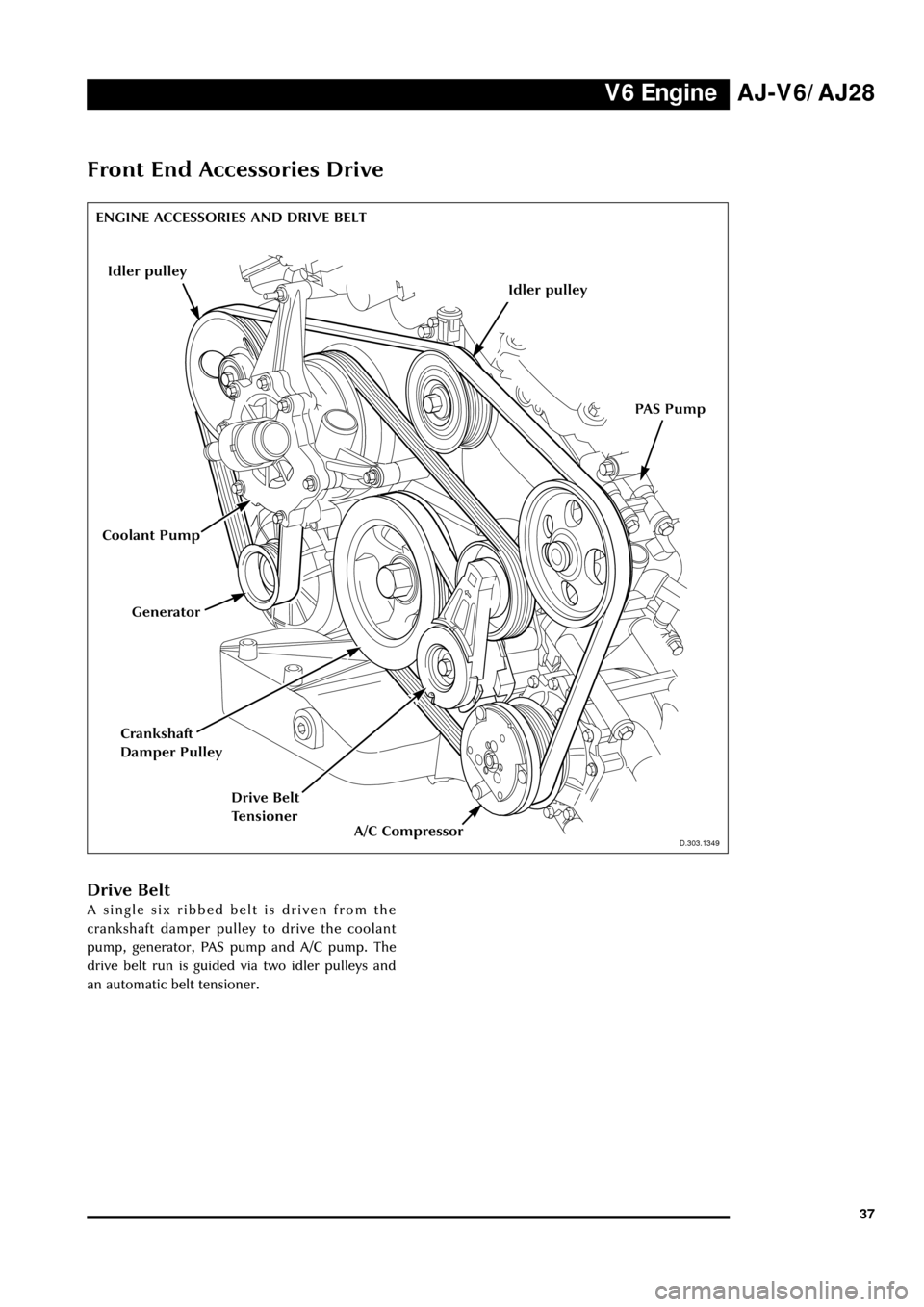
Front End Accessories Drive
D.303.1349
Drive Belt
A single six ribbed belt is driven from the
crankshaft damper pulley to drive the coolant
pump, generator, PAS pump and A/C pump. The
drive belt run is guided via two idler pulleys and
an automatic belt tensioner.
PAS Pump
Generator
D.303.1349
ENGINE ACCESSORIES AND DRIVE BELT
Coolant Pump
A/C Compressor
Drive Belt
Tensioner
Crankshaft
Damper Pulley
Idler pulley
Idler pulley
Page 43 of 75
V6 Engine AJ-V6/AJ28
38
J.303.1348
Generator
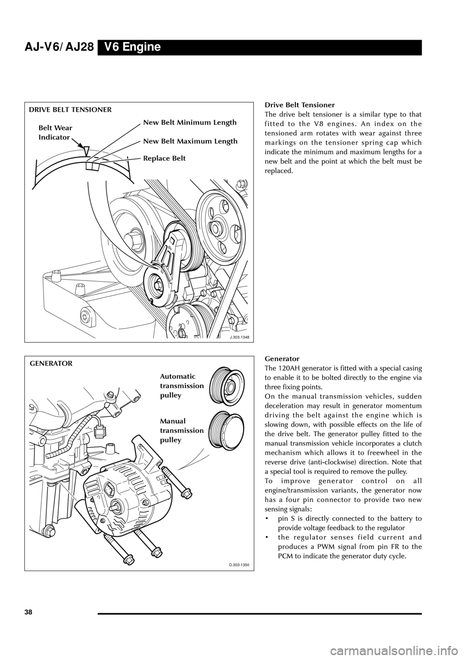
The 120AH generator is fitted with a special casing
to enable it to be bolted directly to the engine via
three fixing points.
On the manual transmission vehicles, sudden
deceleration may result in generator momentum
driving the belt against the engine which is
slowing down, with possible effects on the life of
the drive belt. The generator pulley fitted to the
manual transmission vehicle incorporates a clutch
mechanism which allows it to freewheel in the
reverse drive (anti-clockwise) direction. Note that
a special tool is required to remove the pulley.
To improve generator control on all
engine/transmission variants, the generator now
has a four pin connector to provide two new
sensing signals:
¥ pin S is directly connected to the battery to
provide voltage feedback to the regulator
¥ the regulator senses field current and
produces a PWM signal from pin FR to the
PCM to indicate the generator duty cycle.
D.303.1350
DRIVE BELT TENSIONER
GENERATOR
D.303-1350
Drive Belt Tensioner
The drive belt tensioner is a similar type to that
fitted to the V8 engines. An index on the
tensioned arm rotates with wear against three
markings on the tensioner spring cap which
indicate the minimum and maximum lengths for a
new belt and the point at which the belt must be
replaced.
Replace Belt
Belt Wear
Indicator
New Belt Maximum Length
New Belt Minimum Length
Manual
transmission
pulleyAutomatic
transmission
pulley
J.303.1348
Page 44 of 75
V6 EngineAJ-V6/AJ28
39
D.303.1351D.303.1352
PAS PUMPA/C COMPRESSOR
D.303.1352
D.303.1369
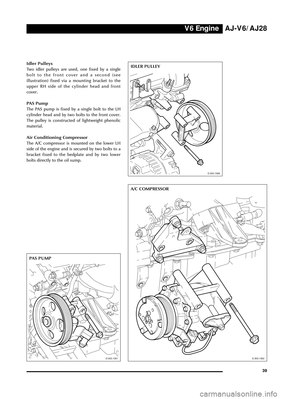
Idler Pulleys
Two idler pulleys are used, one fixed by a single
bolt to the front cover and a second (see
illustration) fixed via a mounting bracket to the
upper RH side of the cylinder head and front
cover.
PAS Pump
The PAS pump is fixed by a single bolt to the LH
cylinder head and by two bolts to the front cover.
The pulley is constructed of lightweight phenolic
material.
Air Conditioning Compressor
The A/C compressor is mounted on the lower LH
side of the engine and is secured by two bolts to a
bracket fixed to the bedplate and by two lower
bolts directly to the oil sump.IDLER PULLEY
D.303.1351
D.303.1369
Page 45 of 75
V6 Engine AJ-V6/AJ28
40
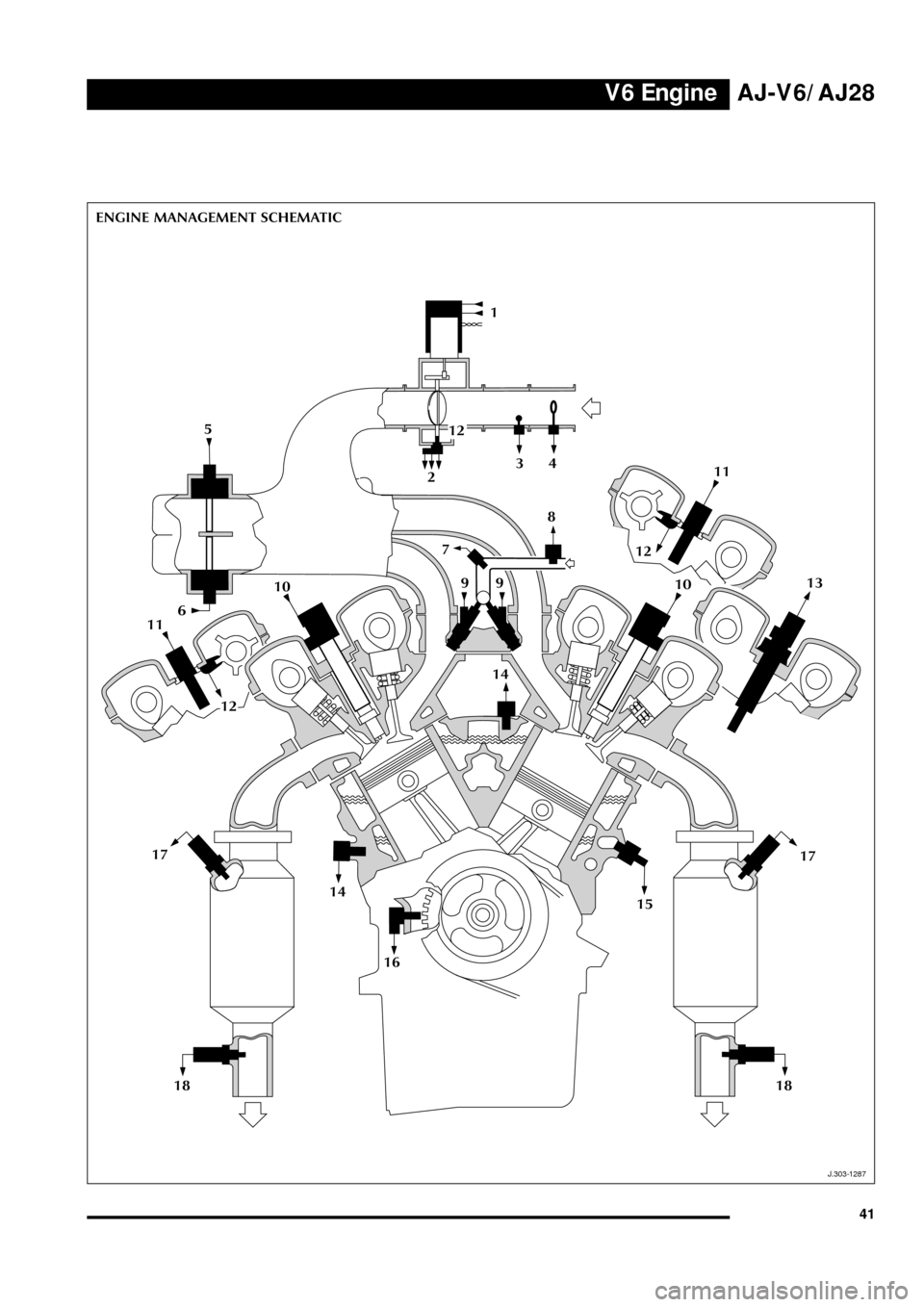
Engine Management Sensors
Key to illustration on page 41:
1. Throttle motor
2. TP sensor
3. IAT sensor
4. MAF sensor
5. Top IMT valve
6. Bottom IMT valve
7. EFT sensor
8. IP sensor
9. Fuel injectors
10. Coil-on-plug units
11. VVT shuttle valve
12. CMP sensor
13. CHT sensor
14. KS sensors
15. EOT sensor
16. CKP sensor
17. HO2 sensors
18. HO2 sensors (catalyst monitors)
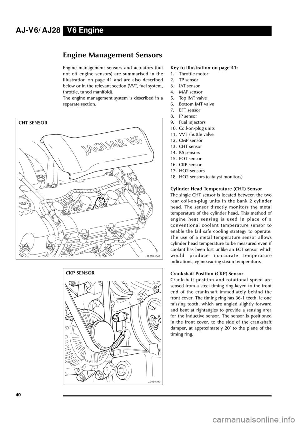
Cylinder Head Temperature (CHT) Sensor
The single CHT sensor is located between the two
rear coil-on-plug units in the bank 2 cylinder
head. The sensor directly monitors the metal
temperature of the cylinder head. This method of
engine heat sensing is used in place of a
conventional coolant temperature sensor to
enable the fail safe cooling strategy to operate.
The use of a metal temperature sensor allows
cylinder head temperature to be measured even if
coolant has been lost unlike an ECT sensor which
would produce inaccurate temperature
indications, eg measuring steam temperature.
Crankshaft Position (CKP) Sensor
Crankshaft position and rotational speed are
sensed from a steel timing ring keyed to the front
end of the crankshaft immediately behind the
front cover. The timing ring has 36-1 teeth, ie one
missing tooth, which are angled slightly forward
and bent at rightangles to provide a sensing area
for the inductive sensor. The sensor is positioned
in the front cover, to the side of the crankshaft
damper, at approximately 20û to the plane of the
timing ring.
D.303.1342
J.303.1343
CHT SENSOR
CKP SENSOR
D.303-1342
J.303-1343
Engine management sensors and actuators (but
not off engine sensors) are summarised in the
illustration on page 41 and are also described
below or in the relevant section (VVT, fuel system,
throttle, tuned manifold).
The engine management system is described in a
separate section.
Page 46 of 75
V6 EngineAJ-V6/AJ28
41
J.303.1287
ENGINE MANAGEMENT SCHEMATIC
1
324 5
12
6
8
14
15 7
9
111013
16
J.303-1287
9
1011
12
1214
18 17
1817
Page 47 of 75
V6 Engine AJ-V6/AJ28
42
J.303.1291
KS SENSORS
J.303-1291
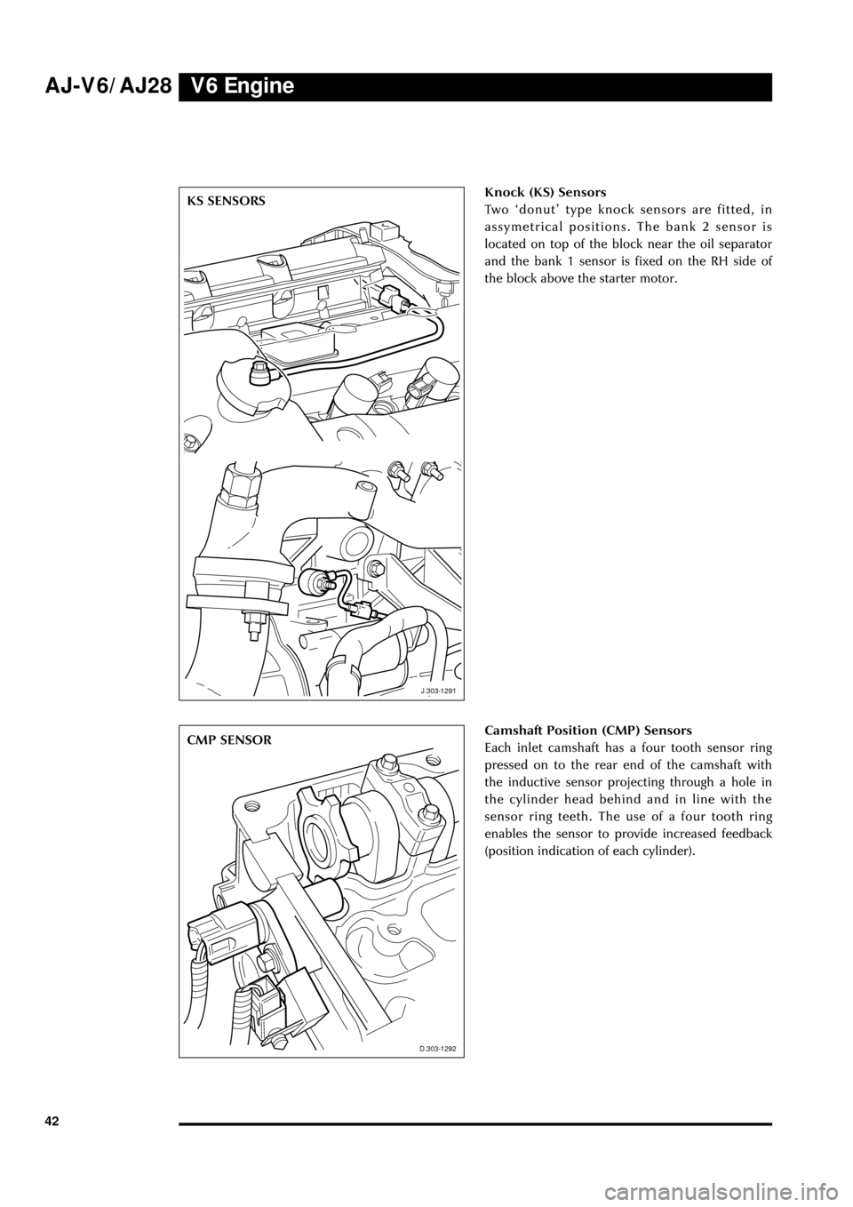
Knock (KS) Sensors
Two ÔdonutÕ type knock sensors are fitted, in
assymetrical positions. The bank 2 sensor is
located on top of the block near the oil separator
and the bank 1 sensor is fixed on the RH side of
the block above the starter motor.
D.303.1292
CMP SENSOR
D.303-1292
Camshaft Position (CMP) Sensors
Each inlet camshaft has a four tooth sensor ring
pressed on to the rear end of the camshaft with
the inductive sensor projecting through a hole in
the cylinder head behind and in line with the
sensor ring teeth. The use of a four tooth ring
enables the sensor to provide increased feedback
(position indication of each cylinder).
Page 48 of 75
V6 EngineAJ-V6/AJ28
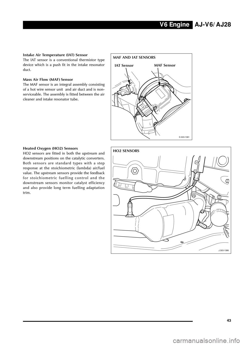
43 Intake Air Temperature (IAT) Sensor
The IAT sensor is a conventional thermistor type
device which is a push fit in the intake resonator
duct.
Mass Air Flow (MAF) Sensor
The MAF sensor is an integral assembly consisting
of a hot wire sensor unit and air duct and is non-
serviceable. The assembly is fitted between the air
cleaner and intake resonator tube.
D.303.1381
MAF AND IAT SENSORS
D.303-1381
J.303.1386
HO2 SENSORS
J.303-1386
Heated Oxygen (HO2) Sensors
HO2 sensors are fitted in both the upstream and
downstream positions on the catalytic converters.
Both sensors are standard types with a step
response at the stoichiometric (lambda) air/fuel
value. The upstream sensors provide the feedback
for stoichiometric fuelling control and the
downstream sensors monitor catalyst efficiency
and also provide long term fuelling adaptation
trim.
MAF SensorIAT Sensor
Page 49 of 75

Notes AJ-V6/AJ28
44
Page 50 of 75
V8 EngineAJ-V6/AJ28
45
Introduction
The AJ28 engine is a variant of the 4.0L 90û V8 units fitted to the XJ and XK range of vehicles. The AJ28
shares some of the changes incorporated in the current AJ27 engine: both engines are derived from the
original AJ26 unit. A number of features are unique to the AJ28 or are shared with the AJ-V6 engine also
described in this publication.
Features of the AJ28 engine are:
¥ Continuously variable inlet valve timing over a 48û
+
-2û crank angle: as fitted to the AJ27 engine
¥ Full authority cable-less electronic throttle control: as fitted to the AJ-V6 engine
¥ Air assisted fuel injection: similar to system used on the AJ27 engine
¥ Unique induction manifold with centrally mounted throttle body
¥ Returnless fuel system: similar to AJ-V6 engine
¥ Twin wall exhaust manifold
¥ Engine management system as used on the AJ-V6
¥ New sensors
¥ Modified sump and oil cooler
¥ Modified front end ancillary drive and components
Engine Specification
Maximum power DIN - 209 kW (281 BHP) at 6100 RPM
EEC - 203 kW (276 PS) at 6100 RPM
Maximum torque DIN - 390 Nm (287 lbft) at 4300 RPM
EEC - 278 Nm (279 lbft) at 4300 RPM
Oil Specification
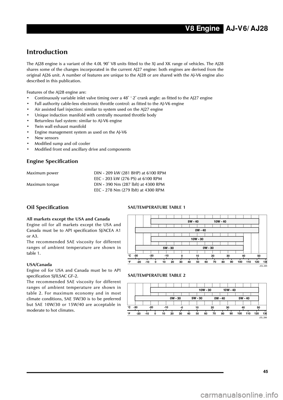
All markets except the USA and Canada
Engine oil for all markets except the USA and
Canada must be to API specification SJ/ACEA A1
or A3.
The recommended SAE viscosity for different
ranges of ambient temperature are shown in
table 1.
USA/Canada
Engine oil for USA and Canada must be to API
specification SJ/ILSAC GF-2.
The recommended SAE viscosity for different
ranges of ambient temperature are shown in
table 2. For maximum economy and in most
climate conditions, SAE 5W/30 is to be preferred
but SAE 10W/30 or 15W/40 are acceptable in
moderate to hot climates.
JOL.29550
50JOL.296
SAE/TEMPERATURE TABLE 2
SAE/TEMPERATURE TABLE 1