Abs JAGUAR S TYPE 2005 1.G Technical Guide Update
[x] Cancel search | Manufacturer: JAGUAR, Model Year: 2005, Model line: S TYPE, Model: JAGUAR S TYPE 2005 1.GPages: 133, PDF Size: 3.48 MB
Page 62 of 133
JAGUARS-TYPEChassis
57
D.206.176
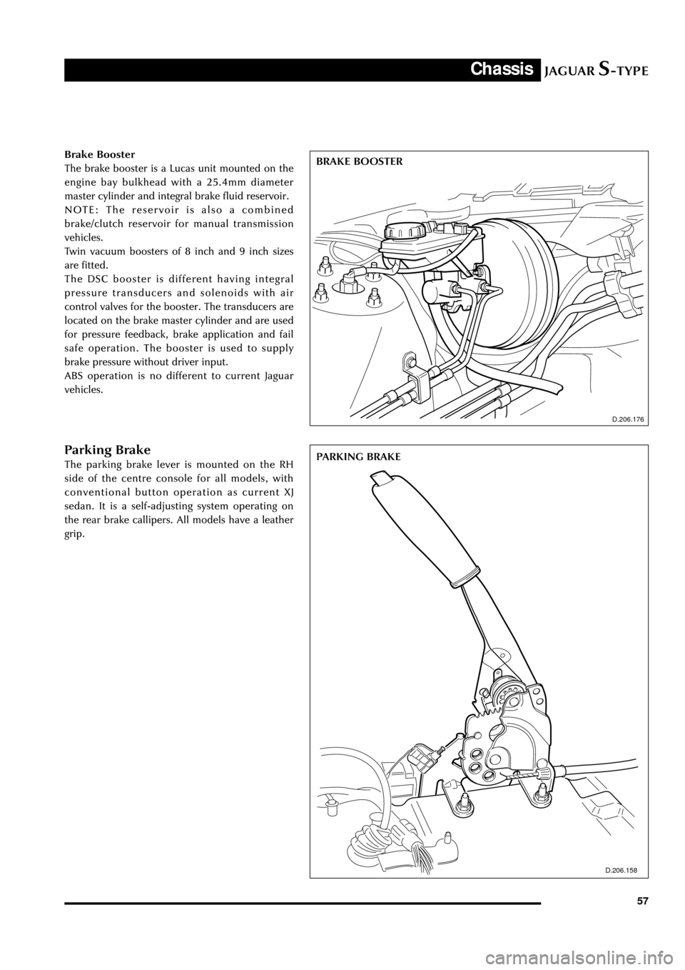
BRAKE BOOSTER Brake Booster
The brake booster is a Lucas unit mounted on the
engine bay bulkhead with a 25.4mm diameter
master cylinder and integral brake fluid reservoir.
NOTE: The reservoir is also a combined
brake/clutch reservoir for manual transmission
vehicles.
Twin vacuum boosters of 8 inch and 9 inch sizes
are fitted.
The DSC booster is different having integral
pressure transducers and solenoids with air
control valves for the booster. The transducers are
located on the brake master cylinder and are used
for pressure feedback, brake application and fail
safe operation. The booster is used to supply
brake pressure without driver input.
ABS operation is no different to current Jaguar
vehicles.
Parking Brake
The parking brake lever is mounted on the RH
side of the centre console for all models, with
conventional button operation as current XJ
sedan. It is a self-adjusting system operating on
the rear brake callipers. All models have a leather
grip.
D.206.158
PARKING BRAKE
Page 77 of 133
JAGUARS-TYPEElectrical/Electronic
72
Module Communications Network
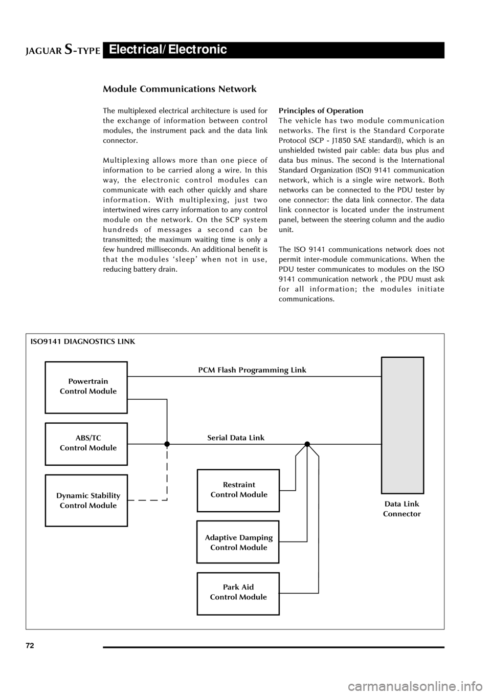
ISO9141 DIAGNOSTICS LINK
Powertrain
Control Module
ABS/TC
Control Module
Dynamic Stability
Control Module
Restraint
Control Module
Adaptive Damping
Control Module
Park Aid
Control Module
Data Link
Connector
PCM Flash Programming Link
Serial Data Link The multiplexed electrical architecture is used for
the exchange of information between control
modules, the instrument pack and the data link
connector.
Multiplexing allows more than one piece of
information to be carried along a wire. In this
way, the electronic control modules can
communicate with each other quickly and share
information. With multiplexing, just two
intertwined wires carry information to any control
module on the network. On the SCP system
hundreds of messages a second can be
transmitted; the maximum waiting time is only a
few hundred milliseconds. An additional benefit is
that the modules ÔsleepÕ when not in use,
reducing battery drain.Principles of Operation
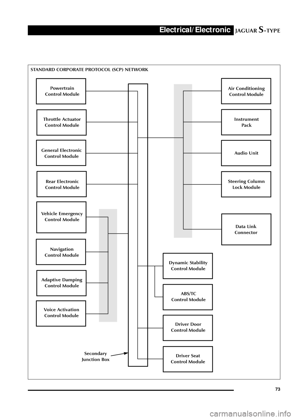
The vehicle has two module communication
networks. The first is the Standard Corporate
Protocol (SCP - J1850 SAE standard)), which is an
unshielded twisted pair cable: data bus plus and
data bus minus. The second is the International
Standard Organization (ISO) 9141 communication
network, which is a single wire network. Both
networks can be connected to the PDU tester by
one connector: the data link connector. The data
link connector is located under the instrument
panel, between the steering column and the audio
unit.
The ISO 9141 communications network does not
permit inter-module communications. When the
PDU tester communicates to modules on the ISO
9141 communication network , the PDU must ask
for all information; the modules initiate
communications.
Page 78 of 133
JAGUARS-TYPEElectrical/Electronic
73 STANDARD CORPORATE PROTOCOL (SCP) NETWORK
Powertrain
Control Module
Vehicle Emergency
Control Module
Throttle Actuator
Control Module
General Electronic
Control Module
Rear Electronic
Control Module
Navigation
Control Module
Adaptive Damping
Control Module
Voice Activation
Control Module
Air Conditioning
Control Module
Data Link
Connector
Instrument
Pack
Audio Unit
Steering Column
Lock Module
Dynamic Stability
Control Module
Secondary
Junction BoxDriver Seat
Control Module
Driver Door
Control Module
ABS/TC
Control Module
Page 79 of 133
JAGUARS-TYPEElectrical/Electronic
74The SCP communication network will remain
operational even with severing of one of the bus
wires. Communications will also continue if one
of the bus wires is shorted to ground or battery
positive voltage (B+), or if some , but not all,
termination resistors are lost.
Unlike the SCP communication network, the
ISO 9141 communication network will not
function if the wire is shorted to ground or battery
positive voltage (B+). Also, if one of the modules
on the ISO 9141 network loses power or shorts
internally, communication to that module will fail.
Control Modules
The vehicle control module functions are
described briefly below (for further information
refer to the relevant sections throughout the
Guide).
Anti Lock Brake/Traction Control and
Dynamic Stability Control, Control Modules
The anti-lock brake control module is connected
to the SCP communication network. The module
comes in two forms. The first type is the standard
equipped anti-lock brake system (ABS) with
traction control (TC). It controls the brake
pressure to the four wheels to keep the vehicle
under control while braking.
The second type of ABS is optional and is called
dynamic stability control (DSC). This control
module adds yaw sensors to the package to help
in sensing a loss of vehicle control.
Audio Control Unit
The audio control unit is connected to the SCP
communication network and also to the audio
control protocol (ACP) communication network.
The audio control unit communicates with the
compact disc and the cellular phone transceiver.
Driver Door Control Module (DDCM)
DDCM is connected to the SCP communication
network. The module controls many functions
including power windows, driver mirror, power
locks, and keyless remote entry.Driver Seat Control Module (DSCM)
The DSCM is connected to the SCP
communication network. The DSCM is located
under the driver seat and controls the seat
positions. The module also communicates with the
DDCM to control the driver seat memory
functions.
Control Module Locations
Key to illustration on following page:
1.Anti-lock brake system/Traction control
system or Dynamic stability control
(ABS/TCCM or DSCCM)
(non-handed)
2.Throttle actuator control module (TACM)
(non-handed)
3.Powertrain control module (PCM) (handed)
4.Air conditioning control module (A/CCM)
(non-handed)
5.Restraint control module (RCM) (non-handed)
6.Sliding roof control module (SRCM)
(non-handed)
7.Passenger seat heater control module
(PSHCM) (non-handed)
8.Rear electronic control module (RECM)
(non-handed)
9.Vehicle information control module (VICM)
(Japan only)
10.Adaptive damping control module (ADCM)
(non-handed)
11.Parking aid control module (PACM)
(non-handed)
12.Navigation control module (NCM)
(non-handed)
13.Vehicle emergency control module (VECM)
(non-handed)
14.Voice-activated control module (VACM)
(non-handed)
15.Cellular telephone control module (CTCM)
(non-handed)
16.Driver seat heater control module (DSHCM)
(non-handed)
17.Driver seat control module (DSCM) (handed)
18.Driver door control module (DDCM)
(handed)
19.Instrument pack (handed)
20.General electronics control module (GECM)
(non-handed)
21.Steering column lock module (SCLM) (handed)
Page 86 of 133

JAGUARS-TYPEElectrical/Electronic
81 No Type Rating (amps) Colour Circuit
10 - - - Not used
11 mini 15 Blue HO2 sensor (catalyst)
12 mini 10 Red Coil on plug
13 cartridge 40 or 30 Green or Pink RH heated windshield or heated wiper
park (where fitted)
14 - - - Not used
15 cartridge 40 Green LH heated windshield
16 cartridge 30 Pink Blower motor
17 - - - Not used
18 cartridge 40 Green Powertrain control module (PCM)
19 - - - Not used
20 - - - Not used
21 cartridge 30 Pink Starter solenoid
22 cartridge 30 Pink ABS motor
23 cartridge 20 Blue Wiper motor
24 cartridge 30 Pink Head lamp washer pump
25 cartridge 80 - Cooling fan motor
Diode 1 PCM
Passenger Compartment Fusebox
No Type Rating (amps) Colour Circuit
1 mini 5 Brown Starter relay coil via Park/Neutral switch
2 mini 5 Brown Radio
3 mini 5 Brown ABS/DSC module
4 mini 5 Brown PCM relay coil, instrument pack, RECM,
fuel pump relay, transit relay
5 mini 5 Brown Autolamp sensor, heated seat module
switch & overdrive cancel switch RSM, BSI
6 mini 10 Red OBDII
7 mini 5 Brown DDCM, DSCM, PCM, Anti-theft LED,
security horn, power mirror
8 mini 5 Brown Right-front direction indicators, side
repeaters, side markers, park lights
9 mini 10 Red Right-front low beam headlamp
10 mini 5 Brown Left-front direction indicators side
repeaters, side markers, park lamps
11 mini 10 Red Left-front main beam lamp
12 mini 10 Red Headlamp levelling, ABS/DSC module
13 mini 5 Brown Instrument pack
14 mini 10 Red RCM, Dual Automatic Temperature
Control (DATC) module
Page 100 of 133
JAGUARS-TYPEElectrical/Electronic
95
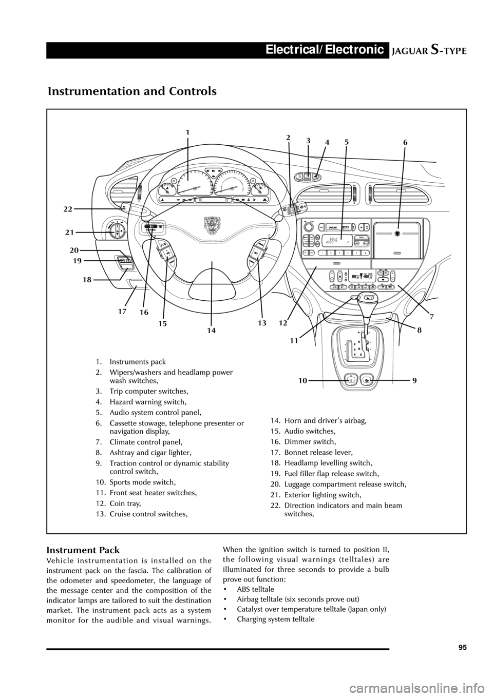
Instrumentation and Controls
1. Instruments pack
2. Wipers/washers and headlamp power
wash switches,
3. Trip computer switches,
4. Hazard warning switch,
5. Audio system control panel,
6. Cassette stowage, telephone presenter or
navigation display,
7. Climate control panel,
8. Ashtray and cigar lighter,
9. Traction control or dynamic stability
control switch,
10. Sports mode switch,
11. Front seat heater switches,
12. Coin tray,
13. Cruise control switches,
14. Horn and driverÕs airbag,
15. Audio switches,
16. Dimmer switch,
17. Bonnet release lever,
18. Headlamp levelling switch,
19. Fuel filler flap release switch,
20. Luggage compartment release switch,
21. Exterior lighting switch,
22. Direction indicators and main beam
switches,
1
7
8
9 10 11 12 13 19
16 17 18 20 21 22
142
3
45
6
15
Instrument Pack
Vehicle instrumentation is installed on the
instrument pack on the fascia. The calibration of
the odometer and speedometer, the language of
the message center and the composition of the
indicator lamps are tailored to suit the destination
market. The instrument pack acts as a system
monitor for the audible and visual warnings.When the ignition switch is turned to position II,
the following visual warnings (telltales) are
illuminated for three seconds to provide a bulb
prove out function:
¥ ABS telltale
¥ Airbag telltale (six seconds prove out)
¥ Catalyst over temperature telltale (Japan only)
¥ Charging system telltale
Page 127 of 133
JAGUARS-TYPE
Navigation
Electrical/Electronic
122
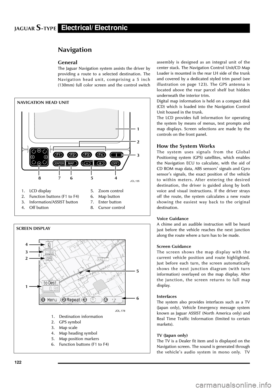
General
The Jaguar Navigation system assists the driver by
providing a route to a selected destination. The
Navigation head unit, comprising a 5 inch
(130mm) full color screen and the control switch
JOL.135
1. LCD display
2. Function buttons (F1 to F4)
3. Information/ASSIST button
4. Off button5. Zoom control
6. Map button
7. Enter button
8. Cursor control NAVIGATION HEAD UNIT
1
654
3
2
78assembly is designed as an integral unit of the
center stack. The Navigation Control Unit/CD Map
Loader is mounted in the rear LH side of the trunk
and covered by a dedicated styled trim panel (see
illustration on page 123). The GPS antenna is
located above the rear parcel shelf but hidden
underneath the interior trim.
Digital map information is held on a compact disk
(CD) which is loaded into the Navigation Control
Unit housed in the trunk.
The LCD provides full information for operating
the system by means of menus, text prompts and
map displays. Screen selections are made by the
controls on the front panel.
How the System Works
The system uses signals from the Global
Positioning system (GPS) satellites, which enables
the Navigation ECU to calculate, with the aid of
CD ROM map data, ABS sensorsÕ signals and Gyro
sensorÕs signals, the exact position of the vehicle
to within meters. After entering the desired
destination, the driver is guided along by both
voice and visual instructions. If the driver strays
off the route, the system calculates a new route
showing the easiest way back to the original
destination.
Voice Guidance
A chime and an audible instruction will be heard
just before the vehicle reaches the next junction
along the route where a turn has to be made.
Screen Guidance
The screen shows the map display with the
current vehicle position and route highlighted.
Just before each turn, the screen automatically
shows the next junction diagram (with turn
information) overlayed on the map display. After
the junction, the screen returns to full map
display.
Interfaces
The system also provides interfaces such as a TV
(Japan only), Vehicle Emergency message system
known as Jaguar ASSIST (North America only) and
Real Time Traffic Information (limited to certain
markets).
TV (Japan only)
The TV is a Dealer fit item and is displayed on the
Navigation screen. The sound is generated through
the vehicleÕs audio system in mono only. TV
JOL.178
1. Destination information
2. GPS symbol
3. Map scale
4. Map heading symbol
5. Map position markers
6. Function buttons (F1 to F4)
1
6
5
4
3
2 SCREEN DISPLAY