ECU JAGUAR S TYPE 2005 1.G Technical Guide Update
[x] Cancel search | Manufacturer: JAGUAR, Model Year: 2005, Model line: S TYPE, Model: JAGUAR S TYPE 2005 1.GPages: 133, PDF Size: 3.48 MB
Page 72 of 133

JAGUARS-TYPEClimate Control
67 Pipework
The suction hose and liquid line are a one-piece
assembly. A single screw connects them to the air
conditioning unit manifold at the bulkhead. A
further screw fixing and push-in clip secures them
at the side of the engine bay. The liquid line fixed
to the cooling module then joins with a block
fitting and the suction hose connects with a quick
connect fitting and routes across the underneath
of the cooling module to the compressor. The
compressor suction and discharge hoses are also a
one piece assembly.
A pressure transducer is fitted to the discharge
hose as it connects to the rear of the condenser.
The high side charge port is situated on the
manifold connecting to the receiver drier whilst
the low side is adjacent to the compressor behind
the LH front wheel.
The compressor is a 9Occ scroll, which is variable
from 100% to 30%. Compressor is standard
specification to all vehicles although package
makes them unique to V6 and V8.
Air Distribution
Air distribution is as follows:
¥ Defrost duct integral with the fascia.
¥ Face vents, plenum, manifold, centre face
duct, side face duct, side window demist duct
are all sub-assembled into the fascia.
¥ Driver and front seat passenger foot ducts are
installed in the fascia after it has been fitted
to the vehicle.
¥ Rear foot ducts are fitted to the underframe.
¥ Rear face duct fitted to transmission tunnel.
¥ Rear face vent fitted to console.
¥ Extractor boxes fitted in rear quarter panels.
All flaps are electric servo controlled and
comprise:
¥ Fresh/recirculation - heater/evaporator unit.
¥ Cold air bypass - heater/evaporator unit.
¥ Foot flap - mounted on plenum.
¥ Defrost flap - mounted on plenum.
¥ Face flap - mounted on plenum.
Sensors, for operation of the system, are:
¥ Ambient temperature sensor - located behind
the lower front grille.
¥ Solar sensor - fitted to the top centre of the
fascia at the defrost grille
¥ In-car sensor - aspirated from the plenum
venturi sensor mounted inboard of the
steering column.¥ Two heater air outlet sensors
¥ One evaporator air outlet sensor
Servicing
Routine servicing consists of particle filter
replacement.
Replaceable items on the climate control system
are:
¥ Servo complete with linkages
¥ Sensors
¥ Evaporator and seals
¥ Heater core and seals
¥ Blower motor
¥ Impeller/blower motor wheel
¥ Hoses
¥ Registers/vents
¥ Ducts, except the defrost
¥ Defrost and side window demist grilles
¥ Control unit
¥ Compressor
¥ Water pump
¥ Water valve
¥ Receiver/drier
¥ Condenser
There are no panel diagnostics but PDU facility is
available with extensive capability, similar to
current XJ and XK Series.
System refrigerant is R134a. Vehicle charge weight
is 800 gms and charging is through the high side
charge port only.
Oil type is WSH-MIC231-B and refill quantity is
180 cc -220 cc.
Special tools are hose clamp pliers and air-
conditioning hoses spring lock de-coupler.
General information
Ensure that the grille at the base of the windshield
is kept clear of leaves, snow or other obstructions.
A solar sensor is mounted on top of the fascia, in
the centre of the defrost grille, and this should not
be covered.
The air conditioning system should be run briefly
at least once each week with a cold setting to
prevent the seals from drying out with subsequent
refrigerant leaks.
When the engine and vehicle interior are cold the
fan speed may be low until the engine has warmed
up, this avoids excessively cold air being blown
into the cabin.
Page 81 of 133
JAGUARS-TYPEElectrical/Electronic
76Air Conditioning Control Module (A/CCM)
The A/CCM is connected to the SCP
communication network. The A/CCM controls
automatic climate functions that maintain the
vehicle at a constant temperature setting.
Instrument Pack
The instrument pack is connected to the SCP
communication network. The instrument pack
displays information received on the SCP
including speedometer, odometer, fuel, and
message center warnings. The instrument pack
also controls the passive anti-theft system (PATS).
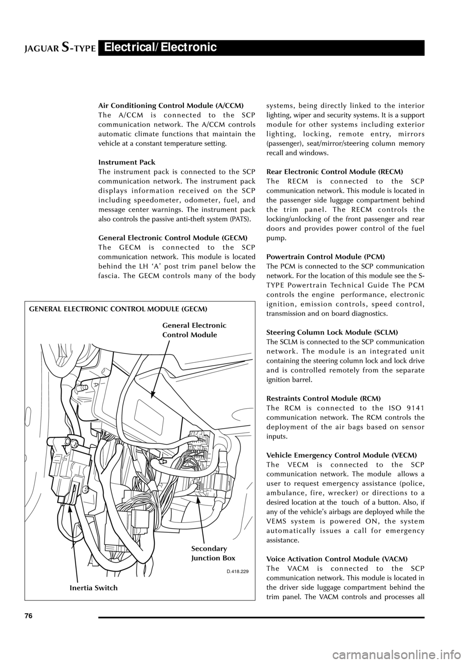
General Electronic Control Module (GECM)
The GECM is connected to the SCP
communication network. This module is located
behind the LH ÔAÕ post trim panel below the
fascia. The GECM controls many of the bodysystems, being directly linked to the interior
lighting, wiper and security systems. It is a support
module for other systems including exterior
lighting, locking, remote entry, mirrors
(passenger), seat/mirror/steering column memory
recall and windows.
Rear Electronic Control Module (RECM)
The RECM is connected to the SCP
communication network. This module is located in
the passenger side luggage compartment behind
the trim panel. The RECM controls the
locking/unlocking of the front passenger and rear
doors and provides power control of the fuel
pump.
Powertrain Control Module (PCM)
The PCM is connected to the SCP communication
network. For the location of this module see the S-
TYPE Powertrain Technical Guide The PCM
controls the engine performance, electronic
ignition, emission controls, speed control,
transmission and on board diagnostics.
Steering Column Lock Module (SCLM)
The SCLM is connected to the SCP communication
network. The module is an integrated unit
containing the steering column lock and lock drive
and is controlled remotely from the separate
ignition barrel.
Restraints Control Module (RCM)
The RCM is connected to the ISO 9141
communication network. The RCM controls the
deployment of the air bags based on sensor
inputs.
Vehicle Emergency Control Module (VECM)
The VECM is connected to the SCP
communication network. The module allows a
user to request emergency assistance (police,
ambulance, fire, wrecker) or directions to a
desired location at the touch of a button. Also, if
any of the vehicleÕs airbags are deployed while the
VEMS system is powered ON, the system
automatically issues a call for emergency
assistance.
Voice Activation Control Module (VACM)
The VACM is connected to the SCP
communication network. This module is located in
the driver side luggage compartment behind the
trim panel. The VACM controls and processes all
D.418.229
GENERAL ELECTRONIC CONTROL MODULE (GECM)
Inertia Switch
Secondary
Junction Box
General Electronic
Control Module
Page 86 of 133

JAGUARS-TYPEElectrical/Electronic
81 No Type Rating (amps) Colour Circuit
10 - - - Not used
11 mini 15 Blue HO2 sensor (catalyst)
12 mini 10 Red Coil on plug
13 cartridge 40 or 30 Green or Pink RH heated windshield or heated wiper
park (where fitted)
14 - - - Not used
15 cartridge 40 Green LH heated windshield
16 cartridge 30 Pink Blower motor
17 - - - Not used
18 cartridge 40 Green Powertrain control module (PCM)
19 - - - Not used
20 - - - Not used
21 cartridge 30 Pink Starter solenoid
22 cartridge 30 Pink ABS motor
23 cartridge 20 Blue Wiper motor
24 cartridge 30 Pink Head lamp washer pump
25 cartridge 80 - Cooling fan motor
Diode 1 PCM
Passenger Compartment Fusebox
No Type Rating (amps) Colour Circuit
1 mini 5 Brown Starter relay coil via Park/Neutral switch
2 mini 5 Brown Radio
3 mini 5 Brown ABS/DSC module
4 mini 5 Brown PCM relay coil, instrument pack, RECM,
fuel pump relay, transit relay
5 mini 5 Brown Autolamp sensor, heated seat module
switch & overdrive cancel switch RSM, BSI
6 mini 10 Red OBDII
7 mini 5 Brown DDCM, DSCM, PCM, Anti-theft LED,
security horn, power mirror
8 mini 5 Brown Right-front direction indicators, side
repeaters, side markers, park lights
9 mini 10 Red Right-front low beam headlamp
10 mini 5 Brown Left-front direction indicators side
repeaters, side markers, park lamps
11 mini 10 Red Left-front main beam lamp
12 mini 10 Red Headlamp levelling, ABS/DSC module
13 mini 5 Brown Instrument pack
14 mini 10 Red RCM, Dual Automatic Temperature
Control (DATC) module
Page 87 of 133

JAGUARS-TYPEElectrical/Electronic
82No Type Rating (amps) Colour Circuit
15 mini 5 Brown Adaptive damping module (ADRC)
16 mini 5 Brown Heated seat switch module,
electrochromic mirror, rain sensor
17 mini 5 Brown RCM, Generator warning lamp
18 mini 20 Yellow Radio, cellular phone, navigation unit
19 mini 15 Blue Steering column motors
20 mini 10 Red GECM, DATC, RECM, Instrument Pack,
brake shift interlock
21 mini 10 Red Power folding mirrors, electric sunblind
22 mini 10 Red DriverÕs door mirror, driverÕs door lock
motor
23 mini 10 Red Right-front high beam
24 mini 5 Brown Passive Anti-Theft System (PATS)
25 mini 10 Red Left-front low beam headlamp
26 - - - Not used
27 mini 10 Red Navigation display, radio, phone,
navigation module, Traffic Master
28 mini 5 Brown Battery-backed security sounder
29 mini 5 Brown Voice control, reversing aid, GECM,
Trailer tow ignition sense, VEMS
30 mini 5 Brown GECM
31 - - - Not used
32 mini 20 Yellow Accessory socket, cigar lighter
33 mini 10 Red GECM illumination power
34 - - - Not used
35 mini 5 Brown Stop lamp switch
Trunk Fusebox
No Type Rating (amps) Colour Circuit
1 mini 15 Blue Luggage compartment release solenoid
2 mini 10 Red Right rear direction indicators, back up,
fog lamps, side markers
3 mini 10 Red Left stop lamp
4 mini 10 Red Fuel door release solenoid
5 mini 10 Red Courtesy and map lamps
6 mini 10 Red Left rear direction indicators, back up,
fog lamps, side markers
7 mini 10 Red Right stop lamp
8 mini 10 Red Center high mounted stop lamp
9 mini 5 Brown Heated mirror
10 mini 5 Brown Traffic Master
11 mini 15 Blue Heated seats
Page 95 of 133
JAGUARS-TYPEElectrical/Electronic
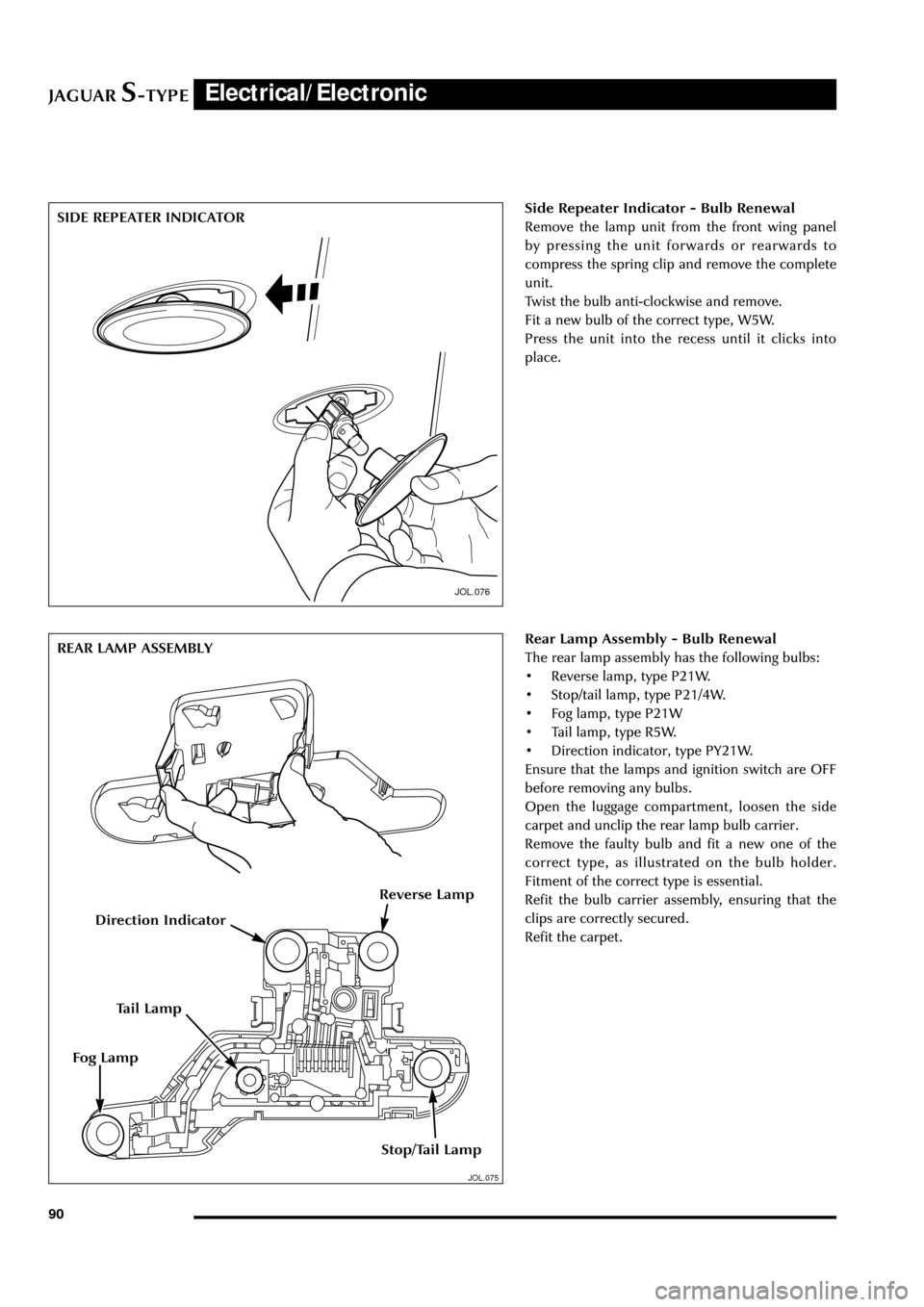
90Side Repeater Indicator - Bulb Renewal
Remove the lamp unit from the front wing panel
by pressing the unit forwards or rearwards to
compress the spring clip and remove the complete
unit.
Twist the bulb anti-clockwise and remove.
Fit a new bulb of the correct type, W5W.
Press the unit into the recess until it clicks into
place.
JOL.076
JOL.075
Rear Lamp Assembly - Bulb Renewal
The rear lamp assembly has the following bulbs:
¥ Reverse lamp, type P21W.
¥ Stop/tail lamp, type P21/4W.
¥ Fog lamp, type P21W
¥ Tail lamp, type R5W.
¥ Direction indicator, type PY21W.
Ensure that the lamps and ignition switch are OFF
before removing any bulbs.
Open the luggage compartment, loosen the side
carpet and unclip the rear lamp bulb carrier.
Remove the faulty bulb and fit a new one of the
correct type, as illustrated on the bulb holder.
Fitment of the correct type is essential.
Refit the bulb carrier assembly, ensuring that the
clips are correctly secured.
Refit the carpet. SIDE REPEATER INDICATOR
REAR LAMP ASSEMBLY
Direction Indicator
Tail Lamp
Stop/Tail Lamp
Fog Lamp
Reverse Lamp
Page 102 of 133
JAGUARS-TYPEElectrical/Electronic
97
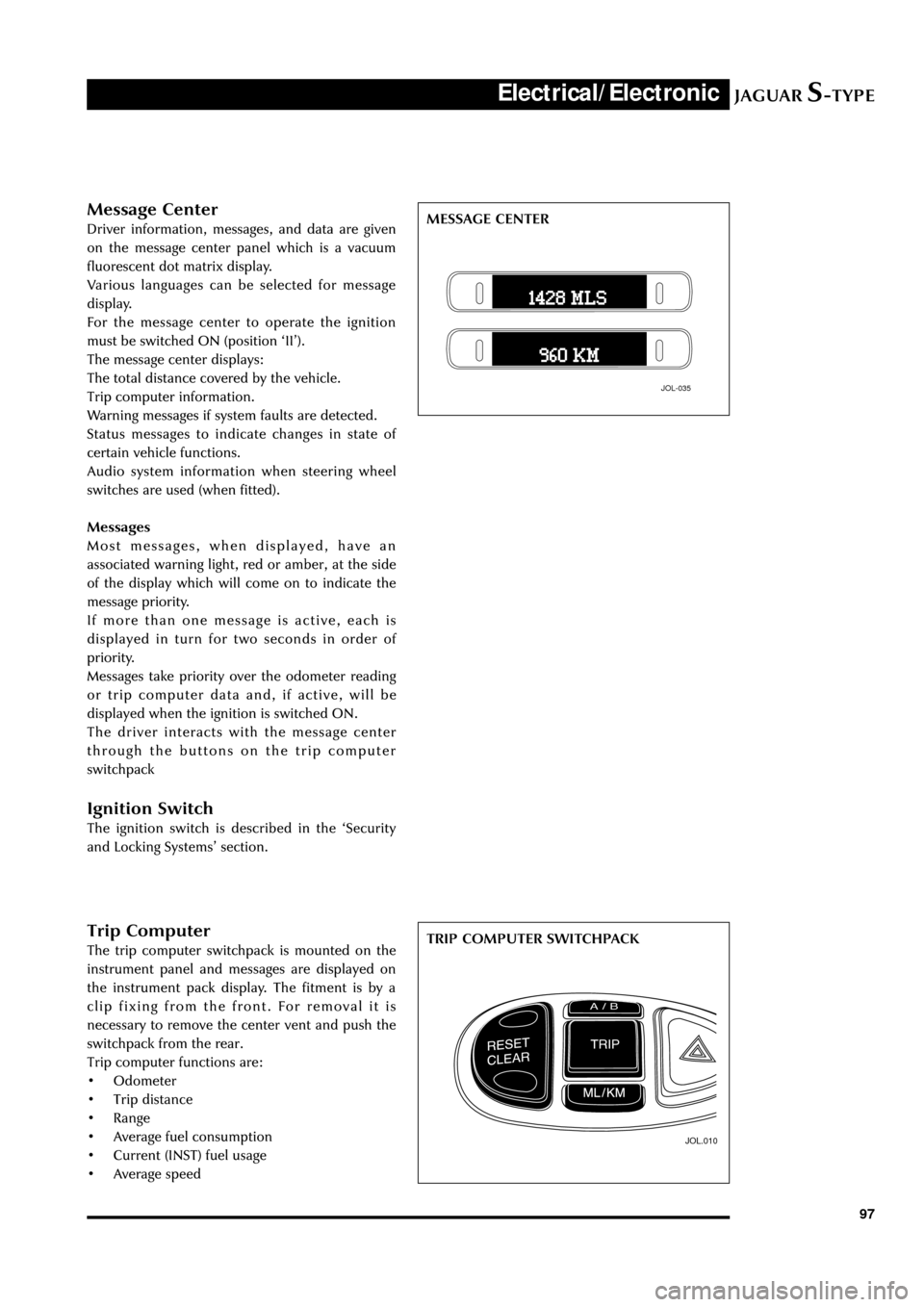
Trip Computer
The trip computer switchpack is mounted on the
instrument panel and messages are displayed on
the instrument pack display. The fitment is by a
clip fixing from the front. For removal it is
necessary to remove the center vent and push the
switchpack from the rear.
Trip computer functions are:
¥ Odometer
¥ Trip distance
¥ Range
¥ Average fuel consumption
¥ Current (INST) fuel usage
¥ Average speed
JOL.010
TRIP COMPUTER SWITCHPACK
Message Center
Driver information, messages, and data are given
on the message center panel which is a vacuum
fluorescent dot matrix display.
Various languages can be selected for message
display.
For the message center to operate the ignition
must be switched ON (position ÔIIÕ).
The message center displays:
The total distance covered by the vehicle.
Trip computer information.
Warning messages if system faults are detected.
Status messages to indicate changes in state of
certain vehicle functions.
Audio system information when steering wheel
switches are used (when fitted).
Messages
Most messages, when displayed, have an
associated warning light, red or amber, at the side
of the display which will come on to indicate the
message priority.
If more than one message is active, each is
displayed in turn for two seconds in order of
priority.
Messages take priority over the odometer reading
or trip computer data and, if active, will be
displayed when the ignition is switched ON.
The driver interacts with the message center
through the buttons on the trip computer
switchpack
Ignition Switch
The ignition switch is described in the ÔSecurity
and Locking SystemsÕ section.
JOL-035
MESSAGE CENTER
Page 112 of 133
JAGUARS-TYPEElectrical/Electronic
107
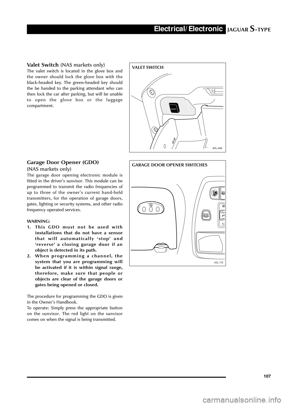
Valet Switch (NAS markets only)
The valet switch is located in the glove box and
the owner should lock the glove box with the
black-headed key. The green-headed key should
the be handed to the parking attendant who can
then lock the car after parking, but will be unable
to open the glove box or the luggage
compartment.
JOL.049
VALET SWITCH
JOL.172
GARAGE DOOR OPENER SWITCHESGarage Door Opener (GDO)
(NAS markets only)
The garage door opening electronic module is
fitted in the driverÕs sunvisor. This module can be
programmed to transmit the radio frequencies of
up to three of the ownerÕs current hand-held
transmitters, for the operation of garage doors,
gates, lighting or security systems, and other radio
frequency operated services.
WARNING:
1. This GDO must not be used with
installations that do not have a sensor
that will automatically ÔstopÕ and
ÔreverseÕ a closing garage door if an
object is detected in its path.
2. When programming a channel, the
system that you are programming will
be activated if it is within signal range,
therefore, make sure that people or
objects are clear of the garage doors or
gates being opened or closed.
The procedure for programming the GDO is given
in the OwnerÕs Handbook.
To operate: Simply press the appropriate button
on the sunvisor. The red light on the sunvisor
comes on when the signal is being transmitted.
JOL.172
Page 113 of 133

JAGUARS-TYPEElectrical/Electronic
108
Security and Locking Systems
Introduction
The following security and locking features are
available but vary by market or options:
¥ Key barrel on driverÕs side only
¥ Encrypted engine immobilization by ignition
key transponder
¥ Radio frequency remote fob
¥ Central locking by key and remote fob
¥ Double locking (not in North America, Japan,
Taiwan)
¥ Drive away door locking
¥ Mechanical child locks on rear doors
¥ Perimeter alarm of doors, bonnet, trunk
¥ Intrusion sensing, ultrasonically sensed (not
in North America, Japan, Taiwan)
¥ Inclination (tilt) sensing (Dealer fit accessory)
¥ Panic alarm, fob operated (certain markets)
¥ Trunk lock isolate (valet lockout, see page
107) - North America only
¥ Electro/mechanical steering column lock
The following convenience features are included
either as standard or optional features:
¥ Remote fob operated driverÕs seat, door
mirrors and steering column memory recall
(two memories)
¥ Remote fob operated trunk lid release
¥ Key operated global close (sliding roof and all
windows)
¥ Key and fob remote-operated global open
(sliding roof and all windows)
¥ Trunk lid and fuel flap interior release buttons
¥ Trunk release button in trunk plinth
¥ Emergency key lock barrel under trunk plinth.
System Description
The security system is controlled by a driver door
control module (DDCM). When activated
unauthorized entry in to the vehicle is detected by
the courtesy lamp switches. When the alarm is
triggered, the system flashes the turn signal lamps
and sounds the alarm system horns.
The passive anti-theft system (PATS) is a feature to
prevent the vehicle being driven away by an
unauthorized person. The PATS system consists of
electronically coded keys, a transceiver and is
controlled by the Instrument Pack. When the
ignition is switched to position ÔIIÕ, the transceiver
energises the ignition key to read its electroniccode that is transmitted back. If the read code
equals a stored code in the control module, the
steering column is unlocked and the powertrain
control module (PCM) will let the engine start.
Otherwise, starting of the engine is disabled
(through the starter disable relay and the PCM).
The security indicator LED provides the driver
with the status of the PATS or security system. If
the security system is armed the light will flash
when the ignition is switched OFF. The PATS light
will illuminate when the key is inserted into the
ignition lock and turned to position ÔIIÕ. It will stay
illuminated until the system has carried out its test
on the key. If the system detects a fault, it will
flash the LED for 1 minute, and then flash out the
corresponding 2 digit fault code.
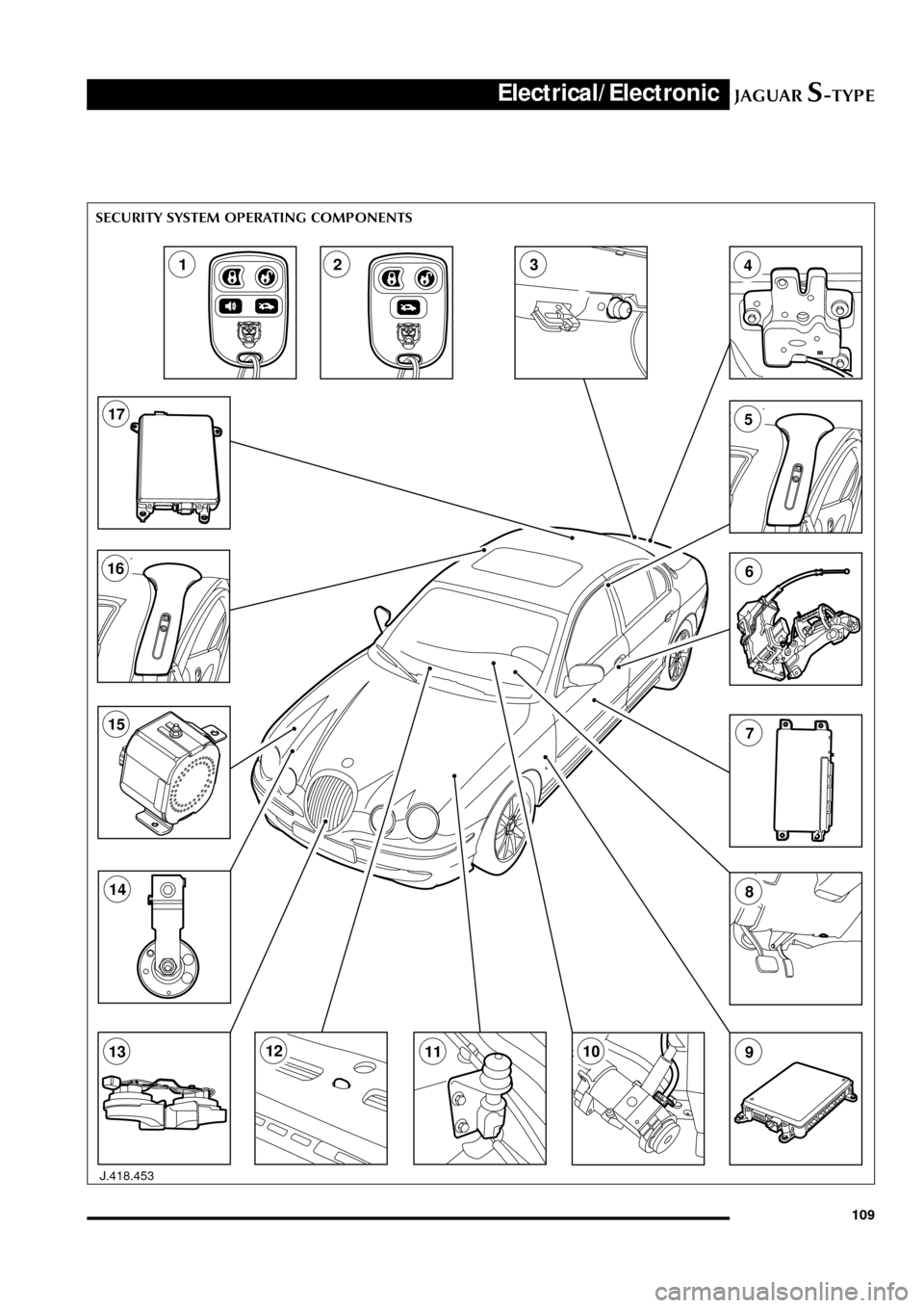
Security System Operating Components
Key to illustration on the following page:
1. Four button transmitter (North America/Rest
of the World)
2. Three button transmitter (Europe/Japan)
3. Trunk release switch
4. Trunk compartment actuator
5. Intrusion sensor
6. Door actuator
7. Driver door control module
8. Data link connector
9. General electronic control module
10. PATS transceiver module
11. Hood switch
12. Security LED
13. Horns
14. Security horn
15. Security sounder
16. Intrusion sensor
17. Rear electronic control module
Page 114 of 133
JAGUARS-TYPEElectrical/Electronic
109
J.418.453
1234
5
6
7
8
910111213
14
15
16
17
SECURITY SYSTEM OPERATING COMPONENTS
Page 115 of 133
JAGUARS-TYPEElectrical/Electronic
110
JOL.145
Vehicle Locking and Unlocking
Door locks and handles
Only the driverÕs door has a key lock.
All doors and the luggage compartment can be
locked and unlocked using a key-ring transmitter.
Keys
Two black-headed keys (and one green-headed
key in the North American market) are supplied
with the vehicle. The key number is recorded on a
plastic tag which is attached to each key.
Each black-headed key will operate the ignition
switch and lock the doors, luggage compartment
and the glove box. The green-headed key is a valetkey which will not unlock a locked glove box or
locked trunk lid. The interior and exterior trunk
switches will not unlock the trunk lid when the
valet switch has been set.
An electronic device is fitted in the head of each
key which is programmed to the vehicle
electronics. When the key is placed in the ignition
switch the vehicle electronics recognize the
correct key and allow engine start. The engine
cannot be started with a key not programmed to
the vehicle electronic systems.
Up to eight keys can be used provided the Dealer
programs them all to the vehicle.
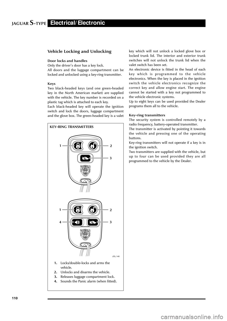
Key-ring transmitters
The security system is controlled remotely by a
radio frequency, battery-operated transmitter.
The transmitter is activated by pointing it towards
the vehicle and pressing one of the operating
buttons.
Key-ring transmitters will not operate if a key is in
the ignition switch.
Two transmitters are supplied with the vehicle, but
up to four can be used provided they are all
programmed to the vehicle by the Dealer.
1
12
2
3
3
4
1.Locks/double-locks and arms the
vehicle.
2.Unlocks and disarms the vehicle.
3.Releases luggage compartment lock.
4.Sounds the Panic alarm (when fitted). KEY-RING TRANSMITTERS