air filter JAGUAR S TYPE 2005 1.G Technical Guide Update
[x] Cancel search | Manufacturer: JAGUAR, Model Year: 2005, Model line: S TYPE, Model: JAGUAR S TYPE 2005 1.GPages: 133, PDF Size: 3.48 MB
Page 21 of 133

JAGUARS-TYPEBody
16
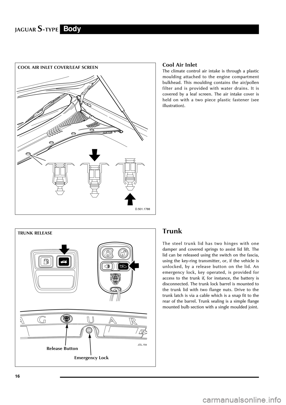
Cool Air Inlet
The climate control air intake is through a plastic
moulding attached to the engine compartment
bulkhead. This moulding contains the air/pollen
filter and is provided with water drains. It is
covered by a leaf screen. The air intake cover is
held on with a two piece plastic fastener (see
illustration).
D.501.1788
Trunk
The steel trunk lid has two hinges with one
damper and covered springs to assist lid lift. The
lid can be released using the switch on the fascia,
using the key-ring transmitter, or, if the vehicle is
unlocked, by a release button on the lid. An
emergency lock, key operated, is provided for
access to the trunk if, for instance, the battery is
disconnected. The trunk lock barrel is mounted to
the trunk lid with two flange nuts. Drive to the
trunk latch is via a cable which is a snap fit to the
rear of the barrel. Trunk sealing is a simple flange
mounted bulb section with a single moulded joint.
JOL.154
TRUNK RELEASE
Release Button
Emergency Lock
COOL AIR INLET COVER/LEAF SCREEN
Page 64 of 133

JAGUARS-TYPEChassis
59
D.211.248
FRONT STEERING ARM requires a Service tool to assist removal. Low-
pressure hose connections are made using
Constant Tension (CT) clamps. Pinion hydraulic
connections are orientated with the bottom
connector low pressure with the longer nut, as
current vehicles.
The PAS fluid is for PAS only; it is not to be used
for transmissions. After manual filling, the system
must be bled using a vacuum pump to remove all
the air from the system to prevent system noises.
Fluid level is checked through a sight window on
the reservoir.
Components replaceable are complete pump,
steering rack, reservoir or hose assembly.
A non-serviceable 10-micron filter is located
within the reservoir to maintain fluid cleanliness
throughout the life of the vehicle. It is essential as
with all Jaguars that the system does not become
contaminated. Cap all ports on disassembly to
prevent contamination ingress. As with current
vehicles, the fluid and reservoir must be renewed
if any major component is replaced i.e. Rack,
pump or cooler.
The road wheels should be set straight ahead and
the steering wheel locked (using service tool
F7LC-3F732-BF) when removal and assembly of
the steering gear or intermediate shaft is required.
This is necessary to prevent damage to the air bag
clock spring within the steering upper column
assembly. The intermediate shaft can only be
assembled to its mating components in one
location. Steering wheel alignment can only be
achieved by adjustment at the tie-rods. A
dimensional check of the steering rack position
may be necessary to verify rack centre.
Steering Column
The steering column assembly is completely new
and uses no parts from previous Jaguar
assemblies:
¥ Construction of the upper column assembly is
based on the use of aluminium extrusions and
castings.
¥ A two shaft lower column assembly is used.
¥ The electronically controlled steering lock, the
steering column lock module (SCLM), is a
physically separate component from the
ignition switch which is fascia mounted.
¥ The dynamic stability control (DSC) steering
wheel position sensor is fitted to the upper
column assembly.
Steering Wheel
The steering wheel consists of a magnesium
armature with a central steel insert. The steering
column and wheel insert are splined with a flat so
that the wheel can only be fitted in one position.
Any misalignment of the steering wheel is
corrected by adjusting the tie rods. The splined
fitting also has a locking taper which requires the
use of a 2 legged puller to remove the wheel.
The steering wheel incorporates the the airbag
module, horn mechanism and the optional cruise
control and audio/phone switches.
Page 68 of 133

JAGUARS-TYPEClimate Control
63
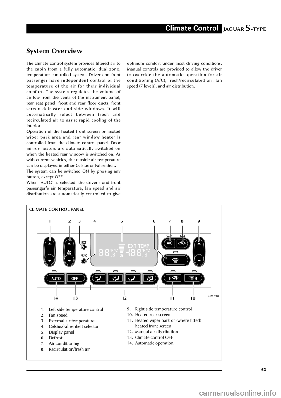
System Overview
The climate control system provides filtered air to
the cabin from a fully automatic, dual zone,
temperature controlled system. Driver and front
passenger have independent control of the
temperature of the air for their individual
comfort. The system regulates the volume of
airflow from the vents of the instrument panel,
rear seat panel, front and rear floor ducts, front
screen defroster and side windows. It will
automatically select between fresh and
recirculated air to assist rapid cooling of the
interior.
Operation of the heated front screen or heated
wiper park area and rear window heater is
controlled from the climate control panel. Door
mirror heaters are automatically switched on
when the heated rear window is switched on. As
with current vehicles, the outside air temperature
can be displayed in either Celsius or Fahrenheit.
The system can be switched ON by pressing any
button, except OFF.
When ÔAUTOÕ is selected, the driverÕs and front
passengerÕs air temperature, fan speed and air
distribution are automatically controlled to give
J.412. 216
1. Left side temperature control
2. Fan speed
3. External air temperature
4. Celsius/Fahrenheit selector
5. Display panel
6. Defrost
7. Air conditioning
8. Recirculation/fresh air9. Right side temperature control
10. Heated rear screen
11. Heated wiper park or (where fitted)
heated front screen
12. Manual air distribution
13. Climate control OFF
14. Automatic operation optimum comfort under most driving conditions.
Manual controls are provided to allow the driver
to override the automatic operation for air
conditioning (A/C), fresh/recirculated air, fan
speed (7 levels), and air distribution.
12 65 4 3
109 8 7
11 13 12 14 CLIMATE CONTROL PANEL
Page 69 of 133

JAGUARS-TYPEClimate Control
64Control Panel
The control panel is a combined unit
incorporating the air conditioning control module
(A/CCM).
Heater/Evaporator and Blower
A single blower, heater and evaporator are fitted
to the passenger side of the vehicle behind the
fascia. Air intake is from the passenger side via
leaf screen slots (see page 16). A particle filter is
mounted forward of the bulkhead in a rain/water
collector box. Mounting of the heater/evaporator
unit and blower assembly is by three bulkhead
fixings and one locator pin.
Condensate drainage is integral with the
heater/evaporator unit and therefore has no
separate drain tubes. The heater matrix is a dual
heater unit with three heater pipes, two inlets of
16mm diameter and one outlet of 19mm
diameter.
D.412.217
Underbonnet Components
Both V6 and V8 engine configurations include a
water valve controlled heating (dual) system and
the valve is mounted behind the right-hand side
headlamp. The V8 engine system, as with current
cars, has a water pump to supplement idle water
flow through the heater and this is mounted on
the right-hand side of the cooling pack. The pump
is held in a mounting rubber, which is pushed
over two pillars on the rear of the fan shroud and
held with two screws.
Condenser
The black-painted aluminium condenser is located
to the front of the combi-cooler and mounts to its
end tanks. The condenser end tubes push into two
grommets, which are in turn held in two steel
brackets, screwed to the radiator end tanks. The
bottom of the condenser is screwed directly into
the radiator tanks. A radiator cooling duct clips
onto the condenser end tanks and also pushes
onto the lower radiator channel. The duct ensures
that all available airflow is directed through the
cooling module.
HEATER/EVAPORATOR AND BLOWER
Blower
Heater/Evaporator
Page 72 of 133

JAGUARS-TYPEClimate Control
67 Pipework
The suction hose and liquid line are a one-piece
assembly. A single screw connects them to the air
conditioning unit manifold at the bulkhead. A
further screw fixing and push-in clip secures them
at the side of the engine bay. The liquid line fixed
to the cooling module then joins with a block
fitting and the suction hose connects with a quick
connect fitting and routes across the underneath
of the cooling module to the compressor. The
compressor suction and discharge hoses are also a
one piece assembly.
A pressure transducer is fitted to the discharge
hose as it connects to the rear of the condenser.
The high side charge port is situated on the
manifold connecting to the receiver drier whilst
the low side is adjacent to the compressor behind
the LH front wheel.
The compressor is a 9Occ scroll, which is variable
from 100% to 30%. Compressor is standard
specification to all vehicles although package
makes them unique to V6 and V8.
Air Distribution
Air distribution is as follows:
¥ Defrost duct integral with the fascia.
¥ Face vents, plenum, manifold, centre face
duct, side face duct, side window demist duct
are all sub-assembled into the fascia.
¥ Driver and front seat passenger foot ducts are
installed in the fascia after it has been fitted
to the vehicle.
¥ Rear foot ducts are fitted to the underframe.
¥ Rear face duct fitted to transmission tunnel.
¥ Rear face vent fitted to console.
¥ Extractor boxes fitted in rear quarter panels.
All flaps are electric servo controlled and
comprise:
¥ Fresh/recirculation - heater/evaporator unit.
¥ Cold air bypass - heater/evaporator unit.
¥ Foot flap - mounted on plenum.
¥ Defrost flap - mounted on plenum.
¥ Face flap - mounted on plenum.
Sensors, for operation of the system, are:
¥ Ambient temperature sensor - located behind
the lower front grille.
¥ Solar sensor - fitted to the top centre of the
fascia at the defrost grille
¥ In-car sensor - aspirated from the plenum
venturi sensor mounted inboard of the
steering column.¥ Two heater air outlet sensors
¥ One evaporator air outlet sensor
Servicing
Routine servicing consists of particle filter
replacement.
Replaceable items on the climate control system
are:
¥ Servo complete with linkages
¥ Sensors
¥ Evaporator and seals
¥ Heater core and seals
¥ Blower motor
¥ Impeller/blower motor wheel
¥ Hoses
¥ Registers/vents
¥ Ducts, except the defrost
¥ Defrost and side window demist grilles
¥ Control unit
¥ Compressor
¥ Water pump
¥ Water valve
¥ Receiver/drier
¥ Condenser
There are no panel diagnostics but PDU facility is
available with extensive capability, similar to
current XJ and XK Series.
System refrigerant is R134a. Vehicle charge weight
is 800 gms and charging is through the high side
charge port only.
Oil type is WSH-MIC231-B and refill quantity is
180 cc -220 cc.
Special tools are hose clamp pliers and air-
conditioning hoses spring lock de-coupler.
General information
Ensure that the grille at the base of the windshield
is kept clear of leaves, snow or other obstructions.
A solar sensor is mounted on top of the fascia, in
the centre of the defrost grille, and this should not
be covered.
The air conditioning system should be run briefly
at least once each week with a cold setting to
prevent the seals from drying out with subsequent
refrigerant leaks.
When the engine and vehicle interior are cold the
fan speed may be low until the engine has warmed
up, this avoids excessively cold air being blown
into the cabin.