steering JAGUAR S TYPE 2005 1.G Technical Guide Update
[x] Cancel search | Manufacturer: JAGUAR, Model Year: 2005, Model line: S TYPE, Model: JAGUAR S TYPE 2005 1.GPages: 133, PDF Size: 3.48 MB
Page 79 of 133

JAGUARS-TYPEElectrical/Electronic
74The SCP communication network will remain
operational even with severing of one of the bus
wires. Communications will also continue if one
of the bus wires is shorted to ground or battery
positive voltage (B+), or if some , but not all,
termination resistors are lost.
Unlike the SCP communication network, the
ISO 9141 communication network will not
function if the wire is shorted to ground or battery
positive voltage (B+). Also, if one of the modules
on the ISO 9141 network loses power or shorts
internally, communication to that module will fail.
Control Modules
The vehicle control module functions are
described briefly below (for further information
refer to the relevant sections throughout the
Guide).
Anti Lock Brake/Traction Control and
Dynamic Stability Control, Control Modules
The anti-lock brake control module is connected
to the SCP communication network. The module
comes in two forms. The first type is the standard
equipped anti-lock brake system (ABS) with
traction control (TC). It controls the brake
pressure to the four wheels to keep the vehicle
under control while braking.
The second type of ABS is optional and is called
dynamic stability control (DSC). This control
module adds yaw sensors to the package to help
in sensing a loss of vehicle control.
Audio Control Unit
The audio control unit is connected to the SCP
communication network and also to the audio
control protocol (ACP) communication network.
The audio control unit communicates with the
compact disc and the cellular phone transceiver.
Driver Door Control Module (DDCM)
DDCM is connected to the SCP communication
network. The module controls many functions
including power windows, driver mirror, power
locks, and keyless remote entry.Driver Seat Control Module (DSCM)
The DSCM is connected to the SCP
communication network. The DSCM is located
under the driver seat and controls the seat
positions. The module also communicates with the
DDCM to control the driver seat memory
functions.
Control Module Locations
Key to illustration on following page:
1.Anti-lock brake system/Traction control
system or Dynamic stability control
(ABS/TCCM or DSCCM)
(non-handed)
2.Throttle actuator control module (TACM)
(non-handed)
3.Powertrain control module (PCM) (handed)
4.Air conditioning control module (A/CCM)
(non-handed)
5.Restraint control module (RCM) (non-handed)
6.Sliding roof control module (SRCM)
(non-handed)
7.Passenger seat heater control module
(PSHCM) (non-handed)
8.Rear electronic control module (RECM)
(non-handed)
9.Vehicle information control module (VICM)
(Japan only)
10.Adaptive damping control module (ADCM)
(non-handed)
11.Parking aid control module (PACM)
(non-handed)
12.Navigation control module (NCM)
(non-handed)
13.Vehicle emergency control module (VECM)
(non-handed)
14.Voice-activated control module (VACM)
(non-handed)
15.Cellular telephone control module (CTCM)
(non-handed)
16.Driver seat heater control module (DSHCM)
(non-handed)
17.Driver seat control module (DSCM) (handed)
18.Driver door control module (DDCM)
(handed)
19.Instrument pack (handed)
20.General electronics control module (GECM)
(non-handed)
21.Steering column lock module (SCLM) (handed)
Page 81 of 133
JAGUARS-TYPEElectrical/Electronic
76Air Conditioning Control Module (A/CCM)
The A/CCM is connected to the SCP
communication network. The A/CCM controls
automatic climate functions that maintain the
vehicle at a constant temperature setting.
Instrument Pack
The instrument pack is connected to the SCP
communication network. The instrument pack
displays information received on the SCP
including speedometer, odometer, fuel, and
message center warnings. The instrument pack
also controls the passive anti-theft system (PATS).
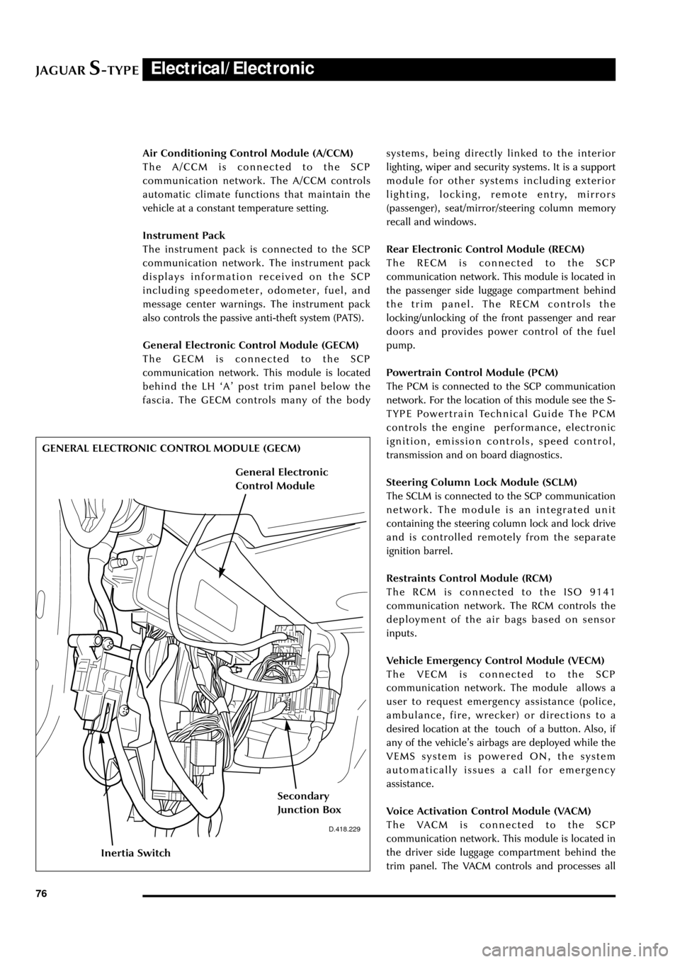
General Electronic Control Module (GECM)
The GECM is connected to the SCP
communication network. This module is located
behind the LH ÔAÕ post trim panel below the
fascia. The GECM controls many of the bodysystems, being directly linked to the interior
lighting, wiper and security systems. It is a support
module for other systems including exterior
lighting, locking, remote entry, mirrors
(passenger), seat/mirror/steering column memory
recall and windows.
Rear Electronic Control Module (RECM)
The RECM is connected to the SCP
communication network. This module is located in
the passenger side luggage compartment behind
the trim panel. The RECM controls the
locking/unlocking of the front passenger and rear
doors and provides power control of the fuel
pump.
Powertrain Control Module (PCM)
The PCM is connected to the SCP communication
network. For the location of this module see the S-
TYPE Powertrain Technical Guide The PCM
controls the engine performance, electronic
ignition, emission controls, speed control,
transmission and on board diagnostics.
Steering Column Lock Module (SCLM)
The SCLM is connected to the SCP communication
network. The module is an integrated unit
containing the steering column lock and lock drive
and is controlled remotely from the separate
ignition barrel.
Restraints Control Module (RCM)
The RCM is connected to the ISO 9141
communication network. The RCM controls the
deployment of the air bags based on sensor
inputs.
Vehicle Emergency Control Module (VECM)
The VECM is connected to the SCP
communication network. The module allows a
user to request emergency assistance (police,
ambulance, fire, wrecker) or directions to a
desired location at the touch of a button. Also, if
any of the vehicleÕs airbags are deployed while the
VEMS system is powered ON, the system
automatically issues a call for emergency
assistance.
Voice Activation Control Module (VACM)
The VACM is connected to the SCP
communication network. This module is located in
the driver side luggage compartment behind the
trim panel. The VACM controls and processes all
D.418.229
GENERAL ELECTRONIC CONTROL MODULE (GECM)
Inertia Switch
Secondary
Junction Box
General Electronic
Control Module
Page 87 of 133

JAGUARS-TYPEElectrical/Electronic
82No Type Rating (amps) Colour Circuit
15 mini 5 Brown Adaptive damping module (ADRC)
16 mini 5 Brown Heated seat switch module,
electrochromic mirror, rain sensor
17 mini 5 Brown RCM, Generator warning lamp
18 mini 20 Yellow Radio, cellular phone, navigation unit
19 mini 15 Blue Steering column motors
20 mini 10 Red GECM, DATC, RECM, Instrument Pack,
brake shift interlock
21 mini 10 Red Power folding mirrors, electric sunblind
22 mini 10 Red DriverÕs door mirror, driverÕs door lock
motor
23 mini 10 Red Right-front high beam
24 mini 5 Brown Passive Anti-Theft System (PATS)
25 mini 10 Red Left-front low beam headlamp
26 - - - Not used
27 mini 10 Red Navigation display, radio, phone,
navigation module, Traffic Master
28 mini 5 Brown Battery-backed security sounder
29 mini 5 Brown Voice control, reversing aid, GECM,
Trailer tow ignition sense, VEMS
30 mini 5 Brown GECM
31 - - - Not used
32 mini 20 Yellow Accessory socket, cigar lighter
33 mini 10 Red GECM illumination power
34 - - - Not used
35 mini 5 Brown Stop lamp switch
Trunk Fusebox
No Type Rating (amps) Colour Circuit
1 mini 15 Blue Luggage compartment release solenoid
2 mini 10 Red Right rear direction indicators, back up,
fog lamps, side markers
3 mini 10 Red Left stop lamp
4 mini 10 Red Fuel door release solenoid
5 mini 10 Red Courtesy and map lamps
6 mini 10 Red Left rear direction indicators, back up,
fog lamps, side markers
7 mini 10 Red Right stop lamp
8 mini 10 Red Center high mounted stop lamp
9 mini 5 Brown Heated mirror
10 mini 5 Brown Traffic Master
11 mini 15 Blue Heated seats
Page 102 of 133
JAGUARS-TYPEElectrical/Electronic
97
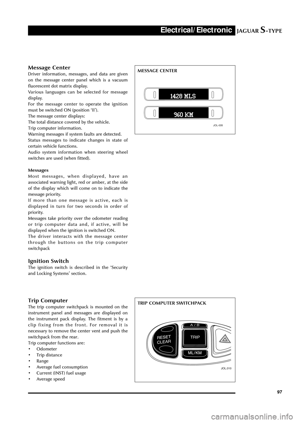
Trip Computer
The trip computer switchpack is mounted on the
instrument panel and messages are displayed on
the instrument pack display. The fitment is by a
clip fixing from the front. For removal it is
necessary to remove the center vent and push the
switchpack from the rear.
Trip computer functions are:
¥ Odometer
¥ Trip distance
¥ Range
¥ Average fuel consumption
¥ Current (INST) fuel usage
¥ Average speed
JOL.010
TRIP COMPUTER SWITCHPACK
Message Center
Driver information, messages, and data are given
on the message center panel which is a vacuum
fluorescent dot matrix display.
Various languages can be selected for message
display.
For the message center to operate the ignition
must be switched ON (position ÔIIÕ).
The message center displays:
The total distance covered by the vehicle.
Trip computer information.
Warning messages if system faults are detected.
Status messages to indicate changes in state of
certain vehicle functions.
Audio system information when steering wheel
switches are used (when fitted).
Messages
Most messages, when displayed, have an
associated warning light, red or amber, at the side
of the display which will come on to indicate the
message priority.
If more than one message is active, each is
displayed in turn for two seconds in order of
priority.
Messages take priority over the odometer reading
or trip computer data and, if active, will be
displayed when the ignition is switched ON.
The driver interacts with the message center
through the buttons on the trip computer
switchpack
Ignition Switch
The ignition switch is described in the ÔSecurity
and Locking SystemsÕ section.
JOL-035
MESSAGE CENTER
Page 103 of 133
JAGUARS-TYPEElectrical/Electronic
98Reset/Clear - Two position rocker switch. Sets the selected trip to zero. Clear can be used to cycle
though: TRIP - ODOMETER - MESSAGES. Clear can hide messages on the message
center.
Mls/Km - Selects metric or imperial data. Also selects languages Those available are:
English, US English, German, Spanish, Italian, French, Dutch, Finnish, Swedish,
Brazilian/Portuguese and Japanese
Trip/Cycle - Successive presses of the switch will display each of the trip data items and the
odometer reading , in turn.
A/B - Selects either A or B trip memory.
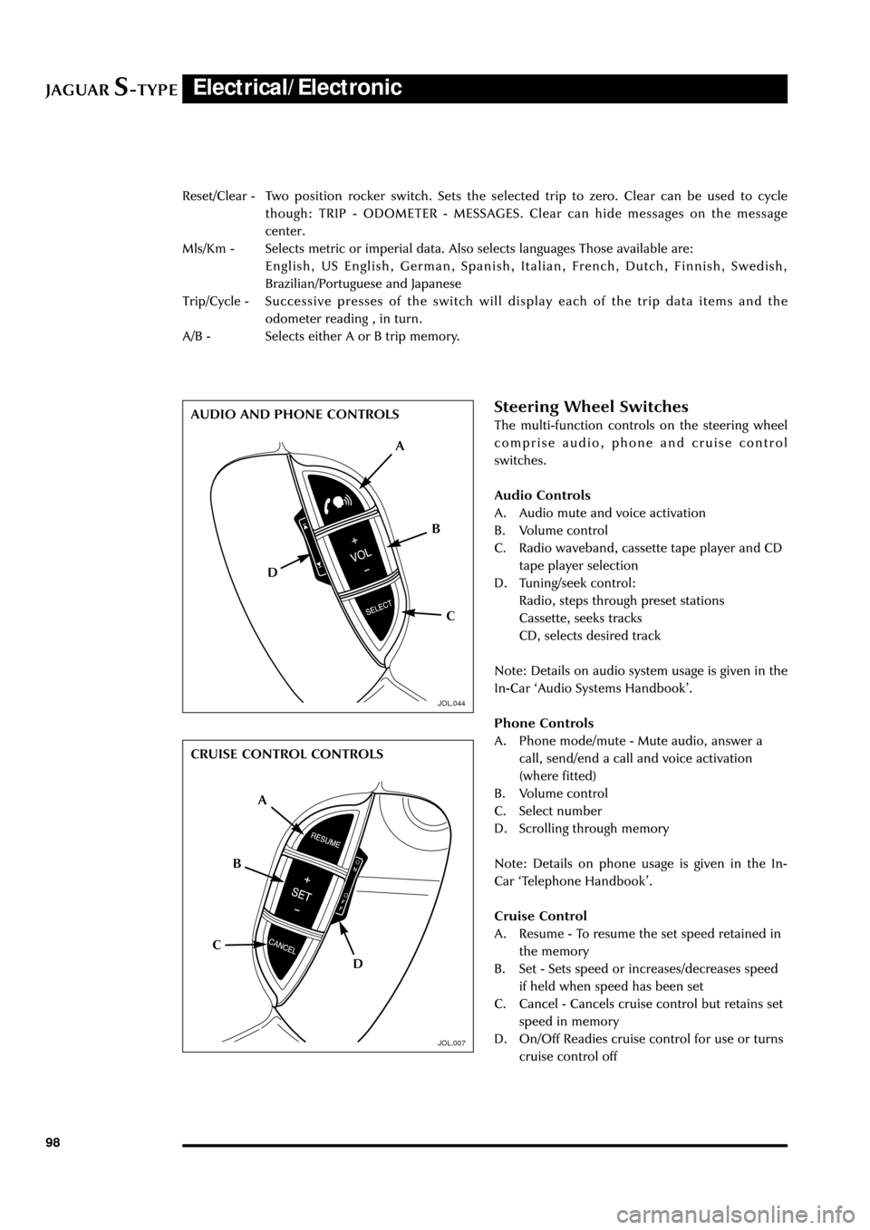
Steering Wheel Switches
The multi-function controls on the steering wheel
comprise audio, phone and cruise control
switches.
Audio Controls
A. Audio mute and voice activation
B. Volume control
C. Radio waveband, cassette tape player and CD
tape player selection
D. Tuning/seek control:
Radio, steps through preset stations
Cassette, seeks tracks
CD, selects desired track
Note: Details on audio system usage is given in the
In-Car ÔAudio Systems HandbookÕ.
Phone Controls
A. Phone mode/mute - Mute audio, answer a
call, send/end a call and voice activation
(where fitted)
B. Volume control
C. Select number
D. Scrolling through memory
Note: Details on phone usage is given in the In-
Car ÔTelephone HandbookÕ.
Cruise Control
A. Resume - To resume the set speed retained in
the memory
B. Set - Sets speed or increases/decreases speed
if held when speed has been set
C. Cancel - Cancels cruise control but retains set
speed in memory
D. On/Off Readies cruise control for use or turns
cruise control off
A
D
C B AUDIO AND PHONE CONTROLS
CRUISE CONTROL CONTROLS
A
D CB
JOL.044
JOL.007
Page 104 of 133
JAGUARS-TYPEElectrical/Electronic
99
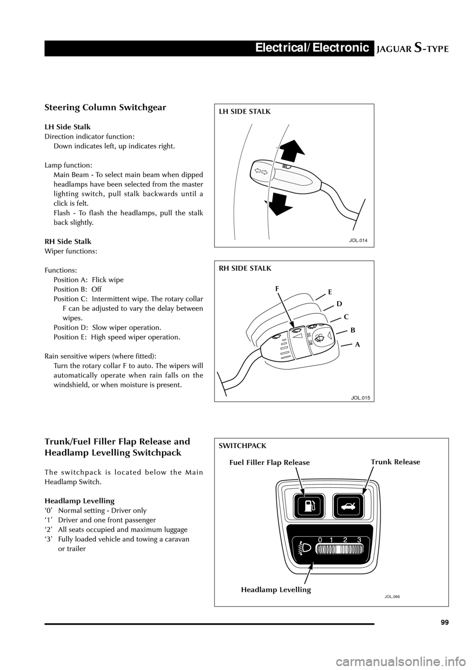
Steering Column Switchgear
LH Side Stalk
Direction indicator function:
Down indicates left, up indicates right.
Lamp function:
Main Beam - To select main beam when dipped
headlamps have been selected from the master
lighting switch, pull stalk backwards until a
click is felt.
Flash - To flash the headlamps, pull the stalk
back slightly.
RH Side Stalk
Wiper functions:
Functions:
Position A: Flick wipe
Position B: Off
Position C: Intermittent wipe. The rotary collar
F can be adjusted to vary the delay between
wipes.
Position D: Slow wiper operation.
Position E: High speed wiper operation.
Rain sensitive wipers (where fitted):
Turn the rotary collar F to auto. The wipers will
automatically operate when rain falls on the
windshield, or when moisture is present.
JOL.014
JOL.015
Trunk/Fuel Filler Flap Release and
Headlamp Levelling Switchpack
The switchpack is located below the Main
Headlamp Switch.
Headlamp Levelling
Ô0Õ Normal setting - Driver only
Ô1Õ Driver and one front passenger
Ô2Õ All seats occupied and maximum luggage
Ô3Õ Fully loaded vehicle and towing a caravan
or trailer
JOL.066
Trunk ReleaseFuel Filler Flap Release
Headlamp Levelling
LH SIDE STALK
RH SIDE STALK
A F
E
D
C
B
SWITCHPACK
Page 108 of 133
JAGUARS-TYPEElectrical/Electronic
103 Note: If the switches are held for longer than six
seconds, e.g. when attempting to overcome frozen
or jammed windows, the window drive will be
switched off for a few seconds to protect the
window drive motors.
Memory Setting (where fitted)
The position of the driverÕs seat, steering column
and exterior rear view mirrors can be memorized
and recalled. Two different driving position
profiles can be entered In the memory. The
switches for seat, mirror, steering column
adjustment and memory setting can be operated
with or without the key being in the ignition.
To store a driving position in the memory:
1. Adjust the seat, steering column an exterior
rear view mirrors to the desired position.
2. Push the memory button and the light in the
switch will illuminate
3. Within five seconds, push button Ô1Õ orÕ2Õ to
memorize the configuration. The memory
button light will go out and a chime will
indicate that the setting procedure is
complete. Additionally, if the ignition is on,
the message center will display a message
that the settings have been saved.
To recall a memorized position, the gear selector
lever must be in ÔPÕ or ÔNÕ on automatic
transmission vehicles and the park brake must be
applied on manual transmission vehicles. Press
and release the appropriate memory button (Ô1Õ or
Ô2Õ). The seat, steering column and door mirrors
will move automatically to the memorized
position.
The key ring transmitter can also be set to
memorize the position of the driverÕs seat,
steering column and exterior rear view mirrors.
Memory Recall Using a Key-ring Transmitter
The key-ring transmitter will recall a memory
position when the unlock button is pressed when
set as follows:
Adjust the seat, steering column and exterior rear
view mirrors to the desired position.
Press ÔmemoryÕ button.
Within five seconds, press any button on the key-
ring transmitter.
Press button Ô1Õ or Ô2Õ.
Repeat for the other transmitter, pressing the
remaining memory button.
To cancel key-ring transmitter memory recall:
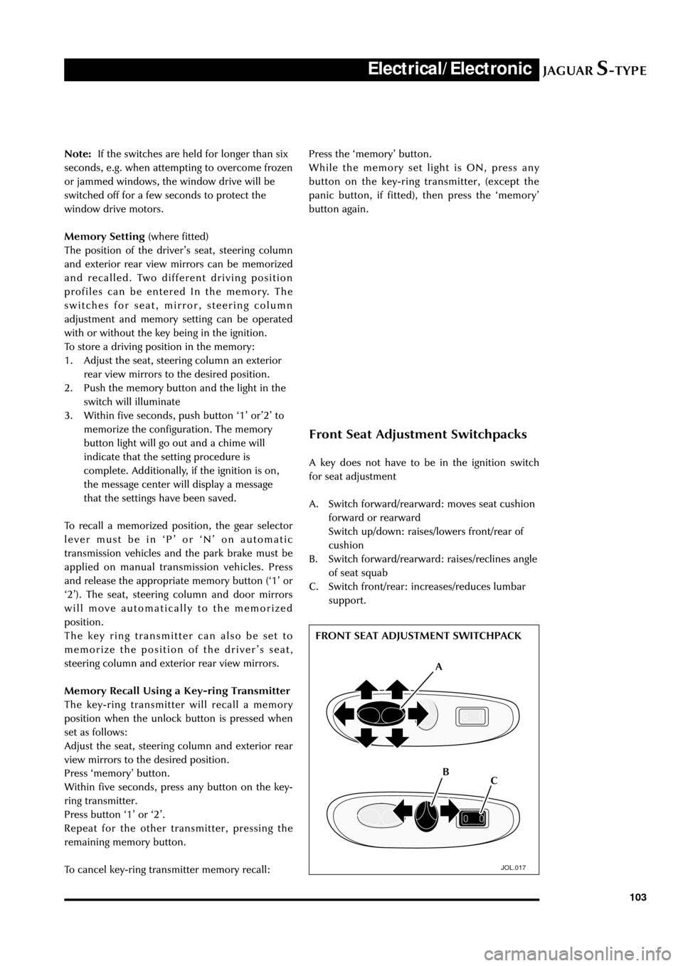
Front Seat Adjustment Switchpacks
A key does not have to be in the ignition switch
for seat adjustment
A. Switch forward/rearward: moves seat cushion
forward or rearward
Switch up/down: raises/lowers front/rear of
cushion
B. Switch forward/rearward: raises/reclines angle
of seat squab
C. Switch front/rear: increases/reduces lumbar
support.
JOL.017
FRONT SEAT ADJUSTMENT SWITCHPACK
A
C B Press the ÔmemoryÕ button.
While the memory set light is ON, press any
button on the key-ring transmitter, (except the
panic button, if fitted), then press the ÔmemoryÕ
button again.
Page 111 of 133
JAGUARS-TYPEElectrical/Electronic
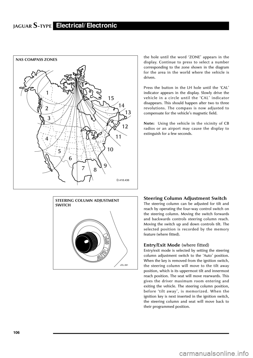
106the hole until the word ÔZONEÕ appears in the
display. Continue to press to select a number
corresponding to the zone shown in the diagram
for the area in the world where the vehicle is
driven.
Press the button in the LH hole until the ÔCALÕ
indicator appears in the display. Slowly drive the
vehicle in a circle until the ÔCALÕ indicator
disappears. This should happen after two to three
revolutions. The compass is now adjusted to
compensate for the vehicleÕs magnetic field.
Note:Using the vehicle in the vicinity of CB
radios or an airport may cause the display to
extinguish for a few seconds.
D.418.436
JOL.061
STEERING COLUMN ADJUSTMENT
SWITCH NAS COMPASS ZONESSteering Column Adjustment Switch
The steering column can be adjusted for tilt and
reach by operating the four-way control switch on
the steering column. Moving the switch forwards
and backwards controls steering column reach.
Moving the switch up and down controls tilt. The
selected position is recorded by the memory
feature (where fitted).
Entry/Exit Mode (where fitted)
Entry/exit mode is selected by setting the steering
column adjustment switch to the ÔAutoÕ position.
When the key is removed from the ignition switch,
the steering column will move to the tilt away
position, which is its uppermost tilt and innermost
reach position. The seat will move rearwards. This
gives the driver maximum room entering and
exiting the vehicle. The steering column position,
before Ôtilt awayÕ, is memorized. When the
ignition key is next inserted in the ignition switch,
the steering column and seat will move back to
their programmed position.
Page 113 of 133

JAGUARS-TYPEElectrical/Electronic
108
Security and Locking Systems
Introduction
The following security and locking features are
available but vary by market or options:
¥ Key barrel on driverÕs side only
¥ Encrypted engine immobilization by ignition
key transponder
¥ Radio frequency remote fob
¥ Central locking by key and remote fob
¥ Double locking (not in North America, Japan,
Taiwan)
¥ Drive away door locking
¥ Mechanical child locks on rear doors
¥ Perimeter alarm of doors, bonnet, trunk
¥ Intrusion sensing, ultrasonically sensed (not
in North America, Japan, Taiwan)
¥ Inclination (tilt) sensing (Dealer fit accessory)
¥ Panic alarm, fob operated (certain markets)
¥ Trunk lock isolate (valet lockout, see page
107) - North America only
¥ Electro/mechanical steering column lock
The following convenience features are included
either as standard or optional features:
¥ Remote fob operated driverÕs seat, door
mirrors and steering column memory recall
(two memories)
¥ Remote fob operated trunk lid release
¥ Key operated global close (sliding roof and all
windows)
¥ Key and fob remote-operated global open
(sliding roof and all windows)
¥ Trunk lid and fuel flap interior release buttons
¥ Trunk release button in trunk plinth
¥ Emergency key lock barrel under trunk plinth.
System Description
The security system is controlled by a driver door
control module (DDCM). When activated
unauthorized entry in to the vehicle is detected by
the courtesy lamp switches. When the alarm is
triggered, the system flashes the turn signal lamps
and sounds the alarm system horns.
The passive anti-theft system (PATS) is a feature to
prevent the vehicle being driven away by an
unauthorized person. The PATS system consists of
electronically coded keys, a transceiver and is
controlled by the Instrument Pack. When the
ignition is switched to position ÔIIÕ, the transceiver
energises the ignition key to read its electroniccode that is transmitted back. If the read code
equals a stored code in the control module, the
steering column is unlocked and the powertrain
control module (PCM) will let the engine start.
Otherwise, starting of the engine is disabled
(through the starter disable relay and the PCM).
The security indicator LED provides the driver
with the status of the PATS or security system. If
the security system is armed the light will flash
when the ignition is switched OFF. The PATS light
will illuminate when the key is inserted into the
ignition lock and turned to position ÔIIÕ. It will stay
illuminated until the system has carried out its test
on the key. If the system detects a fault, it will
flash the LED for 1 minute, and then flash out the
corresponding 2 digit fault code.
Security System Operating Components
Key to illustration on the following page:
1. Four button transmitter (North America/Rest
of the World)
2. Three button transmitter (Europe/Japan)
3. Trunk release switch
4. Trunk compartment actuator
5. Intrusion sensor
6. Door actuator
7. Driver door control module
8. Data link connector
9. General electronic control module
10. PATS transceiver module
11. Hood switch
12. Security LED
13. Horns
14. Security horn
15. Security sounder
16. Intrusion sensor
17. Rear electronic control module
Page 116 of 133
JAGUARS-TYPEElectrical/Electronic
111 Steering Column Lock
The steering column lock is remote from the
ignition switch and controlled electronically.
When the ignition key is removed from the
ignition switch the steering column lock is
engaged. The lock is disengaged when the key is
placed in the ignition switch.
The lock can be clearly heard as it engages and
disengages.
In rare circumstances it may be necessary to
gently turn the steering wheel from side to side to
release the steering column lock.
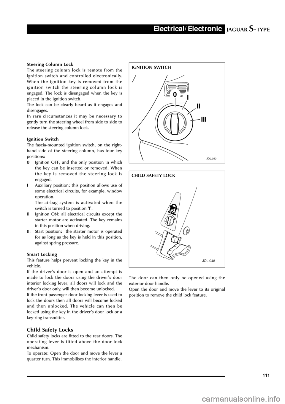
Ignition Switch
The fascia-mounted ignition switch, on the right-
hand side of the steering column, has four key
positions:
0Ignition OFF, and the only position in which
the key can be inserted or removed. When
the key is removed the steering lock is
engaged.
IAuxiliary position: this position allows use of
some electrical circuits, for example, window
operation.
The airbag system is activated when the
switch is turned to position ÔIÕ.
II Ignition ON: all electrical circuits except the
starter motor are activated. The key remains
in this position when driving.
III Start position: the starter motor is operated
for as long as the key is held in this position,
against spring pressure.
Smart Locking
This feature helps prevent locking the key in the
vehicle.
If the driverÕs door is open and an attempt is
made to lock the doors using the driverÕs door
interior locking lever, all doors will lock and the
driverÕs door only, will then become unlocked.
If the front passenger door locking lever is used to
lock the doors then all doors will become locked
and then unlocked. The vehicle can then be
locked using the key in the driverÕs door lock or a
key-ring transmitter.
Child Safety Locks
Child safety locks are fitted to the rear doors. The
operating lever is fitted above the door lock
mechanism.
To operate: Open the door and move the lever a
quarter turn. This immobilises the interior handle.
JOL.050
IGNITION SWITCH
JOL.048
The door can then only be opened using the
exterior door handle.
Open the door and move the lever to its original
position to remove the child lock feature.CHILD SAFETY LOCK