length JAGUAR S TYPE 2005 1.G Technical Guide Update
[x] Cancel search | Manufacturer: JAGUAR, Model Year: 2005, Model line: S TYPE, Model: JAGUAR S TYPE 2005 1.GPages: 133, PDF Size: 3.48 MB
Page 19 of 133
JAGUARS-TYPEBody
14
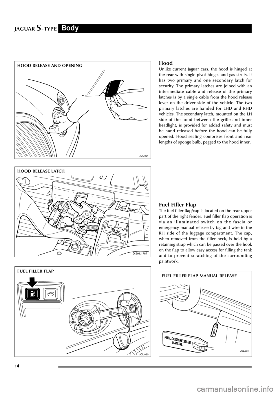
Hood
Unlike current Jaguar cars, the hood is hinged at
the rear with single pivot hinges and gas struts. It
has two primary and one secondary latch for
security. The primary latches are joined with an
intermediate cable and release of the primary
latches is by a single cable from the hood release
lever on the driver side of the vehicle. The two
primary latches are handed for LHD and RHD
vehicles. The secondary latch, mounted on the LH
side of the hood between the grille and inner
headlight, is provided for added safety and must
be hand released before the hood can be fully
opened. Hood sealing comprises front and rear
lengths of sponge bulb, pegged to the hood inner.
JOL.091
HOOD RELEASE AND OPENING
JOL.091
JOL.030
FUEL FILLER FLAP
JOL.031
FUEL FILLER FLAP MANUAL RELEASE
Fuel Filler Flap
The fuel filler flap/cap is located on the rear upper
part of the right fender. Fuel filler flap operation is
via an illuminated switch on the fascia or
emergency manual release by tag and wire in the
RH side of the luggage compartment. The cap,
when removed from the filler neck, is held by a
retaining strap which can be passed over the hook
on the flap to allow easy access for filling the tank
and to prevent scratching of the surrounding
paintwork.
D.501.1787
HOOD RELEASE LATCH
Page 38 of 133
JAGUARS-TYPEOccupant Protection
33
Airbags
Driver Airbag
The driver airbag module is fitted in the centre of
the steering wheel and is of conventional design.
A reduced charge propellant (Ôde-poweredÕ) is
used to minimise impact effects where the driver
is seated close to the wheel.
The module is secured by two side screws on the
left and right underside of the steering wheel.
Passenger Airbag
WARNING:
Do not place objects on the passenger airbag
deployment panel. Injury could occur if the
airbag contacts an object during inflation.
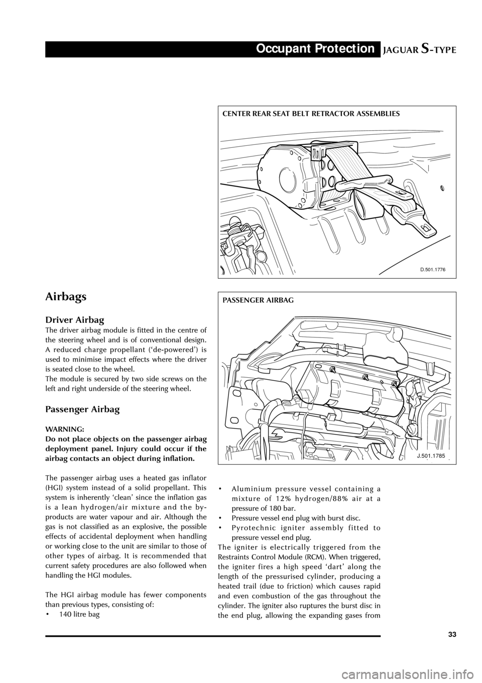
The passenger airbag uses a heated gas inflator
(HGI) system instead of a solid propellant. This
system is inherently ÔcleanÕ since the inflation gas
is a lean hydrogen/air mixture and the by-
products are water vapour and air. Although the
gas is not classified as an explosive, the possible
effects of accidental deployment when handling
or working close to the unit are similar to those of
other types of airbag. It is recommended that
current safety procedures are also followed when
handling the HGI modules.
The HGI airbag module has fewer components
than previous types, consisting of:
¥ 140 litre bag
D.501.1776
CENTER REAR SEAT BELT RETRACTOR ASSEMBLIES
J.501.1785
PASSENGER AIRBAG
¥ Aluminium pressure vessel containing a
mixture of 12% hydrogen/88% air at a
pressure of 180 bar.
¥ Pressure vessel end plug with burst disc.
¥ Pyrotechnic igniter assembly fitted to
pressure vessel end plug.
The igniter is electrically triggered from the
Restraints Control Module (RCM). When triggered,
the igniter fires a high speed ÔdartÕ along the
length of the pressurised cylinder, producing a
heated trail (due to friction) which causes rapid
and even combustion of the gas throughout the
cylinder. The igniter also ruptures the burst disc in
the end plug, allowing the expanding gases from
Page 39 of 133
JAGUARS-TYPEOccupant Protection
34
D.501.1474
SIDE AIRBAGS the pressure vessel to inflate the airbag. The
airbag is a top mounted assembly and deploys in
an upwards direction, climbing the windshield
before folding downwards. After deployment, the
bag deflates through two vents.
The airbag deployment door is an integral part of
the top fascia moulding. The airbag module is
bolted to the underside of the fascia via a steel
deployment chute and is also bolted to two
brackets on the tubular cross car beam which
supports the fascia assembly.
Note:The module is not handed. To access the
airbag module, the complete fascia assembly must
be removed.
Side Airbag
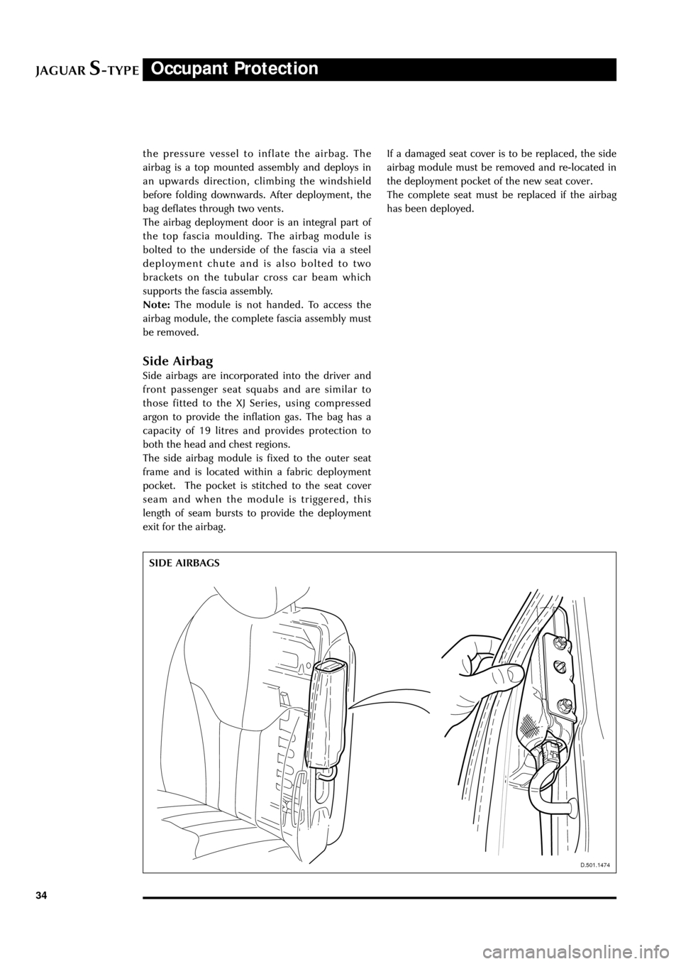
Side airbags are incorporated into the driver and
front passenger seat squabs and are similar to
those fitted to the XJ Series, using compressed
argon to provide the inflation gas. The bag has a
capacity of 19 litres and provides protection to
both the head and chest regions.
The side airbag module is fixed to the outer seat
frame and is located within a fabric deployment
pocket. The pocket is stitched to the seat cover
seam and when the module is triggered, this
length of seam bursts to provide the deployment
exit for the airbag.
D.501.1474
If a damaged seat cover is to be replaced, the side
airbag module must be removed and re-located in
the deployment pocket of the new seat cover.
The complete seat must be replaced if the airbag
has been deployed.
Page 52 of 133
JAGUARS-TYPEChassis
47
Front Suspension
The independent front wheel suspension is a
double wishbone axle arrangement with
aluminium control arms. The two arms are of
different lengths, which minimises the changes in
track and camber. Inclination of the upper control
arm axis provides anti-dive front suspension
action. There are two front cross members,
known as Number 1 and Number 2.
Number 1, the forward cross member, is a steel
fabrication, non-isolated, which locates the lower
control arm front mounting, the anti-roll bar and
the cooling module.
The rear cross member, Number 2, is an
aluminium casting, non-isolated and it locates the
lower control arm rear mounting, the power
steering rack and the engine hydro-mounts.
WARNING: No attempt must be made to
weld or repair the aluminium cross
member. If it is damaged, a new one must
be installed.
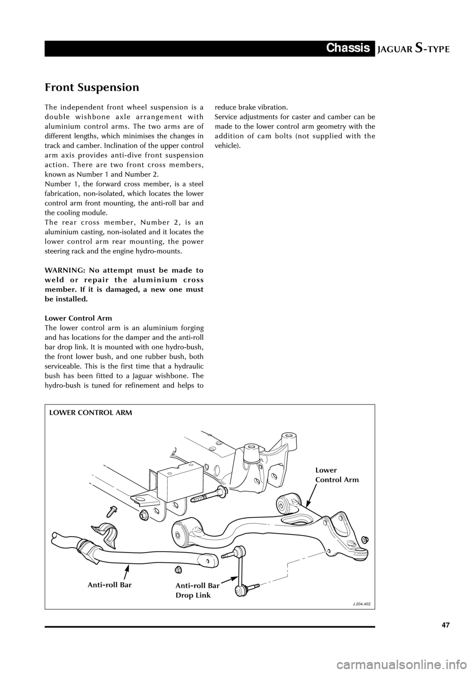
Lower Control Arm
The lower control arm is an aluminium forging
and has locations for the damper and the anti-roll
bar drop link. It is mounted with one hydro-bush,
the front lower bush, and one rubber bush, both
serviceable. This is the first time that a hydraulic
bush has been fitted to a Jaguar wishbone. The
hydro-bush is tuned for refinement and helps to
J.204.402
reduce brake vibration.
Service adjustments for caster and camber can be
made to the lower control arm geometry with the
addition of cam bolts (not supplied with the
vehicle).
LOWER CONTROL ARM
J.204.402
Lower
Control Arm
Anti-roll BarAnti-roll Bar
Drop Link
Page 59 of 133
JAGUARS-TYPEChassis
54The centre joint is a conventional hookes joint
with staked lugs and the rubber flex couplings
have spigoted sleeves to the transmission and rear
axle final drive unit (three bolt fixings)
All driveshafts are balanced. If undercoating the
vehicle, protect the driveshaft, universal joints
and the axleshafts to prevent overspray of the
undercoating material.
Driveshaft weight is:
¥ V6 auto 12.7 kg
¥ V8 auto 13.4 kg
¥ V6 manual 14.1 kg
Serviceable parts are the centre bearing, flex
coupling, rubber boot, alignment bearing and
fasteners. Lubrication of the driveshaft
components is unnecessary. The universal joint is
equipped with nylon thrust washers, located at
the base of the bearing cup.
Balancing of the driveshaft is achieved using a
PDU with the new vibration analyser. This gives
details of where the shaft is out of balance and by
how much and where to place the balance nuts.
Final Drive (differential)
The final drive, differential, has a steel case and
rear cover, no drain plug and has a sealed for life
lubricant. Differential weight is 27 kilograms and
oil capacity 1.5 litres of synthetic oil (M2C192A).
The hypoid gearset is mounted in taper roller
bearings. It has a two point differential assembly
retained by bearing straps. The central pinion is
on the body centreline. Pinion and output oil
seals, the companion flange and nut and the
needle roller output bearing are the only
serviceable items.
Final drive ratios are:
3.31:1 (V6 and V8 auto)
2.87:1 (V6 manual)
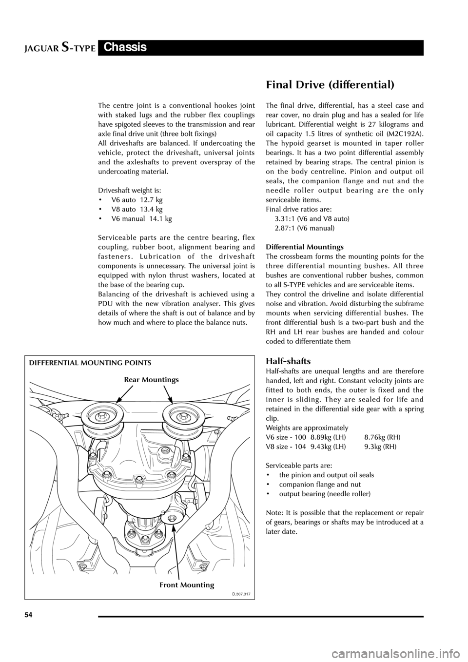
Differential Mountings
The crossbeam forms the mounting points for the
three differential mounting bushes. All three
bushes are conventional rubber bushes, common
to all S-TYPE vehicles and are serviceable items.
They control the driveline and isolate differential
noise and vibration. Avoid disturbing the subframe
mounts when servicing differential bushes. The
front differential bush is a two-part bush and the
RH and LH rear bushes are handed and colour
coded to differentiate them
Half-shafts
Half-shafts are unequal lengths and are therefore
handed, left and right. Constant velocity joints are
fitted to both ends, the outer is fixed and the
inner is sliding. They are sealed for life and
retained in the differential side gear with a spring
clip.
Weights are approximately
V6 size - 100 8.89kg (LH) 8.76kg (RH)
V8 size - 104 9.43kg (LH) 9.3kg (RH)
Serviceable parts are:
¥ the pinion and output oil seals
¥ companion flange and nut
¥ output bearing (needle roller)
Note: It is possible that the replacement or repair
of gears, bearings or shafts may be introduced at a
later date.
D.307.317
DIFFERENTIAL MOUNTING POINTS
D.307.317
Front Mounting
Rear Mountings