power steering JAGUAR S TYPE 2005 1.G Technical Guide Update
[x] Cancel search | Manufacturer: JAGUAR, Model Year: 2005, Model line: S TYPE, Model: JAGUAR S TYPE 2005 1.GPages: 133, PDF Size: 3.48 MB
Page 6 of 133

Contents
1
Subject Page
Glossary
Abbreviations 3
Introduction4
Vehicle Weights 5
Dimensions 5
Vehicle Features 6
Body
Body Structure 10
Engine Compartment 15
Trunk 16
Jacking and Towing 18
Glazing 19
Doors and Door Mirrors 21
Windshield Wipers and Washers 23
Exterior and Interior Trim 24
Seats 26
Interior Features 30
Occupant Protection
Seat Belts 32
Airbags 33
SRS Operation 35
Fuel System
Introduction 38
Evaporative Emissions System 42
Exhaust System
Introduction 44
Transmission
Introduction 45
Chassis
Introduction 46
Front Suspension 47
Rear Suspension 49
Wheels and Tyres 52
Driveline 53
Final Drive (differential) 54
Brakes 55
Power Assisted Steering 58
Steering Column 59
Climate Control
System Overview 63
continued:
JAGUARS-TYPE
Page 8 of 133

JAGUARS-TYPEGlossary
3 A Ab
bb
br
re
ev
vi
ia
at
ti
io
on
nD
De
es
sc
cr
ri
ip
pt
ti
io
on
n
ABS anti-lock braking system
ABS/TCCM anti-lock braking system/
traction control system control
module
A/C air conditioning
A/CCM air conditioning control
module
ADCM adaptive damping control
module
ADRC adaptive damper ride control
ALR automatic locking retractor
BIW body-in-white
ûC degree Celsius
CAN controller area network
CATS computer active technology
suspension
CD compact disc
CTCM cellular telephone control
module
DATC dual automatic temperature
control
DDCM driver door control module
DSC(CM) dynamic stability control
(control module)
DSCM driver seat control module
DSHCM driver seat heater control
module
ECM electronic control module
EFT engine fuel temperature
(sensor)
EVAP evaporative emission
FTP fuel tank pressure (sensor)
GDO garage door opener
GECM general electronic control
module
GPS global positioning system
HO2S heated oxygen sensor
in inch
IP injection pressure (sensor)
IVD interactive vehicle dynamics
kg kilogram
km/h kilometer per hour
kW kilowatt
lb pound
m meter The following abbreviations are used in this document:
A Ab
bb
br
re
ev
vi
ia
at
ti
io
on
nD
De
es
sc
cr
ri
ip
pt
ti
io
on
n
LH(D) left-hand (drive)
mile/h mile per hour
mm millimeter
ms millisecond
NAS North American specification
NCM navigation control module
Nm Newton meter
OBD on-board diagnostics
PAS power assisted steering
PATS passive anti-theft system
PCM powertrain control module
PDU portable diagnostic unit
PSHCM passenger seat heater control
module
RECM rear electronic control module
RCM restraints control module
RH(D) right-hand (drive)
RPC(M) reverse park control (module)
RTTI real time traffic information
SAE Society of Automotive Engineers
SCLM steering column lock module
SCP standard corporate protocol
SRCM sliding roof control module
SRS supplementary restraints
system
TACM throttle actuator control
module
UK United Kingdom
USA United States of America
V volt
VACM voice-activated control module
VECM vehicle emergency control
module
VEMS vehicle emergency messaging
system
VICM vehicle information control
module
VICS vehicle information and
communication system
VIN vehicle identification number
Page 9 of 133
JAGUARS-TYPE
4
Introduction
The Jaguar S-TYPE is an all-new, luxury sports sedan with a distinctive style, refined power, agile
handling, supple ride and luxurious comfort.
Powertrains are a V8 (AJ28) petrol engine, derived from the engines currently used in XJ and XK Series
vehicles, with a new five-speed automatic transmission or alternatively, a V6 (AJ-V6) petrol engine
coupled with either a five-speed automatic transmission or a five-speed manual transmission. The new
V6 engine and transmission units and the updated variations to the V8 engine are described in the
ÔJaguar S-TYPE Powertrain IntroductionÕ Technical Guide, which compliments this Guide.
As with current vehicles, variable rate steering control is fitted and all vehicles have ABS brakes with
traction control as standard. A new, optional feature with the Jaguar S-TYPE is Dynamic Stability Control
(DSC), yaw control, which assists the driver in maintaining directional control of the vehicle.
Unlike current vehicles, the hood is hinged at its rear with a safety catch provided at the front of the
hood. A tilt and slide sliding roof with a sunshade is an optional feature.
Both front seats have electrically operated 8-way adjustments as standard and memory equipment is
available as an option. To allow a greater load to be carried in the luggage compartment, the rear seats
can be folded forwards and are split in a 60/40 configuration.
Automatic climate control, with dual temperature control for the driver and front passenger, is a
standard feature on all vehicles. Another new item is reverse park control, a system giving the driver
audible warning of obstructions which could damage the vehicle during reversing.
A standard fit radio/cassette unit provides in-car entertainment with a CD autochanger also being
offered. Other options include a phone, navigation system, vehicle emergency monitoring system and
certain voice activated systems. Optional cruise control and audio switches are fitted to the steering
wheel. All vehicles have a trip computer system and a message center.
Security features are immobiliser and alarm. Optional features include intruder sensor and inclination
sensor. The 3 or 4 button key-ring transmitter has radio frequency operation with an encrypted rolling
code to help prevent theft of the vehicle.
Standard Corporate Protocol (SCP) is the only computer system highway for all the vehicle electronic
controls, CAN is not used.
Page 11 of 133
JAGUARS-TYPEIntroduction
6
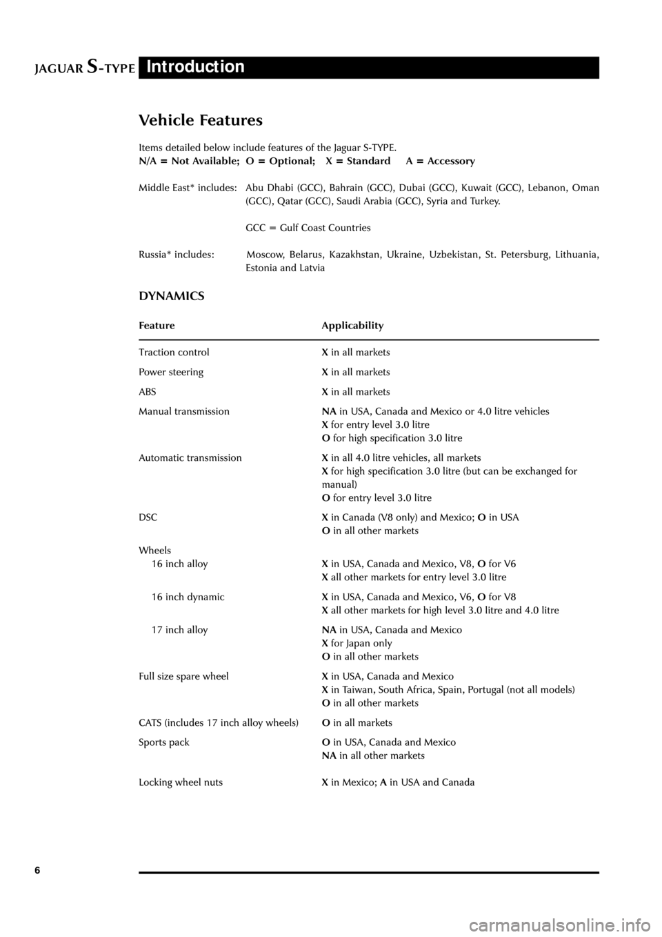
Items detailed below include features of the Jaguar S-TYPE.
N/A = Not Available; O = Optional; X = Standard A = Accessory
Middle East* includes: Abu Dhabi (GCC), Bahrain (GCC), Dubai (GCC), Kuwait (GCC), Lebanon, Oman
(GCC), Qatar (GCC), Saudi Arabia (GCC), Syria and Turkey.
GCC = Gulf Coast Countries
Russia* includes: Moscow, Belarus, Kazakhstan, Ukraine, Uzbekistan, St. Petersburg, Lithuania,
Estonia and Latvia
DYNAMICS
Feature Applicability
Traction controlXin all markets
Power steeringXin all markets
ABSXin all markets
Manual transmissionNAin USA, Canada and Mexico or 4.0 litre vehicles
Xfor entry level 3.0 litre
Ofor high specification 3.0 litre
Automatic transmissionXin all 4.0 litre vehicles, all markets
Xfor high specification 3.0 litre (but can be exchanged for
manual)
Ofor entry level 3.0 litre
DSCXin Canada (V8 only) and Mexico; Oin USA
Oin all other markets
Wheels
16 inch alloyXin USA, Canada and Mexico, V8, Ofor V6
Xall other markets for entry level 3.0 litre
16 inch dynamicXin USA, Canada and Mexico, V6, Ofor V8
Xall other markets for high level 3.0 litre and 4.0 litre
17 inch alloyNAin USA, Canada and Mexico
Xfor Japan only
Oin all other markets
Full size spare wheelXin USA, Canada and Mexico
Xin Taiwan, South Africa, Spain, Portugal (not all models)
Oin all other markets
CATS (includes 17 inch alloy wheels)Oin all markets
Sports packOin USA, Canada and Mexico
NAin all other markets
Locking wheel nutsXin Mexico; Ain USA and Canada
Vehicle Features
Page 20 of 133
JAGUARS-TYPEBody
15
Engine Compartment
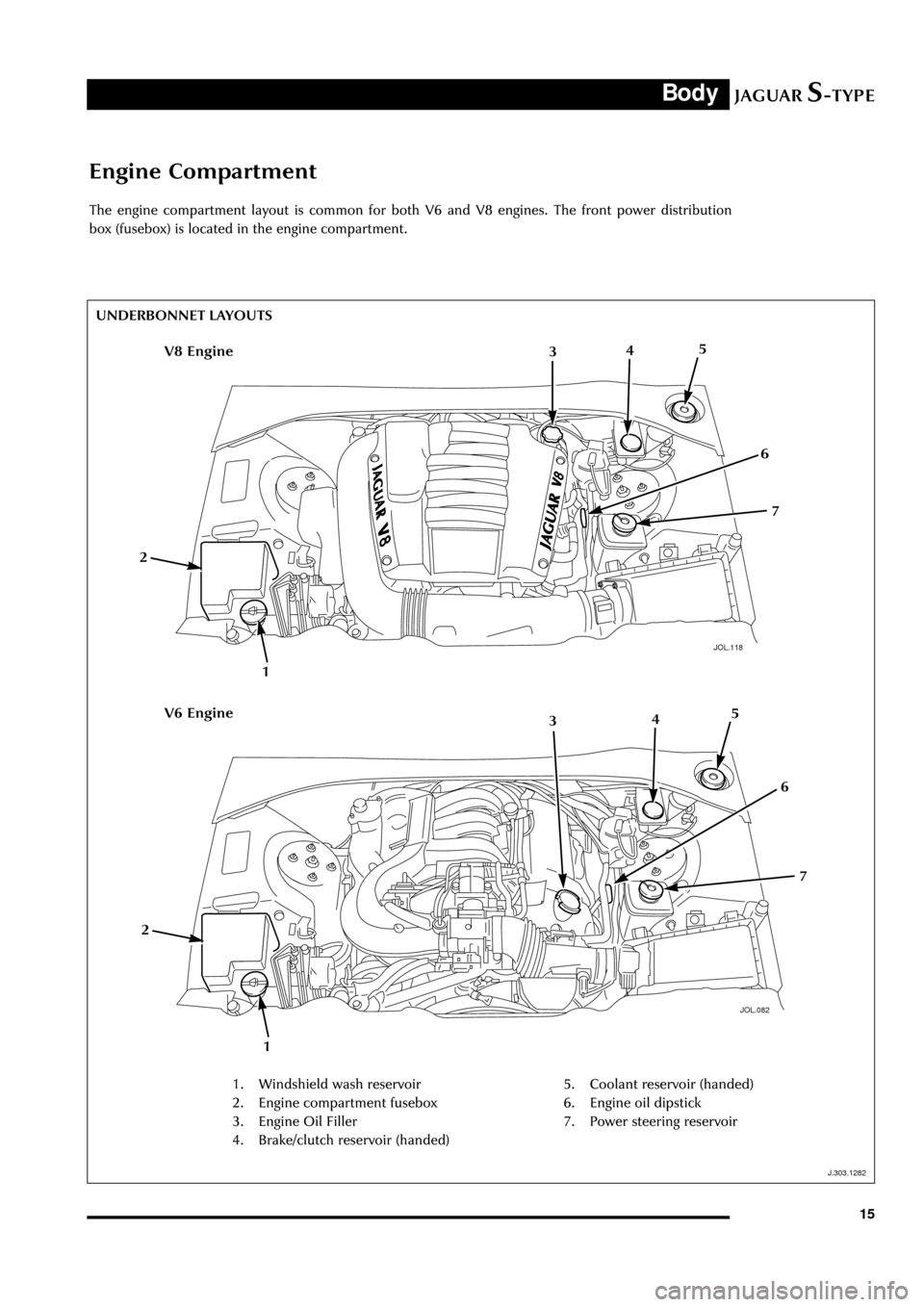
The engine compartment layout is common for both V6 and V8 engines. The front power distribution
box (fusebox) is located in the engine compartment.
JOL.118
UNDERBONNET LAYOUTS
J.303.1282
1
V8 Engine
JOL.082
V6 Engine
1. Windshield wash reservoir
2. Engine compartment fusebox
3. Engine Oil Filler
4. Brake/clutch reservoir (handed)5. Coolant reservoir (handed)
6. Engine oil dipstick
7. Power steering reservoir
543
2
7
6
1
543
2
7
6
Page 38 of 133
JAGUARS-TYPEOccupant Protection
33
Airbags
Driver Airbag
The driver airbag module is fitted in the centre of
the steering wheel and is of conventional design.
A reduced charge propellant (Ôde-poweredÕ) is
used to minimise impact effects where the driver
is seated close to the wheel.
The module is secured by two side screws on the
left and right underside of the steering wheel.
Passenger Airbag
WARNING:
Do not place objects on the passenger airbag
deployment panel. Injury could occur if the
airbag contacts an object during inflation.
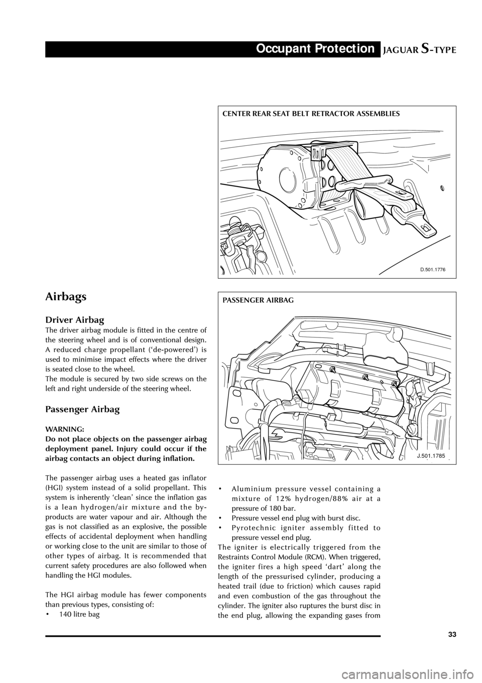
The passenger airbag uses a heated gas inflator
(HGI) system instead of a solid propellant. This
system is inherently ÔcleanÕ since the inflation gas
is a lean hydrogen/air mixture and the by-
products are water vapour and air. Although the
gas is not classified as an explosive, the possible
effects of accidental deployment when handling
or working close to the unit are similar to those of
other types of airbag. It is recommended that
current safety procedures are also followed when
handling the HGI modules.
The HGI airbag module has fewer components
than previous types, consisting of:
¥ 140 litre bag
D.501.1776
CENTER REAR SEAT BELT RETRACTOR ASSEMBLIES
J.501.1785
PASSENGER AIRBAG
¥ Aluminium pressure vessel containing a
mixture of 12% hydrogen/88% air at a
pressure of 180 bar.
¥ Pressure vessel end plug with burst disc.
¥ Pyrotechnic igniter assembly fitted to
pressure vessel end plug.
The igniter is electrically triggered from the
Restraints Control Module (RCM). When triggered,
the igniter fires a high speed ÔdartÕ along the
length of the pressurised cylinder, producing a
heated trail (due to friction) which causes rapid
and even combustion of the gas throughout the
cylinder. The igniter also ruptures the burst disc in
the end plug, allowing the expanding gases from
Page 52 of 133
JAGUARS-TYPEChassis
47
Front Suspension
The independent front wheel suspension is a
double wishbone axle arrangement with
aluminium control arms. The two arms are of
different lengths, which minimises the changes in
track and camber. Inclination of the upper control
arm axis provides anti-dive front suspension
action. There are two front cross members,
known as Number 1 and Number 2.
Number 1, the forward cross member, is a steel
fabrication, non-isolated, which locates the lower
control arm front mounting, the anti-roll bar and
the cooling module.
The rear cross member, Number 2, is an
aluminium casting, non-isolated and it locates the
lower control arm rear mounting, the power
steering rack and the engine hydro-mounts.
WARNING: No attempt must be made to
weld or repair the aluminium cross
member. If it is damaged, a new one must
be installed.
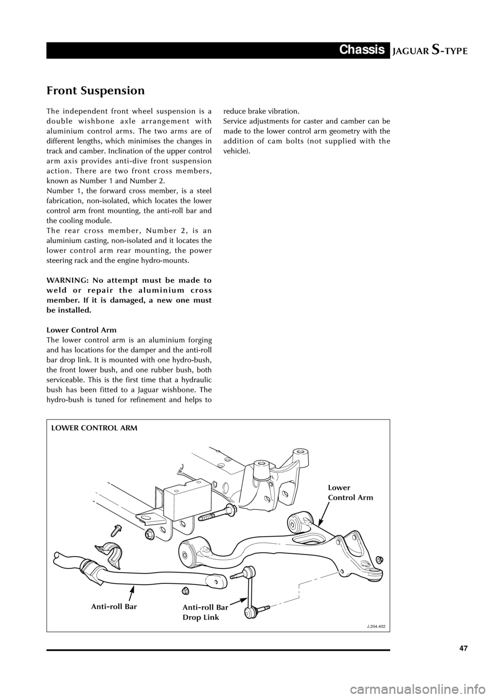
Lower Control Arm
The lower control arm is an aluminium forging
and has locations for the damper and the anti-roll
bar drop link. It is mounted with one hydro-bush,
the front lower bush, and one rubber bush, both
serviceable. This is the first time that a hydraulic
bush has been fitted to a Jaguar wishbone. The
hydro-bush is tuned for refinement and helps to
J.204.402
reduce brake vibration.
Service adjustments for caster and camber can be
made to the lower control arm geometry with the
addition of cam bolts (not supplied with the
vehicle).
LOWER CONTROL ARM
J.204.402
Lower
Control Arm
Anti-roll BarAnti-roll Bar
Drop Link
Page 63 of 133

JAGUARS-TYPEChassis
58
Power Assisted Steering
Introduction
The Jaguar S-TYPE has a variable assist rack and
pinion steering gear and variable rack ratio. The
variable steering rack ratio reduces the number of
turns from lock to lock (2.8) to enhance parking
manoeuvrability whilst maintaining the on-centre
steering precision required at high speed. Full
power assistance is provided for parking. Steering
assistance decreases smoothly at a calibrated rate
to raise driver steering efforts as vehicle speed
increases.
Servicing
There are no carry over parts from XK or XJ Series
vehicles.
The rack is mounted to the rear of cross member
Number 2. The PAS pump is belt driven. A PAS
cooler matrix is located within the radiator
package.
Low PAS pump speeds problems are prevented by
increasing engine speed. A power steering
pressure (PSP) switch senses the demand on the
pump at low engine speeds and increases the
speed to a pre-set minimum.
Hose connections to the pump and the steering
gear are quickfit connectors. The quick connect
tube must be pushed into the existing tube nut
port, along the centreline. The assembly is
complete when the tube end bottoms out in the
port with an audible click/snap. Correct assembly
should be verified by pulling the quickfit tube end.
Servicing of the PAS line involves removal of the
quickfit nut. Replacement PAS lines are supplied
complete with quickfit nut and sealing washer. If
the joint is disturbed it is compulsory to replace
the PTFE sealing ring otherwise leaks are
inevitable. Replacement sealing washers may be
installed with the use of Service tool
D90P-3517-A.
Care must be taken when removing the quickfit
nut from the V6 engine pump as the pulley is
PHENOLIC and is susceptible to damage. The V8
pump installation provides a short jumper tube
from the pump to improve accessibility to the
high-pressure hose connection. The PAS pulley
D.211.247
PA S R AC K
D.211.258
POWER STEERING PRESSURE SWITCH
Page 65 of 133
JAGUARS-TYPEChassis
60
D.211.255
ELECTRICALLY ADJUSTABLE STEERING COLUMN
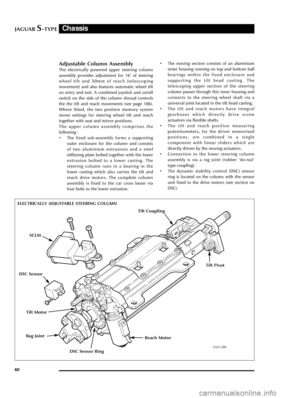
Adjustable Column Assembly
The electrically powered upper steering column
assembly provides adjustment for 16û of steering
wheel tilt and 50mm of reach (telescoping
movement) and also features automatic wheel tilt
on entry and exit. A combined joystick and on/off
switch on the side of the column shroud controls
the the tilt and reach movements (see page 106).
Where fitted, the two position memory system
stores settings for steering wheel tilt and reach
together with seat and mirror positions.
The upper column assembly comprises the
following :
¥ The fixed sub-assembly forms a supporting
outer enclosure for the column and consists
of two aluminium extrusions and a steel
stiffening plate bolted together with the lower
extrusion bolted to a lower casting. The
steering column runs in a bearing in the
lower casting which also carries the tilt and
reach drive motors. The complete column
assembly is fixed to the car cross beam via
four bolts to the lower extrusion.¥ The moving section consists of an aluminium
inner housing running on top and bottom ball
bearings within the fixed enclosure and
supporting the tilt head casting. The
telescoping upper section of the steering
column passes through this inner housing and
connects to the steering wheel shaft via a
universal joint located in the tilt head casting.
¥ The tilt and reach motors have integral
gearboxes which directly drive screw
actuators via flexible shafts.
¥ The tilt and reach position measuring
potentiometers, for the driver memorised
positions, are combined in a single
component with linear sliders which are
directly driven by the moving actuators.
¥ Connection to the lower steering column
assembly is via a rag joint (rubber Ôdo-nutÕ
type coupling).
¥ The dynamic stability control (DSC) sensor
ring is located on the column with the sensor
unit fixed to the drive motors (see section on
DSC).
Tilt Motor
Reach MotorRag Joint
SCLM
DSC Sensor Ring
DSC Sensor
Tilt Coupling
Tilt Pivot
Page 67 of 133
JAGUARS-TYPEChassis
62
J.211.257
STEERING COLUMN LOCK MODULE
Steering Column Lock (where fitted)
Lock Operation
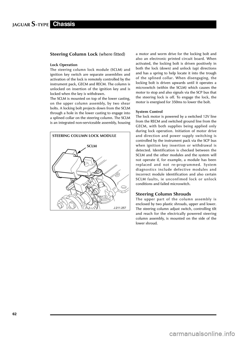
The steering column lock module (SCLM) and
ignition key switch are separate assemblies and
activation of the lock is remotely controlled by the
instrument pack, GECM and RECM. The column is
unlocked on insertion of the ignition key and is
locked when the key is withdrawn.
The SCLM is mounted on top of the lower casting,
on the upper column assembly, by two shear
bolts. A locking bolt projects down from the SCLM
through a hole in the lower casting to engage into
a splined collar on the steering column. The SCLM
is an integrated non-serviceable assembly, housinga motor and worm drive for the locking bolt and
also an electronic printed circuit board. When
activated, the locking bolt is driven positively in
both the lock (down) and unlock (up) directions
and has a spring to help locate it into the trough
of the splined collar. When disengaging, the
locking bolt is driven upwards until it operates a
microswitch (within the SCLM) which causes the
motor to stop and also signals via the SCP bus that
the steering lock is off. To engage the lock, the
motor is energised for 350ms to lower the bolt.
System Control
The lock motor is powered by a switched 12V line
from the RECM and switched ground line from the
GECM, with both supplies being applied only
during lock operation. Initiation of motor drive
and direction and power supply switching is
controlled by the instrument pack via the SCP bus
when ignition key insertion or withdrawal is
detected. Identification is checked between the
SCLM and the other modules and the system will
not operate if, for example, a module has been
replaced and not re-programmed. System
diagnostics include defective modules and
incorrect module identification and also certain
SCLM faults, ie unconfimed lock or unlock
conditions and failed microswitch.
Steering Column Shrouds
The upper part of the column assembly is
enclosed by two plastic shrouds, upper and lower.
The steering column adjust switch, controlling tilt
and reach for the electrically powered steering
column assembly, is mounted on the side of the
lower shroud.
SCLM