303 JAGUAR X308 1998 2.G Workshop Manual
[x] Cancel search | Manufacturer: JAGUAR, Model Year: 1998, Model line: X308, Model: JAGUAR X308 1998 2.GPages: 2490, PDF Size: 69.81 MB
Page 703 of 2490

1.
Fit the camshaft to position in the cylinder head, with
the timing flats uppermost.
2. Fit the camshaft caps to their respective locations (0 to 4 from the front) and in the correct orientation
(arrow to front of engine).
3. Fit and tighten the cap securing bolts. Tighten evenly,
in stages, to 9 - 11 Nm.
3. Fit the camshaft locking tool 303 - 530 (fitted for following
operation) align the camshaft as necessary.
4. Refit the VVT Unit to the A-Bank. Refer to Operation 12.65.70.
This also includes the VVT Bu sh Carrier Assembly, Primary
Chain and Tensioner.
5. With the camshaft (303 - 530) and crankshaft (303 - 531)
setting tools removed, after the previous operation, adjust the
valve clearances on the inlet camshaft. refer to Operation
12.29.48.
6. Refit the Timing Cover. Re fer to Operation 12.65.01.
7. Move the engine compartment co ver from the service position
and connect the gas struts.
8. Remove the paint protection sheets and close the cover.
9. Connect the battery and fit the battery cover.
пЃ¬Re
fer to the Battery Reconnection Procedure 86.15.15.
Page 704 of 2490

Engine - Intake Manifol
d
In-v
ehic
le Repair
Remov
a
l
W
A
RNING: BEFORE PROCEEDING, IT IS ESSENTIAL THAT
THE WARNINGS GIVEN IN SECTION 100-00 (UNDER THE
HEADING 'SAFETY PRECAUTIONS') ARE READ AND UNDERSTOOD.
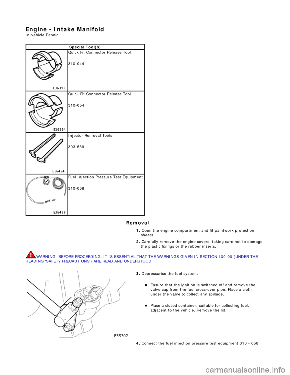
S p
ecial Tool(s)
Qu
ic
k Fit Connector Release Tool
310-044
Qu ic
k Fit Connector Release Tool
310-054
Inject or Remov
al Tools
303-539
F u
el Injection Pressu
re Test Equipment
310-058
1. Open the engine compartment and fit paintwork protection
sheets.
2. Carefully remove the en gine covers, taking care not to damage
the plastic fixings or the rubber inserts.
3. Depress
urise the fuel system.
пЃ¬E
n
sure that the ignition is
switched off and remove the
valve cap from the fuel cross-over pipe. Place a cloth
under the valve to collect any spillage.
пЃ¬Pla c
e a closed container, su
itable for collecting fuel,
adjacent to the vehicle. Remove the lid.
4. Connect the fuel injection pres sure test equipment 310 - 058
Page 710 of 2490

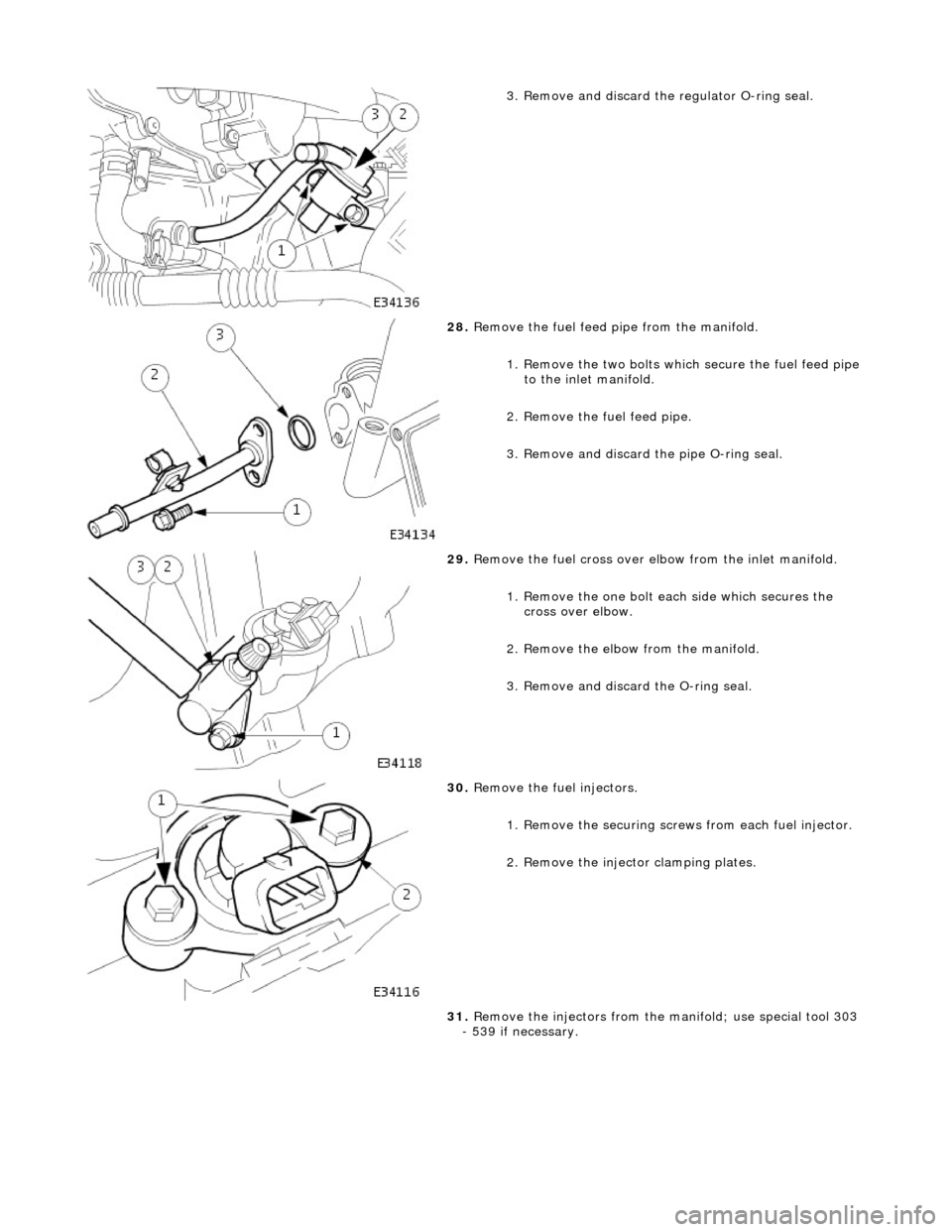
3. Remove and discard the regulator O-ring seal.
28. Remove the fuel feed pipe from the manifold.
1. Remove the two bolts which secure the fuel feed pipe
to the inlet manifold.
2. Remove the fuel feed pipe.
3. Remove and discard the pipe O-ring seal.
29. Remove the fuel cross over elbow from the inlet manifold.
1. Remove the one bolt each side which secures the cross over elbow.
2. Remove the elbow from the manifold.
3. Remove and discard the O-ring seal.
30. Remove the fuel injectors.
1. Remove the securing scre ws from each fuel injector.
2. Remove the inject or clamping plates.
31. Remove the injectors from the ma nifold; use special tool 303
- 539 if necessary.
Page 716 of 2490

пЃ¬Tighten the locknut without altering the setting or
introducing twist into the cable outer
пЃ¬Check the kickdown setting using the PDU. For scan tool
procedure, refer to 303-14 , Throttle cable, Renew
21. Reconnect the multi-plugs to the throttle body.
1. Connect the throttle body motor multi-plug.
2. Connect the two potentiometer multi-plugs, one each side of the throttle.
3. Connect the vacuum pipe elbow to the throttle
actuator.
22. Fit the intake tube / air flow meter / air cleaner cover
assembly.
1. Fit a new rubber seal; air in take tube to throttle body.
2. Fit the intake tube / air flow meter / air cleaner cover
assembly.
23. Reconnect the air cleaner cover.
1. Fit the five clips which secure the air cleaner cover.
24. Connect the intake tube to the throttle body.
1. Connect the intake tube to the throttle body.
2. Fit the two bolts which secure the intake tube to the throttle body.
Page 726 of 2490

11. Reconnect the multi-plug, located on the bracket under the
left side of th e throttle body.
12. Connect the coolant hoses to the throttle body.
пЃ¬Remove the blanking plugs from the hoses.
пЃ¬Connect the coolant feed hose and secure with the clip.
пЃ¬Connect the coolant return hose and secure with the clip.
13. CAUTION: Under no circumstances may the quadrant be held clear of the throttle stop by cable tension
Refit the throttle cable and ensure that there is neither tension
nor slack in the cable
пЃ¬Tighten the locknut without altering the setting or
introducing twist into the cable outer
пЃ¬Check the kickdown setting us ing the PDU. For scan tool
procedure, refer to 303-14 , Throttle cable, Renew
14. Reconnect the multi-plugs to the throttle body.
1. Connect the throttle body motor multi-plug.
2. Connect the two potentiometer multi-plugs, one each side of the throttle.
Page 759 of 2490

Engine - Primary Timing Chain LH4.0L NA V8 - AJ27
In-vehicle Repair
Removal
Special Tool(s)
Camshaft setting
303 - 530
Timing chain tensioning
303 - 532
Wedges, primary chain
303 - 533
Crankshaft setting
303 - 531
1. Open the engine compartment and fit paintwork protection
sheets.
2. Set the engine compartment cover to the service access
position.
3. Disconnect the batt ery ground cable.
пЃ¬Remove the battery cover.
4. Remove the Timing Co ver. Refer to Operation 12.65.01 in this
Section.
5. Remove the VVT bush carrier from the A-Bank.
1. Remove the three bolts which secure the carrier to the cylinder block.
Page 761 of 2490

2. Remove the access grommet (for torque converter bolts) from the housing.
11. Fit the damper securing bolt (old one) to the crankshaft,
hand-tight only.
12. Rotate the crankshaft until the triangular arrow indent on
the drive plate is visible thro ugh the access hole; confirm
that the timing flat on ea ch camshaft is uppermost.
13. Fit the crankshaft setting peg 303 - 531 to the crankshaft
position sensor location.
1. Fit the crankshaft setting peg 303 - 531.
1. Position the crankshaft so that the setting peg engages fully into the timing slot.
2. Fit and tighten the bolt to secure the setting peg.
14. Remove the damper securing bolt from the crankshaft.
15. Lower the vehicle on the ramp.
16. Fit the camshaft locking tool 303 - 530 to the A-Bank
camshafts, aligning the shafts slightly as necessary.
17. Loosen the bolt which secures the sprocket to the camshaft.
Page 763 of 2490

22. Remove the chain from the VVT unit and from the crankshaft
pulley.
23. Remove the camshaft locking tool 303 - 530 and transfer it to the B-Bank camshafts, aligning the shafts slightly as necessary.
24. Loosen the bolt which secures the sprocket to the camshaft.
25. Loosen the bolt which secures the VVT unit to the camshaft.
26. Remove the primary ch ain tensioner bolts.
Page 764 of 2490

Installation
27. Remove the tensioner assembly.
1. Remove the tensioner.
2. Remove the tensioner back-plate.
28. Remove the chain tensioner blade.
1. Remove the pivot bolt which secures the tensioner blade.
2. Remove the tensioner blade.
29. Reposition the VVT unit and exhaust camshaft sprocket
forward along the camshaft bosses and remove the chain from
the VVT unit and from th e crankshaft sprocket.
30. Note the orientation of the spro ckets relative to each other
(half a tooth out of line).
31. Clean and inspect all relevant components.
1. Fit the chain tensioning tool 303 - 532 to the exhaust camshaft
Page 765 of 2490

sprocket, B-Bank.
пЃ¬Reposition the sprocket (and the VVT unit) for the most
advantageous position for use of the tool.
пЃ¬Remove the tool.
2. Refit the primary timing chain, B-Bank.
1. Fit the primary chain over the crankshaft sprocket and the VVT unit sprocket. There must be no slack on
the drive side of the primary chain and the VVT unit
must not be rotate d on the camshaft.
пЃ¬Slide the VVT and exhaust sprocket fully rearwards onto
the respective camshafts.
3. Fit the primary chain tensioner blade.
1. Position the tensioner blade to the cylinder block.
2. Fit the retaining / pivot bolt and tighten it to 12 - 16 Nm.
4. Refit the primary chain tensione r assembly. Refer to Operation
12.65.55 in this Section.
пЃ¬Use a wedge 303 - 533 (or two if required) between the
primary chain tensioner and te nsioner blade, to take up
the slack in the chain.
5. Tighten the exhaust camshaft sprocket securing bolt.
1. Fit the chain tensioner tool 303 - 532 to the sprocket holes.
1. Apply force to the tool in an anti-clockwise direction
to tension the chain on its drive side.
2. Whilst applying the opposing force to the sprocket