buttons JAGUAR X308 1998 2.G Workshop Manual
[x] Cancel search | Manufacturer: JAGUAR, Model Year: 1998, Model line: X308, Model: JAGUAR X308 1998 2.GPages: 2490, PDF Size: 69.81 MB
Page 1744 of 2490
Speed Control - Speed
Control
D
iagn
osis and Testing
Pri
n
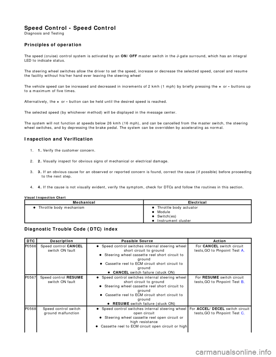
ciples of operation
The s
p
eed (cruise) control sy
stem is activated by an ON/OFF master switch in the J-gate surround, which has an integral
LED to indicate status.
The steering wheel switches allow the driver to set the speed, increase or decrease the selected speed, cancel and resume
the facility without his/her hand ever leaving the steering wheel
The vehicle speed can be increased an d decreased in increments of 2 kmh (1 mph) by briefly pressing the + or - buttons up
to a maximum of five times.
Alternatively, the + or - button can be held until th e desired speed is reached.
The selected speed (by whichever method) w ill be displayed in the message center.
The system will not function at speeds below 26 kmh (16 mph), and can be cancelled from the master switch, the steering
wheel switches, and by depressing th e brake pedal. The system can be overridden by accelerating as normal.
In
spection and Verification
1.
1. Veri fy the customer concern.
2. 2. Vis
ually inspect for obvious signs of mechanical or electrical damage.
3. 3. If an obvious cause for an observed or reported concern is found, correct the cause (if possible) before proceeding
to the next step.
4. 4. If the cause is not visually evident, verify the symptom, check for DTCs and follow the routines in this section.
Vi
sual Inspection Chart
Diagnostic Trouble Code (D
TC) index
MechanicalElectrical
Throttle body mechan
ism
Throttle body actuator
Module Switch(es) Instrument cluster
DTC
De
scr
iption
Possib
l
e Source
Acti
o
n
P0566Speed
c
ontrol
CANCEL
switch ON fault
Speed
control switches internal steering wheel
short circuit to ground
St
eering wheel cassette reel short circuit to
ground
Cassette reel to ECM circ
uit short circuit to
ground
CANCEL
switch failure (stuck ON)
Fo
r
CANCEL switch circuit
tests,GO to Pinpoint Test A.
P0567Speed c
ontrol
RESUME
switch ON fault
Speed
control switches internal steering wheel
short circuit to ground
St
eering wheel cassette reel short circuit to
ground
Cassette reel to ECM circ
uit short circuit to
ground
RESUME swit
ch failure (stuck ON)
For
RESUME switch circuit
tests,GO to Pinpoint Test B.
P0568Spee
d control switch
ground malfunction
Speed
control switches internal steering wheel
open circuit
St
eering wheel cassette reel open circuit or
high resistance
Cassette reel to ECM ci
rcuit open circuit or high
For
ACCEL/DECEL switch circuit
tests,GO to Pinpoint Test C.
Page 1822 of 2490
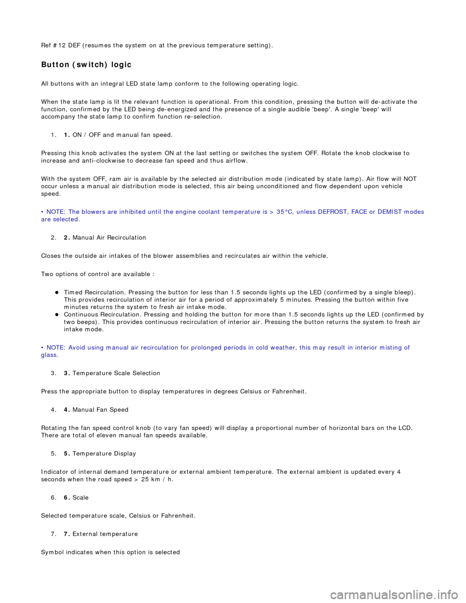
Ref #12 DEF (resumes the system on at the previous temperature setting).
Button (switch) logic
All buttons with an integral LED state lamp conform to the following operating logic.
When the state lamp is lit the relevant func tion is operational. From this condition, pressing the button will de-activate the
function, confirmed by the LED being de-energized and the pres ence of a single audible 'beep'. A single 'beep' will
accompany the state lamp to confirm function re-selection.
1. 1. ON / OFF and manual fan speed.
Pressing this knob activates the system ON at the last settin g or switches the system OFF. Rotate the knob clockwise to
increase and anti-clockwise to decrease fan speed and thus airflow.
With the system OFF, ram air is available by the selected air di stribution mode (indicated by state lamp). Air flow will NOT
occur unless a manual air distribution mo de is selected, this air being unconditioned and flow dependent upon vehicle
speed.
• NOTE: The blowers are inhibited until the engine coolant te mperature is > 35°C, unless DEFROST, FACE or DEMIST modes
are selected.
2. 2. Manual Air Recirculation
Closes the outside air intakes of the blower asse mblies and recirculates air within the vehicle.
Two options of control are available :
Timed Recirculation. Pressing the button for less than 1.5 seconds lights up the LED (confirmed by a single bleep).
This provides recirculation of interior air for a period of approximately 5 minutes. Pressing the button within five
minutes returns the system to fresh air intake mode.
Continuous Recirculation. Pressing and holding the button for more than 1.5 seconds lights up the LED (confirmed by two beeps). This provides continuous reci rculation of interior air. Pressing the button returns the system to fresh air
intake mode.
• NOTE: Avoid using manual air recirculatio n for prolonged periods in cold weather, this may result in interior misting of
glass.
3. 3. Temperature Scale Selection
Press the appropriate button to display temperatures in degrees Celsius or Fahrenheit.
4. 4. Manual Fan Speed
Rotating the fan speed control knob (to vary fan speed) will di splay a proportional number of horizontal bars on the LCD.
There are total of eleven manual fan speeds available.
5. 5. Temperature Display
Indicator of internal demand temperatur e or external ambient temperature. The external ambient is updated every 4
seconds when the road speed > 25 km / h.
6. 6. Scale
Selected temperature scale, Celsius or Fahrenheit.
7. 7. External temperature
Symbol indicates when this option is selected
Page 1823 of 2490
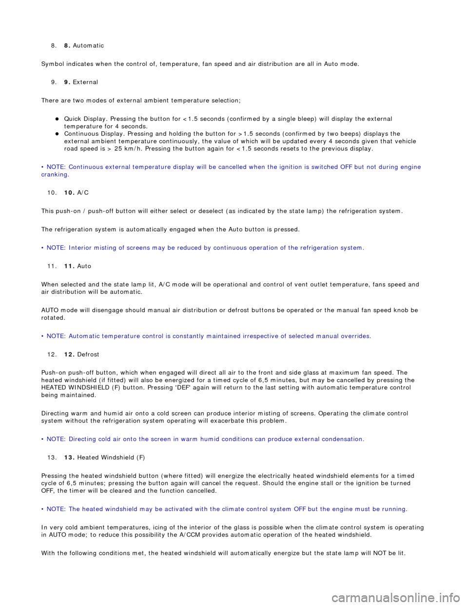
8.8. Automatic
Symbol indicates when the control of , temperature, fan speed and air distribution are all in Auto mode.
9. 9. External
There are two modes of external ambient temperature selection;
Quick Display. Pressing the button for <1.5 seconds (con firmed by a single bleep) will display the external
temperature for 4 seconds.
Continuous Display. Pressing and holding the button fo r >1.5 seconds (confirmed by two beeps) displays the
external ambient temperature continuously, the value of which will be updated every 4 seconds given that vehicle
road speed is > 25 km/h. Pressing the button again fo r <1.5 seconds resets to the previous display.
• NOTE: Continuous external temperature display will be cancel led when the ignition is switched OFF but not during engine
cranking.
10. 10. A/C
This push-on / push-off button will either select or deselect (as indicated by the state lamp) the refrigeration system.
The refrigeration system is automatically engaged when the Auto button is pressed.
• NOTE: Interior misting of screens may be reduced by continuous operation of th e refrigeration system.
11. 11. Auto
When selected and the state lamp lit, A/C mode will be operat ional and control of vent outlet temperature, fans speed and
air distribution will be automatic.
AUTO mode will disengage should manual air distribution or defrost buttons be operated or the manual fan speed knob be
rotated.
• NOTE: Automatic temperature control is constantly main tained irrespective of selected manual overrides.
12. 12. Defrost
Push-on push-off button, which when engaged will direct all air to the front and side glass at maximum fan speed. The
heated windshield (if fitted) will also be energized for a timed cycle of 6,5 minute s, but may be cancelled by pressing the
HEATED WINDSHIELD (F) button. Pressing 'DEF' again will retu rn to the last setting with automatic temperature control
being maintained.
Directing warm and humid air onto a cold screen can produce interior misting of screens. Operating the climate control
system without the refrigerati on system operating will exacerbate this problem.
• NOTE: Directing cold air onto the screen in warm humid conditions can produce external condensation.
13. 13. Heated Windshield (F)
Pressing the heated windshield button (whe re fitted) will energize the electrically heated windshield elements for a timed
cycle of 6,5 minutes; pressing the button again will cancel the request. Should the engine stall or the ignition be turned
OFF, the timer will be cleare d and the function cancelled.
• NOTE: The heated windshield may be activated with the cl imate control system OFF but the engine must be running.
In very cold ambient temperatures, icing of the interior of the glass is possible when the climate control system is operating
in AUTO mode; to reduce this poss ibility the A/CCM provides automatic operation of the heated windshield.
With the following conditions met, the heated windshield will automatically energize but the state lamp will NOT be lit.
Page 1836 of 2490
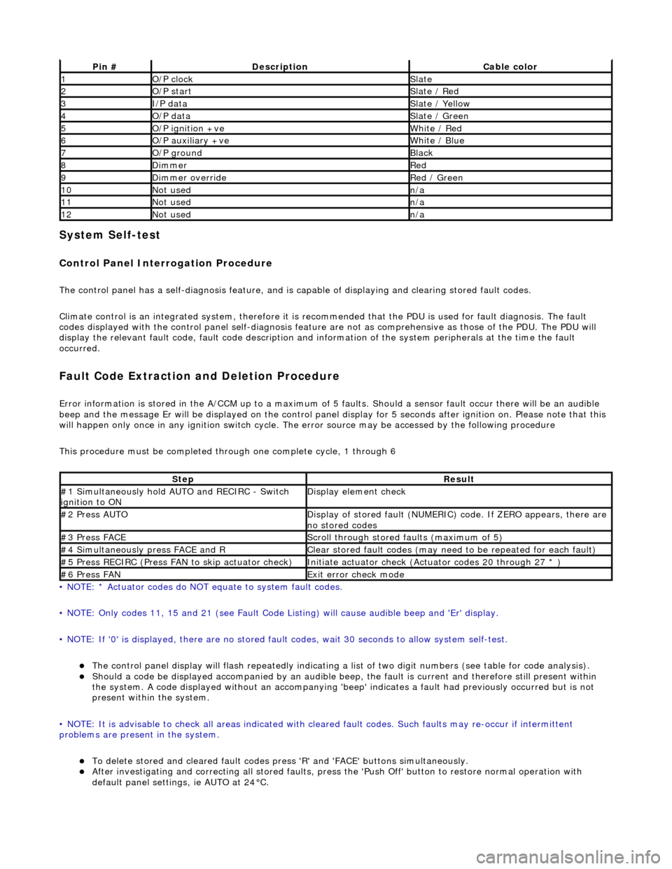
System Self-test
Control Panel Interrogation Procedure
The control panel has a self-diagnosis feature, and is capable of displaying and clearing stored fault codes.
Climate control is an integrated system, therefore it is recommended that the PDU is used for fault diagnosis. The fault
codes displayed with the control panel self -diagnosis feature are not as comprehensive as those of the PDU. The PDU will
display the relevant fault code, fault co de description and information of the system peripherals at the time the fault
occurred.
Fault Code Extraction and Deletion Procedure
Error information is stored in the A/CCM up to a maximum of 5 faults. Should a sensor fault occur there will be an audible
beep and the message Er will be displayed on the control panel display for 5 seco nds after ignition on. Please note that this
will happen only once in any ignition switch cycle. The error source may be accessed by the following procedure
This procedure must be completed through one complete cycle, 1 through 6
• NOTE: * Actuator codes do NOT equate to system fault codes.
• NOTE: Only codes 11, 15 and 21 (see Fault Code List ing) will cause audible beep and 'Er' display.
• NOTE: If '0' is displayed, there are no stored faul t codes, wait 30 seconds to allow system self-test.
The control panel display will flash repeatedly indicating a list of two digit numbers (see table for code analysis). Should a code be displayed accompanied by an audible beep, the fault is current and therefore still present within
the system. A code displayed without an accompanying 'bee p' indicates a fault had previously occurred but is not
present within the system.
• NOTE: It is advisable to check all areas indicated with cleared fault codes. Such faults may re-occur if intermittent
problems are present in the system.
To delete stored and cleared fault codes press 'R' and 'FAC E' buttons simultaneously. After investigating and correcting all stored faults, press the 'Push Off' button to restore normal operation with
default panel settings, ie AUTO at 24°C.
Pin #DescriptionCable color
1O/P clockSlate
2O/P startSlate / Red
3I/P dataSlate / Yellow
4O/P dataSlate / Green
5O/P ignition +veWhite / Red
6O/P auxiliary +veWhite / Blue
7O/P groundBlack
8DimmerRed
9Dimmer overrideRed / Green
10Not usedn/a
11Not usedn/a
12Not usedn/a
StepResult
#1 Simultaneously hold AU TO and RECIRC - Switch
ignition to ONDisplay element check
#2 Press AUTODisplay of stored fault (NUMERIC) code. If ZERO appears, there are
no stored codes
#3 Press FACEScroll through stored faults (maximum of 5)
#4 Simultaneously press FACE and RClear stored fault codes (may need to be repeated for each fault)
#5 Press RECIRC (Press FAN to skip actuator check)Initiate actuator check (Actuator codes 20 through 27 * )
#6 Press FANExit error check mode
Page 1838 of 2490
System Self-test
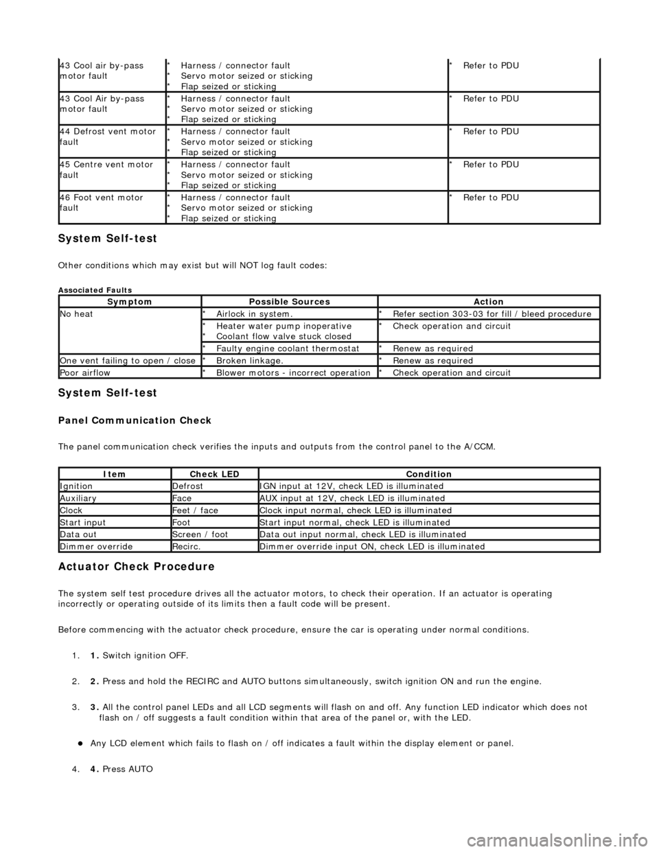
Other conditions which may exist but will NOT log fault codes:
Associated Faults
System Self-test
Panel Communication Check
The panel communication check veri fies the inputs and outputs from the control panel to the A/CCM.
Actuator Check Procedure
The system self test procedure drives all the actuator moto rs, to check their operation. If an actuator is operating
incorrectly or operating outside of its limi ts then a fault code will be present.
Before commencing with the actuator check procedure, ensure the ca r is operating under normal conditions.
1. 1. Switch ignition OFF.
2. 2. Press and hold the RECIRC and AUTO buttons simult aneously, switch ignition ON and run the engine.
3. 3. All the control panel LEDs and all LCD segments will flas h on and off. Any function LED indicator which does not
flash on / off suggests a fault condition within that area of the panel or, with the LED.
Any LCD element which fails to flash on / off indicates a fault within the display element or panel.
4. 4. Press AUTO
43 Cool air by-pass
motor faultHarness / connector fault
Servo motor seized or sticking
Flap seized or sticking
*
*
*Refer to PDU
*
43 Cool Air by-pass
motor faultHarness / connector fault
Servo motor seized or sticking
Flap seized or sticking
*
*
*Refer to PDU
*
44 Defrost vent motor
faultHarness / connector fault
Servo motor seized or sticking
Flap seized or sticking
*
*
*Refer to PDU
*
45 Centre vent motor
faultHarness / connector fault
Servo motor seized or sticking
Flap seized or sticking
*
*
*Refer to PDU
*
46 Foot vent motor
faultHarness / connector fault
Servo motor seized or sticking
Flap seized or sticking
*
*
*Refer to PDU
*
SymptomPossible SourcesAction
No heatAirlock in system.
*Refer section 303-03 for fill / bleed procedure
*
Heater water pump inoperative
Coolant flow valve stuck closed
*
*Check operation and circuit
*
Faulty engine coolant thermostat
*Renew as required
*
One vent failing to open / closeBroken linkage.
*Renew as required
*
Poor airflowBlower motors - incorrect operation
*Check operation and circuit
*
ItemCheck LEDCondition
IgnitionDefrostIGN input at 12V, check LED is illuminated
AuxiliaryFaceAUX input at 12V, check LED is illuminated
ClockFeet / faceClock input normal, check LED is illuminated
Start inputFootStart input normal, check LED is illuminated
Data outScreen / footData out input normal, check LED is illuminated
Dimmer overrideRecirc.Dimmer override input ON, check LED is illuminated