wiring JAGUAR X308 1998 2.G Service Manual
[x] Cancel search | Manufacturer: JAGUAR, Model Year: 1998, Model line: X308, Model: JAGUAR X308 1998 2.GPages: 2490, PDF Size: 69.81 MB
Page 1216 of 2490
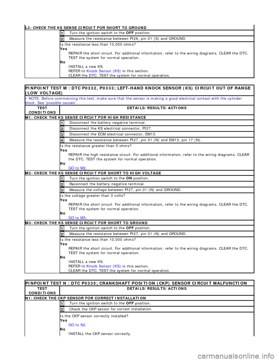
L3
: CHECK THE KS SENSE CIRCUIT FOR SHORT TO GROUND
Turn the ignition swi
t
ch to the OFF
position.
1
Me
asure the resistance between PI26, pin 01 (S) and GROUND.
2
Is
t
he resistance less than 10,000 ohms?
Yes REPAIR the short circuit. For addi tional information, refer to the wiring diagrams. CLEAR the DTC.
TEST the system for normal operation.
No INSTALL a new KS.
REFER to Knock Sensor (KS)
in this
section.
CLEAR the DTC. TEST the system for normal operation.
P INPOINT TES
T M : DTC P0332, P0333; LEFT-H
AND KNOCK SENSOR (KS) CIRCUIT OUT OF RANGE
(LOW VOLTAGE)
•
NOTE: Before commencing this
test, make sure that the sensor is making a good electrical contact with the cylinder
block. See 'possible causes'.
TE S
T
CONDITIONS
D E
TAILS/RESULTS/ACTIONS
M1: CHECK THE KS SEN
S
E CI
RCUIT FOR HIGH RESISTANCE
Di
sc
onnect the battery negative terminal.
1
Di
sc
onnect the KS electrical connector, PI27.
2
D
i
sconnect the ECM electrical connector, EM13.
3
M
e
asure the resistance between PI27, pin 01 (N) and EM13, pin 17 (N).
4
Is th
e res
istance greater than 5 ohms?
Yes REPAIR the high resistance circui t. For additional information, refer to the wiring diagrams. CLEAR
the DTC. TEST the system for normal operation.
No GO to M2
.
M2: CHECK TH
E KS SENSE CIRCUIT FOR SHORT TO HIGH VOLTAGE
Turn the ignition swi
t
ch to the ON
position.
1
Re
connect the battery negative terminal.
2
Meas
ure t
he voltage between PI27, pin 01 (N) and GROUND.
3
Is th
e volt
age greater than 3 volts?
Yes REPAIR the short circuit. For addi tional information, refer to the wiring diagrams. CLEAR the DTC.
TEST the system for normal operation.
No GO to M3
.
M3: CHECK TH
E KS SENSE CIRCUIT FOR SHORT TO GROUND
Turn the ignition swi
t
ch to the OFF
position.
1
Measure t
he resistance between PI27, pin 01 (N) and GROUND.
2
Is
t
he resistance less than 10,000 ohms?
Yes REPAIR the short circuit. For addi tional information, refer to the wiring diagrams. CLEAR the DTC.
TEST the system for normal operation.
No INSTALL a new KS.
REFER to Knock Sensor (KS)
in this
section.
CLEAR the DTC. TEST the system for normal operation.
PINPOINT TEST N : DTC P0335;
CRANKSHAFT POSITION (CKP) SENSOR CIRCUIT MALFUNCTION
TE
S
T
CONDITIONS
D E
TAILS/RESULTS/ACTIONS
N
1: CH
ECK THE CKP SENSOR FOR CORRECT INSTALLATION
Turn the ignition swi
t
ch to the OFF
position.
1
Check the CKP sen
sor fo
r correct installation.
2
Is the CK
P sensor correctly installed?
Yes GO to N2
.
No
INST
ALL the CKP sensor correctly.
Page 1217 of 2490
REF
ER to
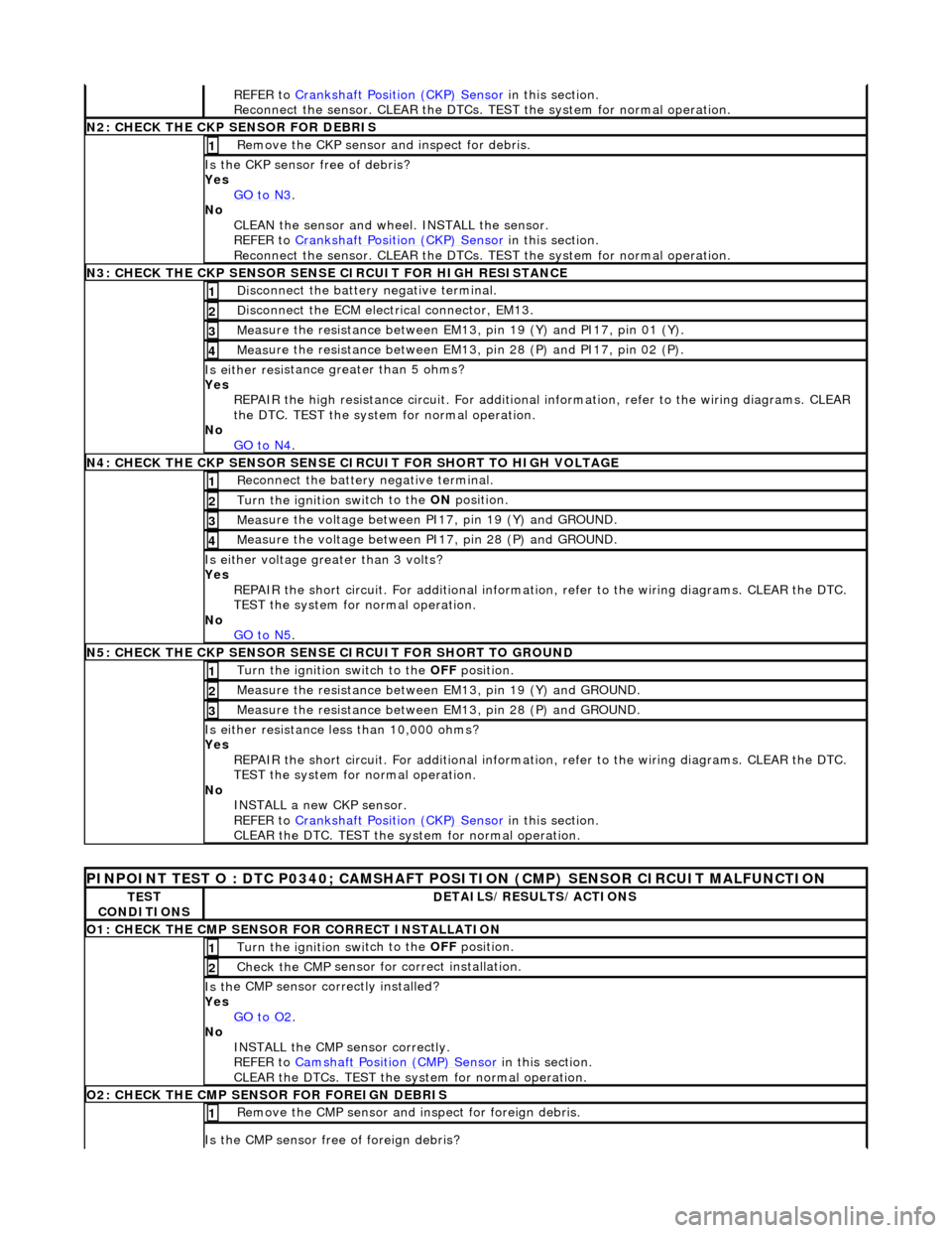
Crankshaft Position (CKP) Sensor
in this section.
Reconnect the sensor. CLEAR the DTCs. TE ST the system for normal operation.
N
2: CHECK THE CKP SENSOR FOR DEBRIS
Re
move the CKP sensor
and inspect for debris.
1
Is the CKP sensor free of
debris?
Yes GO to N3
.
No
CLEAN the sensor and whee l. INSTALL the sensor.
REFER to Crankshaft Position (CKP) Sensor
in this section.
Reconnect the sensor. CLEAR the DTCs. TE ST the system for normal operation.
N
3: CHECK THE CKP SENSOR SENSE CIRCUIT FOR HIGH RESISTANCE
Di
sconnect the battery negative terminal.
1
D
isconnect the ECM electrical connector, EM13.
2
Me
asure the resistance between EM13, pin 19 (Y) and PI17, pin 01 (Y).
3
Meas
ure the resistance between EM13, pin 28 (P) and PI17, pin 02 (P).
4
Is either resi
stance
greater than 5 ohms?
Yes REPAIR the high resistance circui t. For additional information, refer to the wiring diagrams. CLEAR
the DTC. TEST the system for normal operation.
No GO to N4
.
N
4: CHECK THE CKP SENSOR SENSE CI
RCUIT FOR SHORT TO HIGH VOLTAGE
R
econnect the battery negative terminal.
1
Turn the ignition swi
tch to the ON
position.
2
Meas
ure the voltage between PI17, pin 19 (Y) and GROUND.
3
M
easure the voltage between PI17, pin 28 (P) and GROUND.
4
Is ei
ther voltage greater than 3 volts?
Yes REPAIR the short circuit. For addi tional information, refer to the wiring diagrams. CLEAR the DTC.
TEST the system for normal operation.
No GO to N5
.
N
5: CHECK THE CKP SENSOR SENSE CIRCUIT FOR SHORT TO GROUND
Turn the ignition swi
tch to the OFF
position.
1
Meas
ure the resistance between EM13, pin 19 (Y) and GROUND.
2
Meas
ure the resistance between EM13, pin 28 (P) and GROUND.
3
Is either resi
stance
less than 10,000 ohms?
Yes REPAIR the short circuit. For addi tional information, refer to the wiring diagrams. CLEAR the DTC.
TEST the system for normal operation.
No INSTALL a new CKP sensor.
REFER to Crankshaft Position (CKP) Sensor
in this section.
CLEAR the DTC. TEST the system for normal operation.
P
INPOINT TEST O : DTC P0340;
CAMSHAFT POSITION (CMP) SENSOR CIRCUIT MALFUNCTION
TE
ST
CONDITIONS
D
ETAILS/RESULTS/ACTIONS
O1: CHECK THE CM
P SENSOR FOR CORRECT INSTALLATION
Turn the ignition swi
tch to the OFF
position.
1
Check the CMP
sensor fo
r correct installation.
2
Is th
e CMP sensor correctly installed?
Yes GO to O2
.
No
INSTALL the CMP sensor correctly.
REFER to Camshaft Position (CMP) Sensor
in this section.
CLEAR the DTCs. TEST the system for normal operation.
O2: CHECK THE CM
P SENSOR FOR FOREIGN DEBRIS
Re
move the CMP sensor and
inspect for foreign debris.
1
Is the CMP sensor free of
foreign debris?
Page 1218 of 2490
Yes
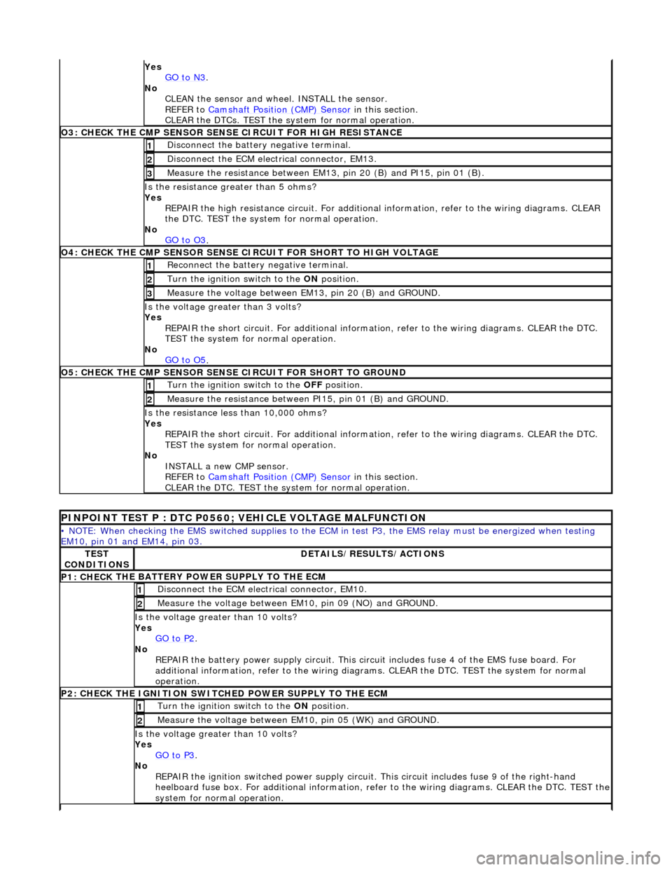
GO to N3.
No
CLEAN th
e sensor and whee
l. INSTALL the sensor.
REFER to Camshaft Position (CMP) Sensor
in this
section.
CLEAR the DTCs. TEST the system for normal operation.
O3: CHECK THE CM P SEN
SOR SENS
E CIRCUIT FOR HIGH RESISTANCE
Disc
onnect the battery negative terminal.
1
D
i
sconnect the ECM electrical connector, EM13.
2
Meas
ure t
he resistance between EM13, pin 20 (B) and PI15, pin 01 (B).
3
Is the res
istance greater than 5 ohms?
Yes REPAIR the high resistance circui t. For additional information, refer to the wiring diagrams. CLEAR
the DTC. TEST the system for normal operation.
No GO to O3
.
O4: CHECK THE CM P SEN
SOR SENSE CI
RCUIT FOR SHORT TO HIGH VOLTAGE
Re
connect the battery negative terminal.
1
Turn the ignition swi
t
ch to the ON
position.
2
Me
asure the voltage between EM13, pin 20 (B) and GROUND.
3
Is th
e volt
age greater than 3 volts?
Yes REPAIR the short circuit. For addi tional information, refer to the wiring diagrams. CLEAR the DTC.
TEST the system for normal operation.
No GO to O5
.
O5: CH ECK THE CM
P SENSOR SENSE CIRCUIT FOR SHORT TO GROUND
Turn the ignition swi
t
ch to the OFF
position.
1
Me
asure the resistance between PI15, pin 01 (B) and GROUND.
2
Is
t
he resistance less than 10,000 ohms?
Yes REPAIR the short circuit. For addi tional information, refer to the wiring diagrams. CLEAR the DTC.
TEST the system for normal operation.
No INSTALL a new CMP sensor.
REFER to Camshaft Position (CMP) Sensor
in this
section.
CLEAR the DTC. TEST the system for normal operation.
P I
NPOINT TEST P : DTC P0560; VEHICLE VOLTAGE MALFUNCTION
•
NOTE
: When checking the EMS switched supplies to the ECM
in test P3, the EMS relay must be energized when testing
EM10, pin 01 and EM14, pin 03.
TE S
T
CONDITIONS
D E
TAILS/RESULTS/ACTIONS
P1: CHECK
THE BATTERY POWER SUPPLY TO THE ECM
D
i
sconnect the ECM electrical connector, EM10.
1
Measure the
voltage between EM 10,
pin 09 (NO) and GROUND.
2
Is the vol
t
age greater than 10 volts?
Yes GO to P2
.
No
REPAIR th
e battery power supply circ
uit. This circuit includes fuse 4 of the EMS fuse board. For
additional information, refer to the wiring diagrams. CLEAR the DT C. TEST the system for normal
operation.
P2: CHECK
THE IGNITION SWITCH
ED POWER SUPPLY TO THE ECM
Turn the ignition swit
ch to the
ON position.
1
Meas
ure t
he voltage between EM10, pin 05 (WK) and GROUND.
2
Is the vol
t
age greater than 10 volts?
Yes GO to P3
.
No
REP
AIR the ignition switched power supply circuit. This circuit includes fuse 9 of the right-hand
heelboard fuse box. For a dditional information, refer to the wiri ng diagrams. CLEAR the DTC. TEST the
system for normal operation.
Page 1219 of 2490
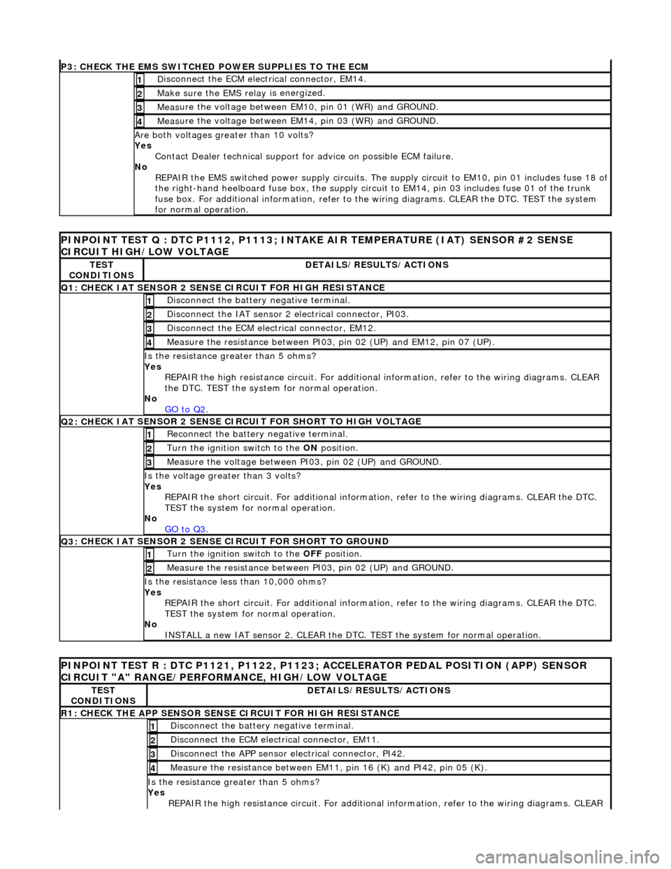
P3: CHECK
THE EMS SWITCHED
POWER SUPPLIES TO THE ECM
D
isconnect the ECM electrical connector, EM14.
1
Make sure the EMS re
lay i
s energized.
2
Meas
ure the voltage between EM10, pin 01 (WR) and GROUND.
3
Meas
ure the voltage between EM14, pin 03 (WR) and GROUND.
4
Are both
voltages greater than 10 volts?
Yes Contact Dealer technical support for advice on possible ECM failure.
No REPAIR the EMS switched power supply circuits. The su pply circuit to EM10, pin 01 includes fuse 18 of
the right-hand heelboard fuse box, the supply circuit to EM14, pin 03 includes fuse 01 of the trunk
fuse box. For additional information, refer to th e wiring diagrams. CLEAR the DTC. TEST the system
for normal operation.
PI
NPOINT TEST Q : DTC P1112, P1113; INTAKE
AIR TEMPERATURE (IAT) SENSOR #2 SENSE
CIRCUIT HIGH/LOW VOLTAGE
TE
ST
CONDITIONS
D
ETAILS/RESULTS/ACTIONS
Q1:
CHECK IAT SENSOR 2 SENSE CIRCUIT FOR HIGH RESISTANCE
Di
sconnect the battery negative terminal.
1
Di
sconnect the IAT sensor 2 electrical connector, PI03.
2
D
isconnect the ECM electrical connector, EM12.
3
Me
asure the resistance between PI03, pin 02 (UP) and EM12, pin 07 (UP).
4
Is th
e resistance greater than 5 ohms?
Yes REPAIR the high resistance circui t. For additional information, refer to the wiring diagrams. CLEAR
the DTC. TEST the system for normal operation.
No GO to Q2
.
Q2: CH
ECK IAT SENSOR 2 SENSE CIRC
UIT FOR SHORT TO HIGH VOLTAGE
R
econnect the battery negative terminal.
1
Turn the ignition swi
tch to the ON
position.
2
Measure the
voltage between PI
03, pin 02 (UP) and GROUND.
3
Is th
e voltage greater than 3 volts?
Yes REPAIR the short circuit. For addi tional information, refer to the wiring diagrams. CLEAR the DTC.
TEST the system for normal operation.
No GO to Q3
.
Q3:
CHECK IAT SENSOR 2 SENSE CIRCUIT FOR SHORT TO GROUND
Turn the ignition swi
tch to the OFF
position.
1
Meas
ure the resistance between PI03, pin 02 (UP) and GROUND.
2
Is
the resistance less than 10,000 ohms?
Yes REPAIR the short circuit. For addi tional information, refer to the wiring diagrams. CLEAR the DTC.
TEST the system for normal operation.
No INSTALL a new IAT sensor 2. CLEAR the DTC. TEST the system for normal operation.
P
INPOINT TEST R : DTC P1121, P1122, P1123;
ACCELERATOR PEDAL POSITION (APP) SENSOR
CIRCUIT "A" RANGE/PERFORMANCE, HIGH/LOW VOLTAGE
TE
ST
CONDITIONS
D
ETAILS/RESULTS/ACTIONS
R1: CHECK THE APP
SENSOR SENSE CIRCUIT FOR HIGH RESISTANCE
Di
sconnect the battery negative terminal.
1
D
isconnect the ECM electrical connector, EM11.
2
Di
sconnect the APP sensor electrical connector, PI42.
3
Meas
ure the resistance between EM11, pin 16 (K) and PI42, pin 05 (K).
4
Is th
e resistance greater than 5 ohms?
Yes REPAIR the high resistance circui t. For additional information, refer to the wiring diagrams. CLEAR
Page 1220 of 2490
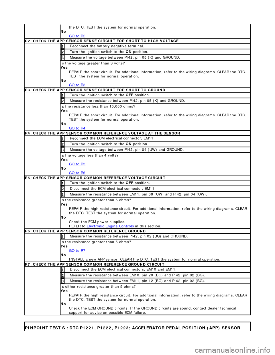
the DT
C. TEST the system for normal operation.
No GO to R2
.
R2: CHECK TH
E APP SENSOR SENSE CIRCUIT FOR SHORT TO HIGH VOLTAGE
R
e
connect the battery negative terminal.
1
Turn the ignition swi
t
ch to the ON
position.
2
Me
asure the voltage between PI42, pin 05 (K) and GROUND.
3
Is th
e volt
age greater than 3 volts?
Yes REPAIR the short circuit. For addi tional information, refer to the wiring diagrams. CLEAR the DTC.
TEST the system for normal operation.
No GO to R3
.
R3: CHECK THE APP SENSOR SENS
E CIRCUIT FOR SHORT TO GROUND
Turn the ignition swi
t
ch to the OFF
position.
1
Me
asure the resistance between PI42, pin 05 (K) and GROUND.
2
Is
t
he resistance less than 10,000 ohms?
Yes REPAIR the short circuit. For addi tional information, refer to the wiring diagrams. CLEAR the DTC.
TEST the system for normal operation.
No GO to R4
.
R4: CHECK THE APP SENSOR COM
MON
REFERENCE VOLTAGE AT THE SENSOR
Reconn
ect the ECM electrical connector, EM11.
1
Turn the ignition swi
t
ch to the ON
position.
2
Measure t
he voltage between PI42, pin 04 (UW) and GROUND.
3
Is th
e volt
age less than 4 volts?
Yes GO to R5
.
No
GO to R6
.
R5: CHECK THE APP SENSOR COM
M
ON REFERENCE VOLTAGE CIRCUIT
Turn the ignition swit
ch to the OFF
position.
1
Di
sconnect the ECM electrical connector, EM11.
2
Measure t
he resistance between EM11,
pin 08 (UW) and PI42, pin 04 (UW).
3
Is the res
istance greater than 5 ohms?
Yes REPAIR the high resistance circui t. For additional information, refer to the wiring diagrams. CLEAR
the DTC. TEST the system for normal operation.
No Check the ECM power supplies.
REFER to Electronic Engine Controls
in this
section.
R6: CHECK THE APP
SENSOR COM
MON REFERENCE GROUND
Meas
ure t
he resistance between PI42, pin 02 (BG) and GROUND.
1
Is th
e res
istance greater than 5 ohms?
Yes GO to R7
.
No
INST
ALL a new APP sensor. CLEAR the DTC.
TEST the system for normal operation.
R7: CHECK THE APP SENSOR COM
MON REFERENCE GROUND CIRCUIT
D
i
sconnect the ECM electrical connectors, EM10 and EM11.
1
Measure t
he resistance between EM10,
pin 20 (BG) and PI42, pin 02 (BG).
2
Measure t
he resistance between EM11,
pin 12 (BG) and PI42, pin 02 (BG).
3
Is either resistance greater
than 5 ohms?
Yes REPAIR the high resistance circui t. For additional information, refer to the wiring diagrams. CLEAR
the DTC. TEST the system for normal operation.
No Check the ECM GROUND circuits. If the GROUND circuits are sound, contact dealer technical
support for advice on possible ECM failure.
PINPO
INT TEST S : DTC P1221, P1222, P1223;
ACCELERATOR PEDAL POSITION (APP) SENSOR
Page 1221 of 2490
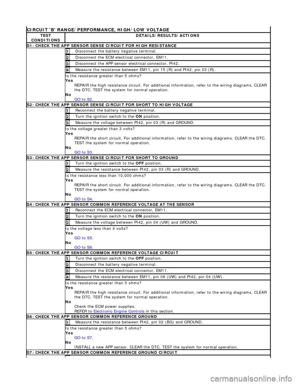
CIRCUI
T 'B' RANGE/PERFORMANCE, HIGH/LOW VOLTAGE
TE
ST
CONDITIONS
D
ETAILS/RESULTS/ACTIONS
S1: CHECK
THE APP SENSOR SENSE CIRCUIT FOR HIGH RESISTANCE
Di
sconnect the battery negative terminal.
1
D
isconnect the ECM electrical connector, EM11.
2
Di
sconnect the APP sensor electrical connector, PI42.
3
Meas
ure the resistance between EM11, pin 15 (R) and PI42, pin 03 (R).
4
Is th
e resistance greater than 5 ohms?
Yes REPAIR the high resistance circui t. For additional information, refer to the wiring diagrams. CLEAR
the DTC. TEST the system for normal operation.
No GO to S2
.
S
2: CHECK THE APP SENSOR SENSE CIRCUIT FOR SHORT TO HIGH VOLTAGE
R
econnect the battery negative terminal.
1
Turn the ignition swi
tch to the ON
position.
2
M
easure the voltage between PI42, pin 03 (R) and GROUND.
3
Is th
e voltage greater than 3 volts?
Yes REPAIR the short circuit. For addi tional information, refer to the wiring diagrams. CLEAR the DTC.
TEST the system for normal operation.
No GO to S3
.
S
3: CHECK THE APP SENSOR SENSE CIRCUIT FOR SHORT TO GROUND
Turn the ignition swi
tch to the OFF
position.
1
Meas
ure the resistance between PI42, pin 03 (R) and GROUND.
2
Is
the resistance less than 10,000 ohms?
Yes REPAIR the short circuit. For addi tional information, refer to the wiring diagrams. CLEAR the DTC.
TEST the system for normal operation.
No GO to S4
.
S4:
CHECK THE APP SENSOR COMMON REFERENCE VOLTAGE AT THE SENSOR
Re
connect the ECM electrical connector, EM11.
1
Turn the ignition swi
tch to the ON
position.
2
Meas
ure the voltage between PI42, pin 04 (UW) and GROUND.
3
Is th
e voltage less than 4 volts?
Yes GO to S5
.
No
GO to S6
.
S5: CHECK
THE APP SENSOR COMM
ON REFERENCE VOLTAGE CIRCUIT
Turn the ignition swi
tch to the OFF
position.
1
Di
sconnect the battery negative terminal.
2
D
isconnect the ECM electrical connector, EM11.
3
Meas
ure the resistance between EM11,
pin 08 (UW) and PI42, pin 04 (UW).
4
Is th
e resistance greater than 5 ohms?
Yes REPAIR the high resistance circui t. For additional information, refer to the wiring diagrams. CLEAR
the DTC. TEST the system for normal operation.
No Check the ECM power supplies.
REFER to Electronic Engine Controls
in this section.
S6: CHECK
THE APP SENSOR COMMON REFERENCE GROUND
Meas
ure the resistance between PI42, pin 02 (BG) and GROUND.
1
Is th
e resistance greater than 5 ohms?
Yes GO to S7
.
No
INSTALL a new APP sensor. CLEAR the DTC. TEST the system for normal operation.
S7: CHECK
THE APP SENSOR COMM
ON REFERENCE GROUND CIRCUIT
Page 1222 of 2490
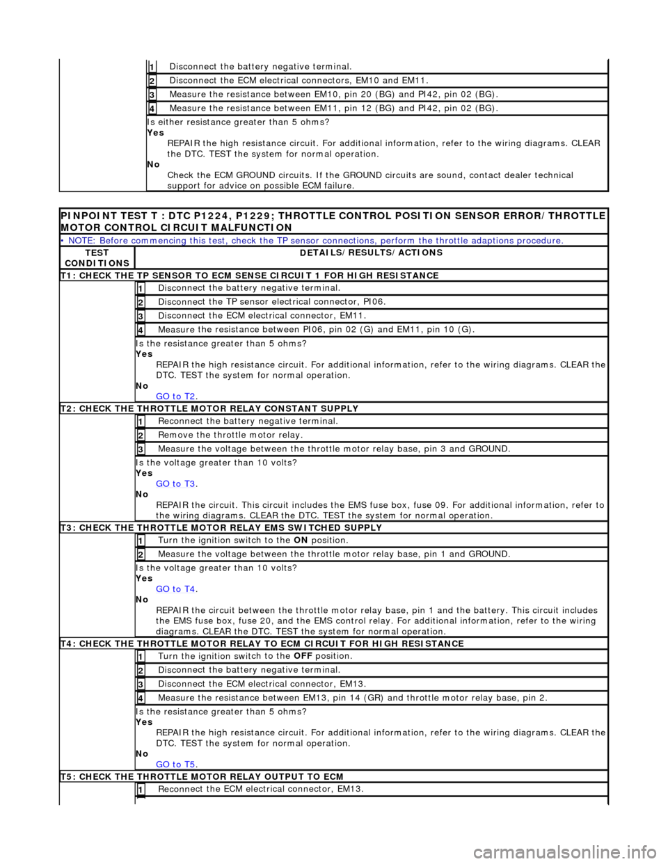
Disc
onnect the battery negative terminal.
1
D
i
sconnect the ECM electrical connectors, EM10 and EM11.
2
Meas
ure t
he resistance between EM10,
pin 20 (BG) and PI42, pin 02 (BG).
3
Measure t
he resistance between EM11,
pin 12 (BG) and PI42, pin 02 (BG).
4
Is either resistance greater
than 5 ohms?
Yes REPAIR the high resistance circui t. For additional information, refer to the wiring diagrams. CLEAR
the DTC. TEST the system for normal operation.
No Check the ECM GROUND circuits. If the GROUND circuits are sound, contact dealer technical
support for advice on possible ECM failure.
PINPOINT TES
T T : DTC P1224, P1229; THROTTLE
CONTROL POSITION SENSOR ERROR/THROTTLE
MOTOR CONTROL CIRCUIT MALFUNCTION
•
NOTE: Before commencing this test, check the TP sensor
connections, perform the throttle adaptions procedure.
TES
T
CONDITIONS
D E
TAILS/RESULTS/ACTIONS
T
1: CH
ECK THE TP SENSOR TO ECM SE
NSE CIRCUIT 1 FOR HIGH RESISTANCE
Disc
onnect the battery negative terminal.
1
Disc
onne
ct the TP sensor electrical connector, PI06.
2
D
i
sconnect the ECM electrical connector, EM11.
3
Me
asure
the resistance between PI06, pin 02 (G) and EM11, pin 10 (G).
4
Is th
e res
istance greater than 5 ohms?
Yes REPAIR the high resistance circuit. For additional information, refer to the wiring diagrams. CLEAR the
DTC. TEST the system for normal operation.
No GO to T2
.
T2
: CHECK THE THROTTLE MOTOR RELAY CONSTANT SUPPLY
R
e
connect the battery negative terminal.
1
R
e
move the thrott
le motor relay.
2
Measure t
he voltage between the throttle
motor relay base, pin 3 and GROUND.
3
Is the volt
age greater than 10 volts?
Yes GO to T3
.
No
R
EPAIR the circuit. This ci
rcuit includes the EMS fuse box, fuse 09. For addi tional information, refer to
the wiring diagrams. CLEAR the DTC. TE ST the system for normal operation.
T3
: CHECK THE THROTTLE MOTOR
RELAY EMS SWITCHED SUPPLY
Turn the ignition swit
ch to the
ON position.
1
Meas ure t
he voltage between the throttle
motor relay base, pin 1 and GROUND.
2
Is the volt
age greater than 10 volts?
Yes GO to T4
.
No
REP
AIR the circuit between the throttle motor relay
base, pin 1 and the battery. This circuit includes
the EMS fuse box, fuse 20, and the EMS control relay. For addition al information, refer to the wiring
diagrams. CLEAR the DTC. TEST th e system for normal operation.
T4
: CHECK THE THROTTLE MOTOR RELAY TO
ECM CIRCUIT FOR HIGH RESISTANCE
Turn the ignition swit
ch to the
OFF position.
1
Disc
onnect the battery negative terminal.
2
Di
sconnect the ECM electrical connector, EM13.
3
Measure t
he resistance between EM13, pin 14 (G
R) and throttle motor relay base, pin 2.
4
Is the res
istance greater than 5 ohms?
Yes REPAIR the high resistance circuit. For additional information, refer to the wiring diagrams. CLEAR the
DTC. TEST the system for normal operation.
No GO to T5
.
T5
: CHECK THE THROTTLE MOTOR RELAY OUTPUT TO ECM
Re
conn
ect the ECM electrical connector, EM13.
1
Page 1223 of 2490
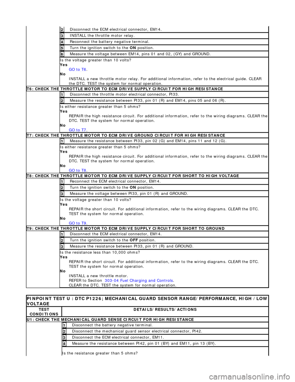
D
isconnect the ECM electrical connector, EM14.
2
IN
STALL the throttle motor relay.
3
R
econnect the battery negative terminal.
4
Turn the ignition swi
tch to the
ON position.
5
Measure the
voltage between EM14, pi
ns 01 and 02, (GY) and GROUND.
6
Is the vol
tage greater than 10 volts?
Yes GO to T6
.
No
INSTALL a new throttle motor relay. For additional information, refer to the electrical guide. CLEAR
the DTC. TEST the system for normal operation.
T
6: CHECK THE THROTTLE MOTOR TO ECM DRIVE SUPPLY CIRCUIT FOR HIGH RESISTANCE
Di
sconnect the throttle motor electrical connector, PI33.
1
Meas
ure the resistance between PI33, pi
n 01 (R) and EM14, pins 05 and 06 (R).
2
Is either resi
stance
greater than 5 ohms?
Yes REPAIR the high resistance circuit. For additional information, refer to the wiring diagrams. CLEAR the
DTC. TEST the system for normal operation.
No GO to T7
.
T
7: CHECK THE THROTTLE MOTOR TO ECM DRIVE GROUND CIRCUIT FOR HIGH RESISTANCE
Meas
ure the resistance between PI33, pin
02 (G) and EM14, pins 11 and 12 (G).
1
Is either resi
stance
greater than 5 ohms?
Yes REPAIR the high resistance circuit. For additional information, refer to the wiring diagrams. CLEAR the
DTC. TEST the system for normal operation.
No GO to T8
.
T
8: CHECK THE THROTTLE MOTOR TO ECM DRIVE SU
PPLY CIRCUIT FOR SHORT TO HIGH VOLTAGE
Re
connect the ECM electrical connector, EM14.
1
Turn the ignition swi
tch to the
ON position.
2
M
easure the voltage between PI33, pin 01 (R) and GROUND.
3
Is the vol
tage greater than 10 volts?
Yes REPAIR the short circuit. For addi tional information, refer to the wiring diagrams. CLEAR the DTC.
TEST the system for normal operation.
No GO to T9
.
T
9: CHECK THE THROTTLE MOTOR TO ECM DRIVE SUPPLY CIRCUIT FOR SHORT TO GROUND
D
isconnect the ECM electrical connector, EM14.
1
Turn the ignition swi
tch to the
OFF position.
2
Meas
ure the resistance between PI33, pin 01 (R) and GROUND.
3
Is
the resistance less than 10,000 ohms?
Yes REPAIR the short circuit. For addi tional information, refer to the wiring diagrams. CLEAR the DTC.
TEST the system for normal operation.
No INSTALL a new throttle motor.
REFER to Section 303
-0
4 Fuel Charging and Controls
.
CLEAR t
he DTC. TEST the system for normal operation.
P
INPOINT TEST U : DTC P1226; MECHANICAL
GUARD SENSOR RANGE/PERFORMANCE, HIGH /LOW
VOLTAGE
TE
ST
CONDITIONS
D
ETAILS/RESULTS/ACTIONS
U1: CHECK T
HE MECHANICAL GUARD SENSE CIRCUIT FOR HIGH RESISTANCE
Di
sconnect the battery negative terminal.
1
Di
sconnect the mechanical guard sensor electrical connector, PI42.
2
D
isconnect the ECM electrical connector, EM11.
3
Me
asure the resistance between PI42, pin 01 (BY) and EM11, pin 13 (BY).
4
Is th
e resistance greater than 5 ohms?
Page 1224 of 2490
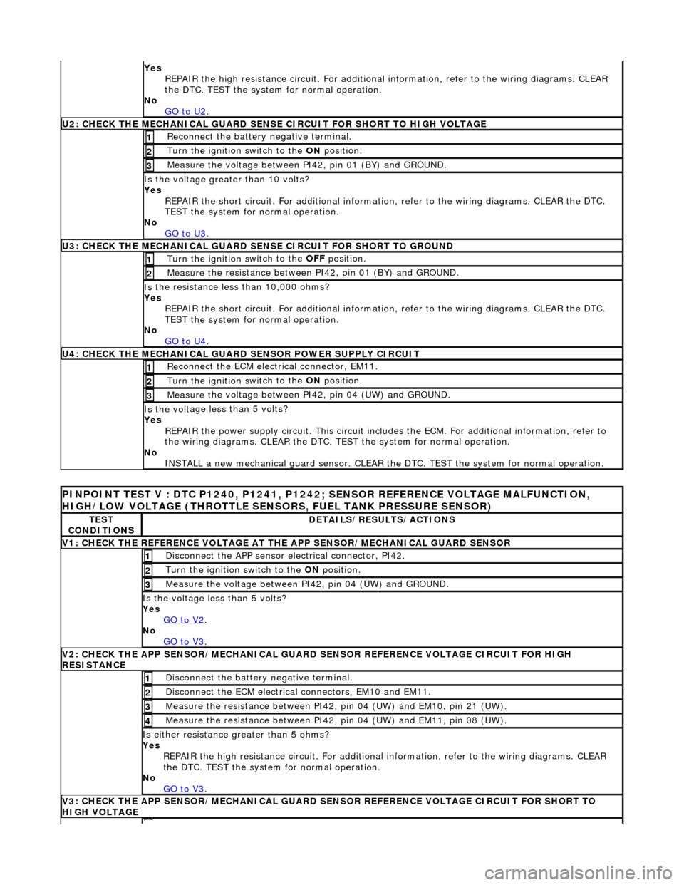
Yes
R
EPAIR the high resistance circui
t. For additional information, refer to the wiring diagrams. CLEAR
the DTC. TEST the system for normal operation.
No GO to U2
.
U2: CHECK T H
E MECHANICAL GUARD SENSE
CIRCUIT FOR SHORT TO HIGH VOLTAGE
Re
connect the battery negative terminal.
1
Turn the ignition swi
t
ch to the ON
position.
2
Measure t
he voltage between PI42, pin 01 (BY) and GROUND.
3
Is the volt
age greater than 10 volts?
Yes REPAIR the short circuit. For addi tional information, refer to the wiring diagrams. CLEAR the DTC.
TEST the system for normal operation.
No GO to U3
.
U3: CHECK T H
E MECHANICAL GUARD SE
NSE CIRCUIT FOR SHORT TO GROUND
Turn the ignition swit
ch to the OFF
position.
1
Measure t
he resistance between PI42, pin 01 (BY) and GROUND.
2
Is
t
he resistance less than 10,000 ohms?
Yes REPAIR the short circuit. For addi tional information, refer to the wiring diagrams. CLEAR the DTC.
TEST the system for normal operation.
No GO to U4
.
U4: CHECK THE MEC H
ANICAL GUARD SENSOR POWER SUPPLY CIRCUIT
Re
conn
ect the ECM electrical connector, EM11.
1
Turn the ignition swi
t
ch to the ON
position.
2
Measure t
he voltage between PI42, pin 04 (UW) and GROUND.
3
Is th
e volt
age less than 5 volts?
Yes
REPAIR the power supply circuit. This circuit includ es the ECM. For additional information, refer to
the wiring diagrams. CLEAR the DTC. TE ST the system for normal operation.
No INSTALL a new mechanical guard sensor. CLEAR the DTC. TEST the system for normal operation.
PINPO
INT TEST V : DTC P1240, P1241, P1242
; SENSOR REFERENCE VOLTAGE MALFUNCTION,
HIGH/LOW VOLTAGE (THROTTLE SENSORS, FUEL TANK PRESSURE SENSOR)
TE S
T
CONDITIONS
D E
TAILS/RESULTS/ACTIONS
V
1
: CHECK THE REFERENCE VOLTAGE AT TH
E APP SENSOR/MECHANICAL GUARD SENSOR
Disc
onnect the APP sensor electrical connector, PI42.
1
Turn the ignition swi
t
ch to the ON
position.
2
Measure the voltage between PI
42,
pin 04 (UW) and GROUND.
3
Is th
e volt
age less than 5 volts?
Yes GO to V2
.
No
GO to V3
.
V2
: CHECK THE APP SENSOR/MECHA
NICAL GUARD SENSOR REFERENCE VOLTAGE CIRCUIT FOR HIGH
RESISTANCE
Di sc
onnect the battery negative terminal.
1
D
i
sconnect the ECM electrical connectors, EM10 and EM11.
2
Me
asure
the resistance between PI42, pin 04 (UW) and EM10, pin 21 (UW).
3
Me
asure
the resistance between PI42, pin 04 (UW) and EM11, pin 08 (UW).
4
Is either resi
stance greater
than 5 ohms?
Yes REPAIR the high resistance circui t. For additional information, refer to the wiring diagrams. CLEAR
the DTC. TEST the system for normal operation.
No GO to V3
.
V3
: CHECK THE APP SENSOR/MECHA
NICAL GUARD SENSOR REFERENCE VOLTAGE CIRCUIT FOR SHORT TO
HIGH VOLTAGE
Page 1225 of 2490
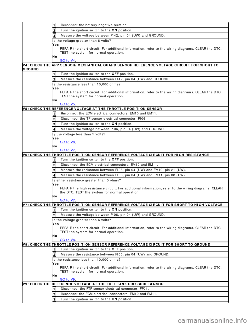
R
econnect the battery negative terminal.
1
Turn the ignition swi
tch to the ON
position.
2
Measure the
voltage between PI
42, pin 04 (UW) and GROUND.
3
Is th
e voltage greater than 6 volts?
Yes REPAIR the short circuit. For addi tional information, refer to the wiring diagrams. CLEAR the DTC.
TEST the system for normal operation.
No GO to V4
.
V
4: CHECK THE APP SENSOR/MECHA
NICAL GUARD SENSOR REFERENCE VOLTAGE CIRCUIT FOR SHORT TO
GROUND
Turn the ignition swi
tch to the
OFF position.
1
Meas
ure the resistance between PI42, pin 04 (UW) and GROUND.
2
Is
the resistance less than 10,000 ohms?
Yes REPAIR the short circuit. For addi tional information, refer to the wiring diagrams. CLEAR the DTC.
TEST the system for normal operation.
No GO to V5
.
V
5: CHECK THE REFERENCE VOLTAGE AT THE THROTTLE POSITION SENSOR
Re
connect the ECM electrical connectors, EM10 and EM11.
1
Disc
onnect the TP sensor electrical connector, PI06.
2
Turn the ignition swi
tch to the ON
position.
3
Measure the
voltage between PI
06, pin 04 (UW) and GROUND.
4
Is th
e voltage less than 5 volts?
Yes GO to V6
.
No
GO to V7
.
V
6: CHECK THE THROTTLE POSITION SENSOR REFE
RENCE VOLTAGE CIRCUIT FOR HIGH RESISTANCE
Turn the ignition swi
tch to the OFF
position.
1
D
isconnect the ECM electrical connectors, EM10 and EM11.
2
Me
asure the resistance between PI06, pin 04 (UW) and EM10, pin 21 (UW).
3
Me
asure the resistance between PI06, pin 04 (UW) and EM11, pin 08 (UW).
4
Is either resi
stance
greater than 5 ohms?
Yes REPAIR the high resistance circui t. For additional information, refer to the wiring diagrams. CLEAR
the DTC. TEST the system for normal operation.
No GO to V7
.
V
7: CHECK THE THROTTLE POSITION SENSOR REFERENCE VOLTAGE CIRCUIT FOR SHORT TO HIGH VOLTAGE
Turn the ignition swi
tch to the ON
position.
1
Measure the
voltage between PI
06, pin 04 (UW) and GROUND.
2
Is th
e voltage greater than 6 volts?
Yes REPAIR the short circuit. For addi tional information, refer to the wiring diagrams. CLEAR the DTC.
TEST the system for normal operation.
No
GO to V8
.
V
8: CHECK THE THROTTLE POSITION SENSOR REFE
RENCE VOLTAGE CIRCUIT FOR SHORT TO GROUND
Turn the ignition swi
tch to the OFF
position.
1
Meas
ure the resistance between PI06, pin 04 (UW) and GROUND.
2
Is
the resistance less than 10,000 ohms?
Yes REPAIR the short circuit. For addi tional information, refer to the wiring diagrams. CLEAR the DTC.
TEST the system for normal operation.
No GO to V9
.
V
9: CHECK THE REFERENCE VOLTAGE AT THE FUEL TANK PRESSURE SENSOR
Di
sconnect the FTP sensor electrical connector, FP01.
1
Re
connect the ECM electrical connectors, EM10 and EM11.
2
Turn the ignition swi
tch to the ON
position.
3