brake sensor JAGUAR X308 1998 2.G Workshop Manual
[x] Cancel search | Manufacturer: JAGUAR, Model Year: 1998, Model line: X308, Model: JAGUAR X308 1998 2.GPages: 2490, PDF Size: 69.81 MB
Page 7 of 2490

206‐07: Powe r Brake Actuation
Specif
ication
Description and Operation
Brake Booster
Removal and Installation
Brake Booster (70.50.17)
Brake Booster and Brake Master Cylinder (70.50.18)
206‐09: Anti ‐Lock Control
Specification
Description and Operation
Anti‐Lock Control
Diagnosis and Testing
Anti‐Lock Control
Removal and Installation
Anti‐Lock Brake System (ABS) Module (70.60.02)
Front Wheel Speed Sensor (70.60.03)
Hydraulic Cont
rol Unit (HCU)
Rear Wheel Speed Sensor (70.60.04)
Wheel Speed Sensor Ring (70.60.25)
211: Steering System
211‐00: Steering System ‐ General Information
Specification
Description and Operation
Steering System
Diagnosis and Testing
Steering Sy
stem
General Procedures
Power Steering System Filling and Bleeding
Power Steering System Flushing (57.15.08)
Power Steering System Vacuum Filling and Bleeding
Steering Gear Centralizing
Page 42 of 2490

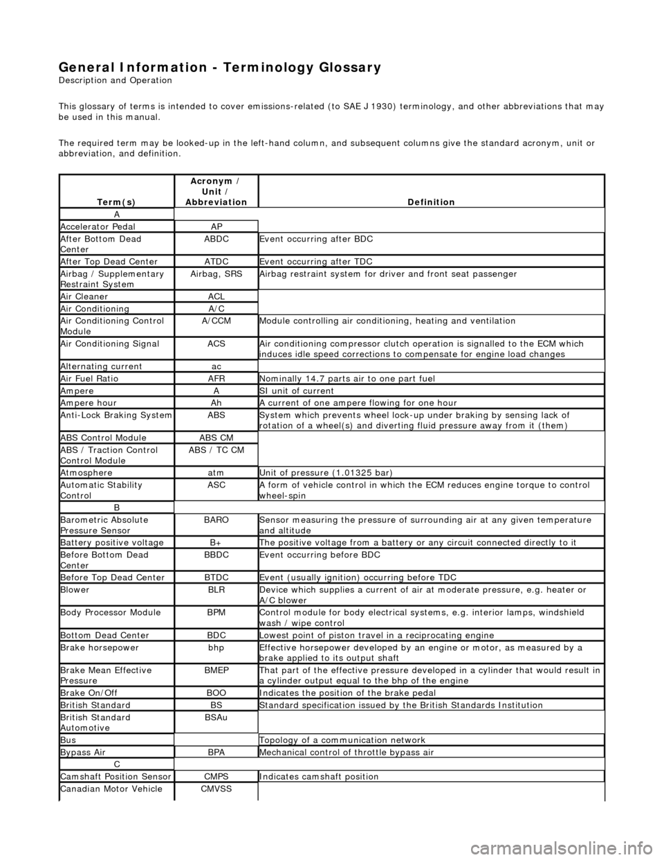
General Information - Terminology Glossary
Description an
d Operation
This glossary of terms is intended to cover emissions-related (to SAE J 1930) term inology, and other abbreviations that may
be used in this manual.
The required term may be looked-up in th e left-hand column, and subsequent columns give the standard acronym, unit or
abbreviation, and definition.
Te rm
(s)
Acr
ony
m /
Unit /
Abbreviation
De fi
nition
A
Accel
e
rator Pedal
AP
Af
ter Botto
m Dead
Center
ABDCEvent occurri ng after
BDC
Af
ter Top Dead CenterATDCEvent occurri ng after
TDC
Ai
rbag /
Supplementary
Restraint System
Airbag, SRSAi rbag restraint system for
dr
iver and front seat passenger
Air Cleane rACL
Air ConditioningA/C
Air Conditioning Con t
rol
Module
A/CCMModule c
ontrolling air conditioning, heating and ventilation
Air Conditioning SignalACSA
i
r conditioning compressor clutch operation is signalled to the ECM which
induces idle speed corrections to co mpensate for engine load changes
Alternating cu
rrent
ac
Ai
r Fuel R
atio
AFRN
omi
nally 14.7 parts air to one part fuel
Ampe
reASI unit of current
Ampere hourAhA current of one ampere
fl
owing for one hour
Anti-Lock Braking SystemABSS
y
stem which prevents wheel lock-up
under braking by sensing lack of
rotation of a wheel(s) and divertin g fluid pressure away from it (them)
ABS Control Mo
dule
ABS CM
ABS /
T
raction Control
Control Module
ABS / T
C CM
Atmosph
e
re
atmU
n
it of pressure (1.01325 bar)
Au
to
matic Stability
Control
ASCA form of vehicle
control
in which the ECM reduces en gine torque to control
wheel-spin
B
Baro me
tric Absolute
Pressure Sensor
BAR OSensor measuring the pressure of surr ou
nding air at any given temperature
and altitude
Bat t
ery positive voltage
B+The posi
ti
ve voltage from a battery or
any circuit connected directly to it
Before Bottom Dead
CenterBBDCEvent occurri ng before BD
C
Before Top Dead
Center
BTD
CEvent (usual ly
ignition) occurring before TDC
Blowe
rBLRDe
vice which supplies a current of air at
moderate pressure, e.g. heater or
A/C blower
Body Processor M
odule
BPMControl modu
le
for body electrical systems, e.g. interior lamps, windshield
wash / wipe control
Bott om D
ead Center
BD
CLowest poin t of piston
travel in a reciprocating engine
Brake hors
epowe
r
bhpEffecti
ve horsepower devel
oped by an
engine or motor, as measured by a
brake applied to its output shaft
Brake Mean Effective
Pres sureBME PThat p
art of the effective
pressure developed in a cyli nder that would result in
a cylinder output equal to the bhp of the engine
Brake On/ O
ff
BOOIn
dic
ates the position of the brake pedal
Br
it
ish Standard
BSStan
dar
d specification issued by the British Standards Institution
Br
it
ish Standard
Automotive
BSAu
BusTopology of a commu n
ication network
Bypass
AirBPAMechanica l
control of throttle bypass air
C
Camshaft Posit
i
on Sensor
CMPSIndi
cat
es camshaft position
Canadian Motor
V
ehicle
CMVSS
Page 67 of 2490

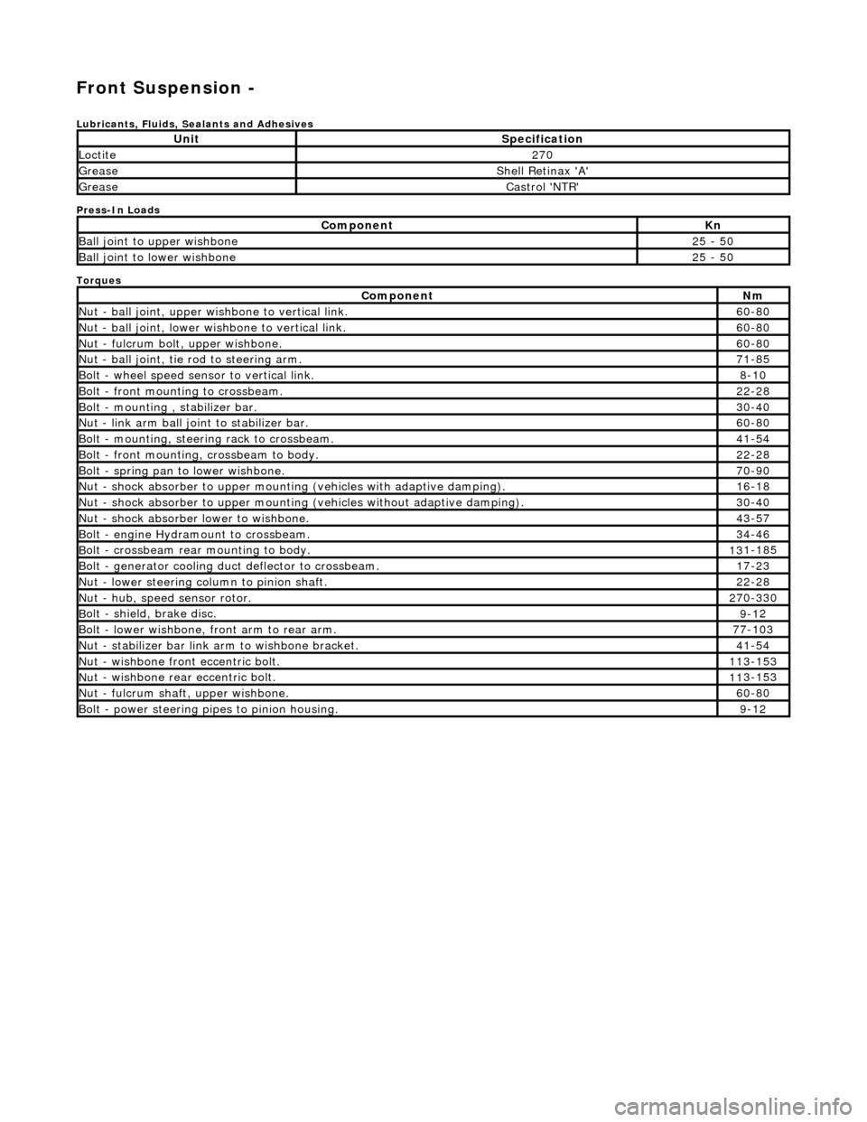
Front Suspension -
Lubri
cants, Fluids, Sealants and Adhesives
Press-In Loads
Torques
UnitS
pecification
Loctite27
0
Greas
e
Shell Retin
ax 'A'
Greas
e
Castro
l 'NTR'
Com
ponent
Kn
Ball join
t to upper wishbone
25
- 50
B
all joint to lower wishbone
25
- 50
Com
ponent
Nm
N
ut - ball joint, upper wishbone to vertical link.
60
-80
N
ut - ball joint, lower wishbone to vertical link.
60
-80
Nu
t - fulcrum bolt, upper wishbone.
60
-80
N
ut - ball joint, tie rod to steering arm.
71
-85
Bol
t - wheel speed sensor to vertical link.
8-1
0
Bol
t - front mounting to crossbeam.
22
-28
Bolt
- mounting , stabilizer bar.
30
-40
N
ut - link arm ball joint to stabilizer bar.
60
-80
Bolt
- mounting, steering rack to crossbeam.
41
-54
B
olt - front mounting, crossbeam to body.
22
-28
Bol
t - spring pan to lower wishbone.
70
-90
N
ut - shock absorber to upper mounting
(vehicles with adaptive damping).
16
-18
Nu
t - shock absorber to upper mounting (vehicles without adaptive damping).
30
-40
N
ut - shock absorber lower to wishbone.
43
-57
B
olt - engine Hydramount to crossbeam.
34
-46
B
olt - crossbeam rear mounting to body.
13
1-185
Bol
t - generator cooling du
ct deflector to crossbeam.
17
-23
N
ut - lower steering column to pinion shaft.
22
-28
N
ut - hub, speed sensor rotor.
27
0-330
B
olt - shield, brake disc.
9-1
2
Bol
t - lower wishbone, front arm to rear arm.
77
-103
Nu
t - stabilizer bar link arm to wishbone bracket.
41
-54
N
ut - wishbone front
eccentric bolt.
11
3-153
Nu
t - wishbone rear
eccentric bolt.
11
3-153
N
ut - fulcrum shaft, upper wishbone.
60
-80
Bolt -
power steering pi
pes to pinion housing.
9-1
2
Page 89 of 2490

Inst
all sensor bolt an
d tighten to 8-10Nm.
22
.
Connect wheel speed sensor harness.
1. Connect wheel speed sensor harness to sensor.
2. Using new tiestraps secure wheel speed sensor harness to upper wishbone.
23
.
Install brake calipers.
R
emove tie supporting brake caliper.
1. Install caliper on carrier.
2. Install guide pins.
3. Install guide pin dust caps.
4. Install caliper spring clip.
24. Install road wheel. Re fer to Section 100-02.
25. Raise vehicle, remove stands and lower vehicle onto road
wheels.
26
.
Ensuring graduation mark remains aligned, finally tighten
wishbone rear eccentric bolt to 113-153Nm.
27. Check wheel alignment and if necessary adjust. Refer to
57.65.01.
Page 103 of 2490

2.
Using new tiestraps secure wheel speed sensor
harness to upper wishbone.
25
.
Install brake calipers.
R
emove tie supporting brake caliper.
1. Install caliper on carrier.
2. Install guide pins and tighten to 25-30Nm.
3. Install guide pin dust caps.
4. Install caliper spring clip.
26
.
Position and partially tighten wishbone rear eccentric bolt.
R
otate eccentric bolt to align large graduation with mark
made during removal.
27
.
Position and partially tighten wishbone front eccentric bolt.
R
otate eccentric bolt to align large graduation with mark
made during removal.
P
artially tighten bolt.
28. Fit road wheel. Refer to Section 100-02.
29. Raise vehicle, remove stands and lower vehicle onto road
wheels.
30. Ensuring graduation mark remains aligned, finally tighten
wishbone rear eccentric bolt to 113-153Nm.
Page 171 of 2490

Rear
Suspension - Rear Susp
ension and Axle Assembly
Re
moval and Installation
Remov
al
1.
CAUTI
ON: Replacement of nuts and bolts: Various
thread-locking devices are used on nuts and bolts throughout the
vehicle. These devices restrict the number of times a nut or bolt
can be used.
For additional informat ion, refer to Section 100
-0
0 General
Informati
on
.
R
aise the rear of the vehicle
and support on axle stands.
For additional informat ion, refer to Section 100
-0
2 Jacking and
Liftin
g
.
2.
R
emove the rear wheels.
For additional informat ion, refer to Section 204
-04
Wheels and
Tire
s
.
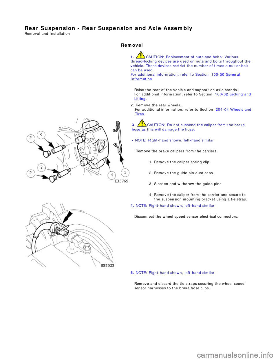
3. CAUTI
ON: Do not suspend the caliper from the brake
hose as this will damage the hose.
• NOTE: Right-hand shown, left-hand similar
Remove the brake calipers from the carriers.
1. Remove the caliper spring clip.
2. Remove the guide pin dust caps.
3. Slacken and withdr aw the guide pins.
4. Remove the caliper from the carrier and secure to the suspension mounting bracket using a tie strap.
4. NOTE
: Right-hand shown, left-hand similar
Disconnect the wheel speed sensor electrical connectors.
5. NOTE: Right-hand shown, left-hand similar
Remove and discard th e tie straps securing the wheel speed
sensor harnesses to the brake hose clips.
Page 179 of 2490

18
.
Install the brake caliper on to the carrier.
1. Position the caliper asse mbly on to the carrier.
2. Install the guide pins and tighten to 25-30 Nm.
3. Install the dust caps.
4. Install the brake caliper spring clip.
19
.
Connect the wheel speed sensor electrical connector.
20
.
Using a new tie strap, secure the wheel speed sensor harness
to the brake hose clip.
21. Install the rear wheels.
For additional informat ion, refer to Section 204
-04
Wheels and
Tire
s
.
22
.
Remove the axle stands and lower the vehicle.
For additional informat ion, refer to Section 100
-0
2 Jacking and
Liftin
g
.
23
.
Check and adjust the rear whee l alignment as necessary.
For additional informat ion, refer to Section 204
-00
Suspension
Sy
stem
- General
Information
.
Page 180 of 2490

Rear Su
spension - Rear Shock Absorber
Re
mo
val and Installation
Remov
a
l
S
p
ecial Tool(s)
Spri
ng C
ompressors
204-179 (JD 199)
Spri ng Re
taining straps
204-179-1 (JD 199-1)
1. CAUTION: Replacement of nuts and bolts: Various
thread-locking devices are used on nuts and bolts throughout the
vehicle. These devices restrict the number of times a nut or bolt
can be used.
For additional informat ion, refer to Section 100
-00
General
Informati
o
n
.
R a
ise the rear of the vehicle
and support on axle stands.
For additional informat ion, refer to Section 100
-02
Jacking and
Liftin
g.
2. Re
move the relevant rear wheel.
For additional informat ion, refer to Section 204
-04 W
heels and
Tire
s.
3. CAUTIO
N: Do not suspend the caliper from the brake
hose as this will damage the hose.
Remove the brake caliper from the carrier.
1. Remove the caliper spring clip.
2. Remove the guide pin dust caps.
3. Slacken and withdr aw the guide pins.
4. Remove the caliper from the carrier and secure to the suspension mounting bracket using a tie strap.
4. Disc
onnect the wheel speed sensor electrical connector.
Page 181 of 2490

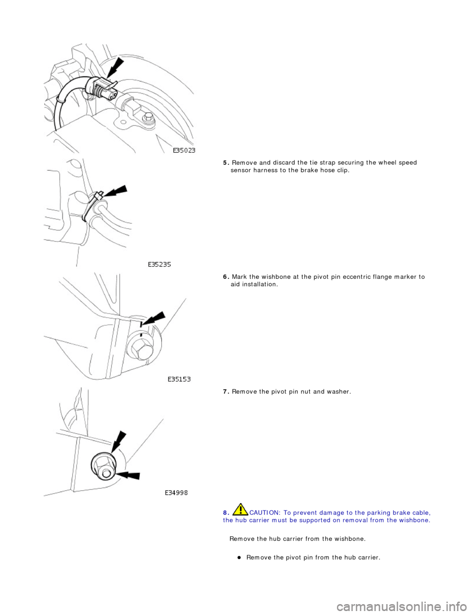
5. Remove an
d discard the tie st
rap securing the wheel speed
sensor harness to the brake hose clip.
6. Mark the wi
shbone at the pivot
pin eccentric flange marker to
aid installation.
7. Remove the
pivot pin nut and washer.
8. CAUTION: To prevent damage to the parking brake cable,
the hub carrier must be supported on removal from the wishbone.
R
emove the hub carrie
r from the wishbone.
R
emove the pivot pin from the hub carrier.
Page 190 of 2490

22. R
elease the tie strap securing the brake caliper to the
suspension mounting bracket.
23 . Install
the brake caliper on to the carrier.
1. Position the caliper asse mbly on to the carrier.
2. Install the guide pins and tighten to 25-30 Nm.
3. Install the dust caps.
4. Install the brake caliper spring clip.
24 . Conne
ct the wheel speed sensor electrical connector.
25 . U
sing a new tie strap, secure the wheel speed sensor harness
to the brake hose clip.
26. Install the rear wheel.
For additional informat ion, refer to Section 204
-04 W
heels and
Tire
s.
27 .
Remove the
axle stands
and lower the vehicle.
For additional informat ion, refer to Section 100
-02
Jacking and
Liftin
g.