key JAGUAR X308 1998 2.G Repair Manual
[x] Cancel search | Manufacturer: JAGUAR, Model Year: 1998, Model line: X308, Model: JAGUAR X308 1998 2.GPages: 2490, PDF Size: 69.81 MB
Page 2388 of 2490
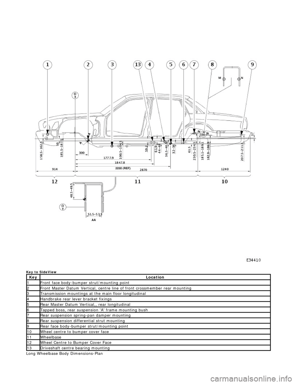
Key to SideView
Long Wheelbase Body Dimensions-Plan
KeyLocation
1Front face body-bumper strut/mounting point
2Front Master Datum Vertical, centre line of front crossmember rear mounting
3Transmission mountings at the main floor longitudinal
4Handbrake rear lever bracket fixings
5Rear Master Datum Vertical,, rear longitudinal
6Tapped boss, rear suspensi on 'A' frame mounting bush
7Rear suspension spring-pan damper mounting
8Rear suspension differential strut mounting
9Rear face body-bumper strut/mounting point
10Wheel centre to bumper cover face
11Wheelbase
12Wheel Centre to Bumper Cover Face
13Driveshaft centre bearing mounting
Page 2389 of 2490
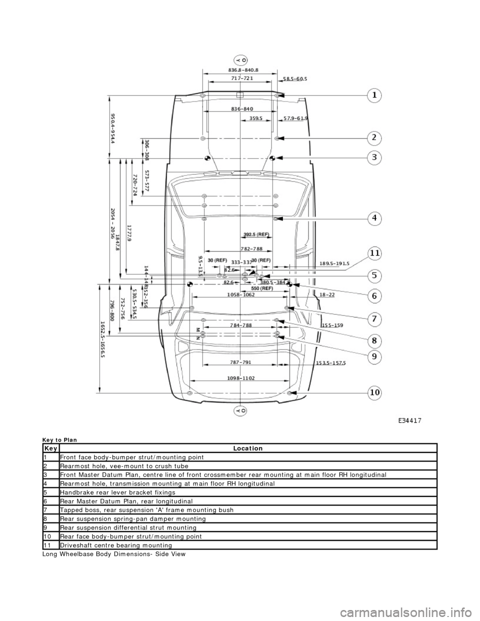
Key to Plan
Long Wheelbase Body Dimensions- Side View
KeyLocation
1Front face body-bumper strut/mounting point
2Rearmost hole, vee-mount to crush tube
3Front Master Datum Plan, centre line of front crossmember rear mount ing at main floor RH longitudinal
4Rearmost hole, transmission mounting at main floor RH longitudinal
5Handbrake rear lever bracket fixings
6Rear Master Datum Plan, rear longitudinal
7Tapped boss, rear suspension 'A' frame mounting bush
8Rear suspension spring-pan damper mounting
9Rear suspension differential strut mounting
10Rear face body-bumper strut/mounting point
11Driveshaft centre bearing mounting
Page 2390 of 2490

Key to SideView
KeyLocation
1Front face body-bumper strut/mounting point
2Front Master Datum Vertical, centre line of front crossmember rear mounting
3Transmission mountings at the main floor longitudinal
4Handbrake rear lever bracket fixings
5Rear Master Datum Vertical,, rear longitudinal
6Tapped boss, rear suspensi on 'A' frame mounting bush
7Rear suspension spring-pan damper mounting
8Rear suspension differential strut mounting
9Rear face body-bumper strut/mounting point
10Wheel centre to bumper cover face
11Wheelbase
12Wheel Centre to Bumper Cover Face
13Driveshaft centre bearing mounting
Page 2411 of 2490
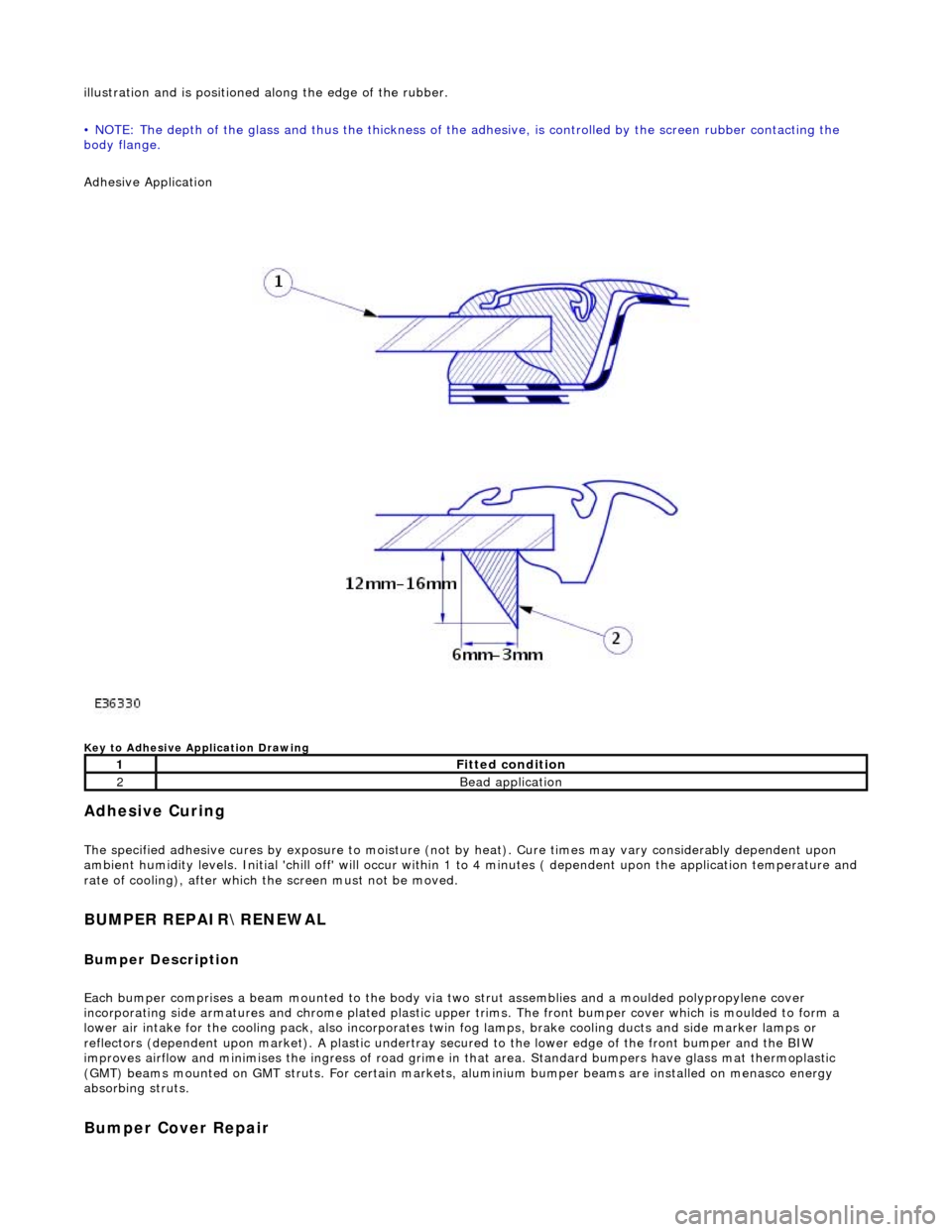
illustration and is positioned along the edge of the rubber.
• NOTE: The depth of the glass and thus the thickness of the ad hesive, is controlled by the screen rubber contacting the
body flange.
Adhesive Application
Key to Adhesive Application Drawing
Adhesive Curing
The specified adhesive cures by exposure to moisture (not by heat). Cure times may vary considerably dependent upon
ambient humidity levels. Initial 'chill off' will occur within 1 to 4 minutes ( dependent upon the application temperature and
rate of cooling), after which the screen must not be moved.
BUMPER REPAIR\RENEWAL
Bumper Description
Each bumper comprises a beam mounte d to the body via two strut assemblies and a moulded polypropylene cover
incorporating side armatures and chrome plated plastic upper trims. The front bumper cover which is moulded to form a
lower air intake for the cooling pack, also incorporates twin fog lamps, brake cooling ducts and side marker lamps or
reflectors (dependent upon market). A plastic undertray secured to the lower edge of the front bumper and the BIW
improves airflow and minimises the ingres s of road grime in that area. Standard bumpers have glass mat thermoplastic
(GMT) beams mounted on GMT struts. For certain markets, aluminium bumper beams are installed on menasco energy
absorbing struts.
Bumper Cover Repair
1Fitted condition
2Bead application
Page 2439 of 2490
Uni-Body, Subframe and Mounting System - Front Axle Crossmember
Front Bushing
Removal and Installation
Removal
CAUTION: Replacement of nuts and bolts: Various thread-locking devices are used on nuts and bolts throughout the
vehicle. These devices restrict the number of times a nut or bolt can be used. See Section 100-00 for information.
Special Tool(s)
Engine Support Beam
303-021 (MS 53D)
Front Camber Tie-down Link
204-114 (JD 133)
1. Position vehicle on a four-post lift.
2. Remove ignition key and en gage steering column lock.
3. Open hood to service position, and fit covers to fenders.
4. Remove battery cover and disc onnect ground cable from
battery terminal. Refer to 86.15.19.
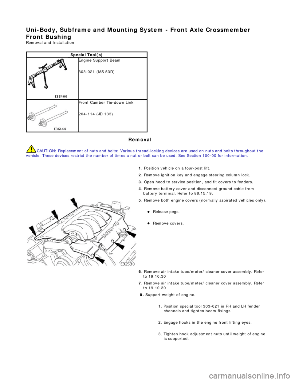
5. Remove both engine covers (nor mally aspirated vehicles only).
Release pegs.
Remove covers.
6. Remove air intake tube/meter/ cleaner cover assembly. Refer
to 19.10.30
7. Remove air intake tube/meter/ cleaner cover assembly. Refer
to 19.10.30
8. Support weight of engine.
1. Position special tool 303-021 in RH and LH fender channels and tighte n beam fixings.
2. Engage hooks in the en gine front lifting eyes.
3. Tighten hook adjustment nuts until weight of engine is supported.
Page 2450 of 2490
Uni-Body, Subframe and Mounting System - Front Axle Crossmember
Front Bushing Heat Shield
Removal and Installation
Removal
CAUTION: Replacement of nuts and bolts: Various thread-locking devices are used on nuts and bolts throughout the
vehicle. These devices restrict the number of times a nut or bolt can be used. See Section 100-00 for information.
Special Tool(s)
Engine Support Beam
303-021 (MS 53D)
Front Camber Tie-down Link
204-114 (JD 133)
1. Position vehicle on a four-post lift.
2. Remove ignition key and en gage steering column lock.
3. Open hood to service position, and fit covers to fenders.
4. Remove battery cover and disc onnect ground cable from
battery terminal. Refer to section 86.15.15.
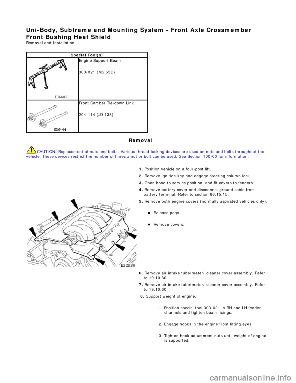
5. Remove both engine covers (nor mally aspirated vehicles only).
Release pegs.
Remove covers.
6. Remove air intake tube/meter/ cleaner cover assembly. Refer
to 19.10.30
7. Remove air intake tube/meter/ cleaner cover assembly. Refer
to 19.10.30
8. Support weight of engine.
1. Position special tool 303-021 in RH and LH fender channels and tighte n beam fixings.
2. Engage hooks in the en gine front lifting eyes.
3. Tighten hook adjustment nuts until weight of engine is supported.