key JAGUAR X308 1998 2.G Owner's Guide
[x] Cancel search | Manufacturer: JAGUAR, Model Year: 1998, Model line: X308, Model: JAGUAR X308 1998 2.GPages: 2490, PDF Size: 69.81 MB
Page 2099 of 2490
Exterior Trim and Ornamentation - Exterior Trim
Description and Operation
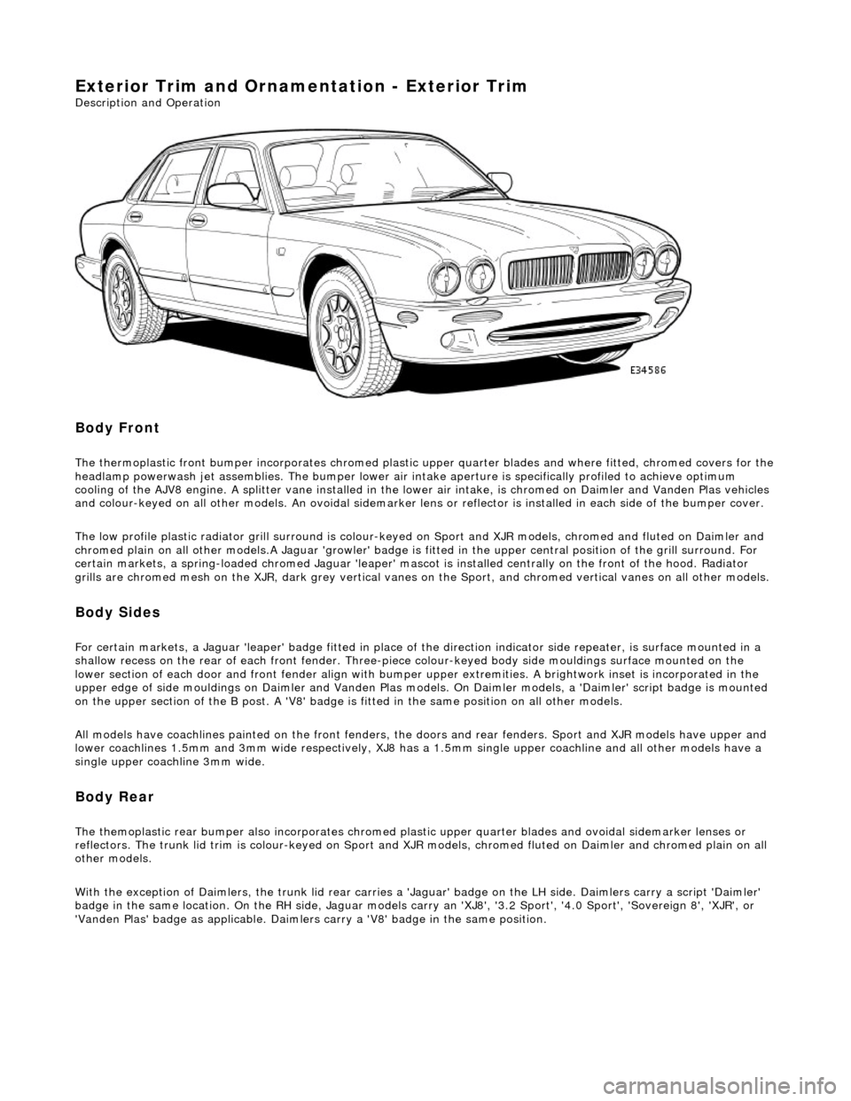
Body Front
The thermoplastic front bumper incorporates chromed plastic upper quarter blades and where fitted, chromed covers for the headlamp powerwash jet assemblie s. The bumper lower air intake aperture is specifically profiled to achieve optimum
cooling of the AJV8 engine. A splitter vane installed in the lowe r air intake, is chromed on Daimler and Vanden Plas vehicles
and colour-keyed on all other models. An ov oidal sidemarker lens or reflector is installed in each side of the bumper cover.
The low profile plastic radiator grill surround is colour-keyed on Sport and XJR mo dels, chromed and fluted on Daimler and
chromed plain on all other models .A Jaguar 'growler' badge is fitted in the upper central positi on of the grill surround. For
certain markets, a spring-loaded chromed Ja guar 'leaper' mascot is installed centrally on the front of the hood. Radiator
grills are chromed mesh on the XJR, dark grey vertical vanes on the Sport, and chromed ve rtical vanes on all other models.
Body Sides
For certain markets, a Jaguar 'l eaper' badge fitted in place of the direction indicator side re peater, is surface mounted in a
shallow recess on the rear of each fro nt fender. Three-piece colour-keyed body side mouldings surface mounted on the
lower section of each door and front fender align with bumper upper extremities. A brightwork inset is incorporated in the
upper edge of side mouldings on Daimler and Vanden Plas models. On Daimler models, a 'Daimler' script badge is mounted
on the upper section of the B post. A 'V8' badge is fitted in the same position on all other models.
All models have coachlines painted on th e front fenders, the doors and rear fender s. Sport and XJR models have upper and
lower coachlines 1.5mm an d 3mm wide respectively, XJ8 has a 1.5mm single upper coachline and all other models have a
single upper coachline 3mm wide.
Body Rear
The themoplastic rear bumper also inco rporates chromed plastic upper quarter blades and ovoi dal sidemarker lenses or
reflectors. The trunk lid trim is colour-keyed on Sport and XJ R models, chromed fluted on Daimler and chromed plain on all
other models.
With the exception of Daimlers, the trunk lid rear carries a 'Jaguar' badge on the LH side. Daimlers carry a script 'Daimler'
badge in the same location. On th e RH side, Jaguar models carry an 'XJ8', '3.2 Sport', '4.0 Sport', 'Sovereign 8', 'XJR', or
'Vanden Plas' badge as applic able. Daimlers carry a 'V8' badge in the same position.
Page 2111 of 2490

Rear View Mirrors - Rear View Mirrors
Description and Operation
Interior Rear View Mirror
The interior rear view mirror is an elec trochromic unit that automatically darken s to prevent glare from following vehicle
lights. This automatic function is selected by pressing the switch at the bottom of the mirror. Pressing the switch again
cancels this function. An LE D then illuminates when automatic dipping is operative.
A Night Sentinel light sensing unit also incorporated in the mi rror casing, provides for automatic control of the vehicle lights.
Door Rear View Mirrors
The door mirrors are cheater mounted, colo r-keyed units, remote electrically adjustable and heated. Adjustment of both
mirrors is carried out from the driver's door switchpack. A slider switch selects the mirror to be adjusted, and a disc switch
adjusts the selected mirror to the required position.
Page 2161 of 2490

6. Using 44 hog rings, secure co ver to outer edges of frame.
7. Position cover inside armrest ap erture and secure on the eight
armrest aperture tangs.
8. CAUTION: The apertures in the foam are over-size and
must not be used for guidance wh en cutting seat belt escutcheon
apertures in cover.
Using a suitable knife, carefully cut around headrest support
box and seat belt apertures.
9. With keyways facing forward, fit headrest guide tubes in
support boxes.
10. Ensure that lower segmented end of each headrest guide
tube fully seats on lower flange of support box.
Page 2174 of 2490

6. Push trim upwards to release keyhole aperture from squab
fixing and partially withdraw trim for access.
7. Slacken and remove seat belt lower anchor securing bolt.
8. Carefully withdraw seat belt and anchor plate through trim
aperture and escutcheon.
9. Remove side trim panel from vehicle.
10. Slacken and remove the seat squab outer securing bolt.
11. Slacken and remove the seat squab inner securing bolt.
Page 2175 of 2490

Installation
12. Disconnect seat motor and squab heater harness multiplugs.
13. Slacken and remove four bolts securing seat frame to floor
and remove seat from vehicle.
1. Position seat in vehi cle and fit but do not tighten four bolts
securing frame to floor.
2. Fit and fully tighten the two bolt s securing squab frame to rear
panel.
3. Fully tighten bolts securing frame to floor.
4. Connect seat motor and squab heater harness multiplugs.
5. Position side trim panel and carefully pass seat belt lower
anchor through escutcheon and trim aperture.
6. Fit and tighten seat belt anchor securing bolt.
7. Position side trim and push do wnwards to engage keyhole on
squab outer fixing.
8. Position trim lower end over st ud and fit and fully seat new
scrivet.
9. Position seat cushion for access and connect cushion heater
harness multiplug.
10. Push seat cushion rearwards to engage it in rear securing
lugs.
Page 2179 of 2490
Glass, Frames and Mechanisms - Glass, Frames and Mechanisms
Description and Operation
Fixed Glass
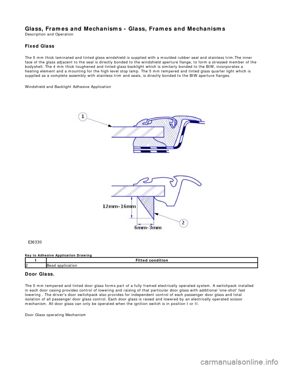
The 5 mm thick laminated and tinted glas s windshield is supplied with a moulded rubber seal and stainless trim.The inner
face of the glass adjacent to the seal is directly bonded to the windshield aperture flange, to form a stressed member of the
bodyshell. The 4 mm thick toughened and tinted glass backlight which is similarly bonded to the BIW, incorporates a
heating element and a mounting for the high level stop lamp. The 5 mm tempered and tinted glass quarter light which is
supplied as a complete assembly with stainless trim and seals, is directly bonded to the BIW aperture flanges.
Windshield and Backlight Adhesive Application
Key to Adhesive Application Drawing
Door Glass.
The 5 mm tempered and tinted door glass forms part of a fully framed electrically operated system. A switchpack installed
in each door casing provides control of lowering and raising of that particular d oor glass with additional 'one-shot' fast
lowering . The driver's door switchpack also provides for independent control of each passenger door glass and total
isolation of all passenger door glass control. Each door glas s is raised and lowered by an electrically operated scissor
mechanism. All door glass can only be operated wh en the ignition switch is in position I or II.
Door Glass operating Mechanism
1Fitted condition
2Bead application
Page 2219 of 2490
Instrument Panel and Console - Instrument Panel and Instrument Panel
Console
Description and Operation
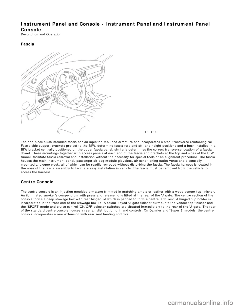
Fascia
The one-piece slush-moulded fascia has an injection-moulded ar mature and incorporates a steel transverse reinforcing rail.
Fascia side support brackets pre-set to th e BIW, determine fascia fore and aft, and height position s and a bush installed in a
BIW bracket centrally positioned on the upper fascia panel, similarly determines the correct transverse location of a fascia
dowel. These mountings together with access panels at each en d of the fascia and brackets at the top and sides of the BIW
tunnel, facilitate fascia removal and instal lation without the necessity for special tools or an alignment procedure. The fasci a
houses the main instrument panel, pass enger air bag module glovebox, air conditioning outlet vents and a centrally
mounted analogue clock, all of which can be readily removed wi thout disturbing the fascia. The fascia harness is located in
the nose of the fascia assembly to facilitate easy installati on in vehicle. The fascia must be removed from the vehicle to
access the harness.
Centre Console
The centre console is an injection moulded armature trimmed in matching ambla or leather with a wood veneer top finisher.
An iluminated smoker's compendium with pr ess and release lid is fitted at the rear of the 'J' gate. The centre section of the
console forms a deep stowage box with rear hinged lid which is padded to form a central arm rest. A hinged cup holder is
incorporated in the front end of the stowage box lid. A colour-keyed 'J' gate finisher surmounts the veneer top finisher and
the 'SPORT' mode and cruise control 'ON/OFF' selector switches are situated immediately to the rear of the 'J' gate. The rear
of the standard centre console houses a re ar air distribution grill and controls. On Daimler and 'Super 8' models, the centre
console incorporates a rear extensio n with rear seat heating controls.
Page 2229 of 2490

Instrument Panel and Console - Floor Console Finish Panel
Removal and Installation
Removal
1. Apply handbrake and turn ignition key to II.
2. Depress brake pedal, move gear selector to position N and turn
ignition key to O.
3. Remove battery cover and di sconnect cable from earth
terminal. Refer to Section 86.15.19.
4. Remove 'J 'gate finisher. Refer to 76.25.24.
5. Slacken and remove the two nuts and two screws securing
the retaining panel.
6. Position retaining panel for access, disconnect SPORT mode
and cruise control ON/OFF swit ch multiplugs and remove
retaining panel complete with switches.
7. Remove and discard bushes from retaining plate.
8. Carefully withdraw veneer pane l, releasing front locating
tongue from upper slot in comsole.
Page 2239 of 2490
Instrument Panel and Console - Instrument Cluster Finish Panel
Removal and Installation
Removal
Installation
1.
Turn ignition key to position II.
2. Move steering column to lowest and fully extended position.
3. Turn ignition key to position 'O'.
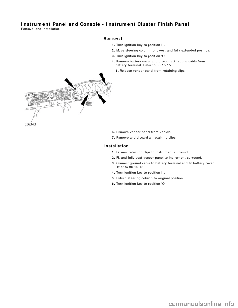
4. Remove battery cover and disc onnect ground cable from
battery terminal. Refer to 86.15.15.
5. Release veneer panel from retaining clips.
6. Remove veneer panel from vehicle.
7. Remove and discard all retaining clips.
1. Fit new retaining clips to instrument surround.
2. Fit and fully seat veneer pa nel to instrument surround.
3. Connect ground cable to battery terminal and fit battery cover.
Refer to 86.15.15.
4. Turn ignition key to position II.
5. Return steering column to original position.
6. Turn ignition key to position 'O'.
Page 2240 of 2490
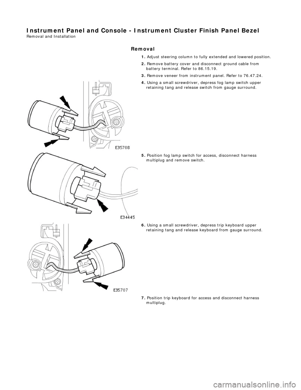
Instrument Panel and Console - Instrument Cluster Finish Panel Bezel
Removal and Installation
Removal
1. Adjust steering column to full y extended and lowered position.
2. Remove battery cover and disc onnect ground cable from
battery terminal. Refer to 86.15.19.
3. Remove veneer from instrument panel. Refer to 76.47.24.
4. Using a small screwdriver, de press fog lamp switch upper
retaining tang and release sw itch from gauge surround.
5. Position fog lamp switch fo r access, disconnect harness
multiplug and remove switch.
6. Using a small screwdriver, depress trip keyboard upper
retaining tang and release ke yboard from gauge surround.
7. Position trip keyboard for ac cess and disconnect harness
multiplug.