body mounting JAGUAR X308 1998 2.G Manual PDF
[x] Cancel search | Manufacturer: JAGUAR, Model Year: 1998, Model line: X308, Model: JAGUAR X308 1998 2.GPages: 2490, PDF Size: 69.81 MB
Page 2442 of 2490

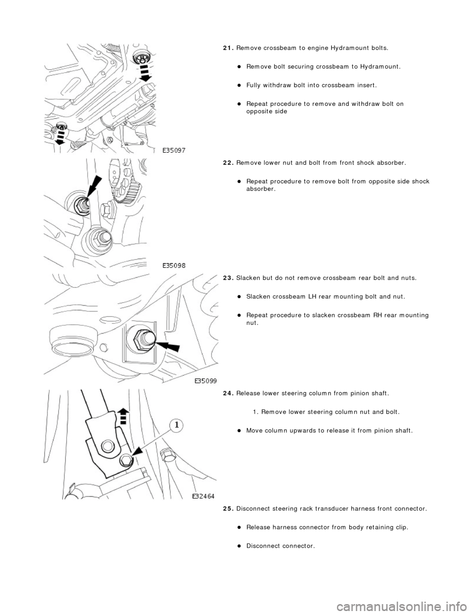
21. Remove crossbeam to engi ne Hydramount bolts.
Remove bolt securing crossbeam to Hydramount.
Fully withdraw bolt into crossbeam insert.
Repeat procedure to remove and withdraw bolt on
opposite side
22. Remove lower nut and bolt from front shock absorber.
Repeat procedure to remove bo lt from opposite side shock
absorber.
23. Slacken but do not remove crossbeam rear bolt and nuts.
Slacken crossbeam LH rear mounting bolt and nut.
Repeat procedure to slacken crossbeam RH rear mounting
nut.
24. Release lower steering column from pinion shaft.
1. Remove lower steering column nut and bolt.
Move column upwards to release it from pinion shaft.
25. Disconnect steering rack transducer harness front connector.
Release harness connector from body retaining clip.
Disconnect connector.
Page 2444 of 2490

Installation
30. CAUTION: Slowly lower the crossbeam just sufficient to
provide the required clearance. Lowering the crossbeam
excessively can damage the suspension and steering pipes.
Carefully lower crossbeam to provide sufficient clearance
between front mounting and body.
31. Remove crossbeam front mounting.
Remove front mounting heatshield.
Remove four bolts securing mounting to crossbeam.
1. Install crossbeam front mounting.
Position new mounting on crossbeam.
Install four bolts securing mounting to crossbeam and
tighten to 22-28Nm.
Install front mounting heatshield.
2. NOTE: It may be necessary to use a hammer and drift to
finally align new mounting with body location.
Carefully raise crossbeam assembly into position.
Ensure that dowels of both crossbeam mountings are
Page 2445 of 2490

correctly seated in body locations.
3. Ensure that both engine hydram ounts are correctly seated in
crossbeam locations.
4. From engine compartment, install but do not tighten
crossbeam front RH bolts.
5. From engine compartment, install crossbeam front LH bolts
and tighten to 22-28Nm.
6. Install power steering fluid reservoir.
Position reservoir on mounting bracket.
Install reservoir securi ng nuts and bolts.
Page 2447 of 2490

3. Remove special tool 303-021 from fender channel.
11. Install crossbeam to engine Hydramount bolts.
Install bolt securing Hydramou nt to crossbeam and tighten to 34-46Nm.
Repeat procedure to install crossbeam opposite side bolt.
12. Tighten rear mounting bolt and nut to 131-185 Nm.
Repeat procedure to tighten opposite side rear mounting
bolt and nut.
13. Connect steering rack transducer harness front connector.
Connect steering ha rness connector.
Install harness connector on body retaining clip.
14. Slacken adjuster nut and remove camber tie down tool 204-
114 from suspension.
Repeat procedure to remove tie down tool from opposite
side.
Page 2450 of 2490

Uni-Body, Subframe and Mounting System - Front Axle Crossmember
Front Bushing Heat Shield
Removal and Installation
Removal
CAUTION: Replacement of nuts and bolts: Various thread-locking devices are used on nuts and bolts throughout the
vehicle. These devices restrict the number of times a nut or bolt can be used. See Section 100-00 for information.
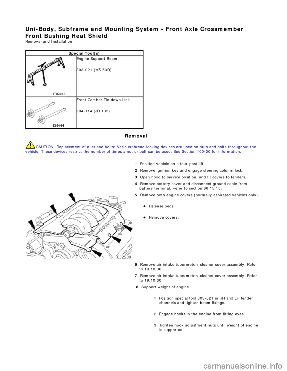
Special Tool(s)
Engine Support Beam
303-021 (MS 53D)
Front Camber Tie-down Link
204-114 (JD 133)
1. Position vehicle on a four-post lift.
2. Remove ignition key and en gage steering column lock.
3. Open hood to service position, and fit covers to fenders.
4. Remove battery cover and disc onnect ground cable from
battery terminal. Refer to section 86.15.15.
5. Remove both engine covers (nor mally aspirated vehicles only).
Release pegs.
Remove covers.
6. Remove air intake tube/meter/ cleaner cover assembly. Refer
to 19.10.30
7. Remove air intake tube/meter/ cleaner cover assembly. Refer
to 19.10.30
8. Support weight of engine.
1. Position special tool 303-021 in RH and LH fender channels and tighte n beam fixings.
2. Engage hooks in the en gine front lifting eyes.
3. Tighten hook adjustment nuts until weight of engine is supported.
Page 2453 of 2490

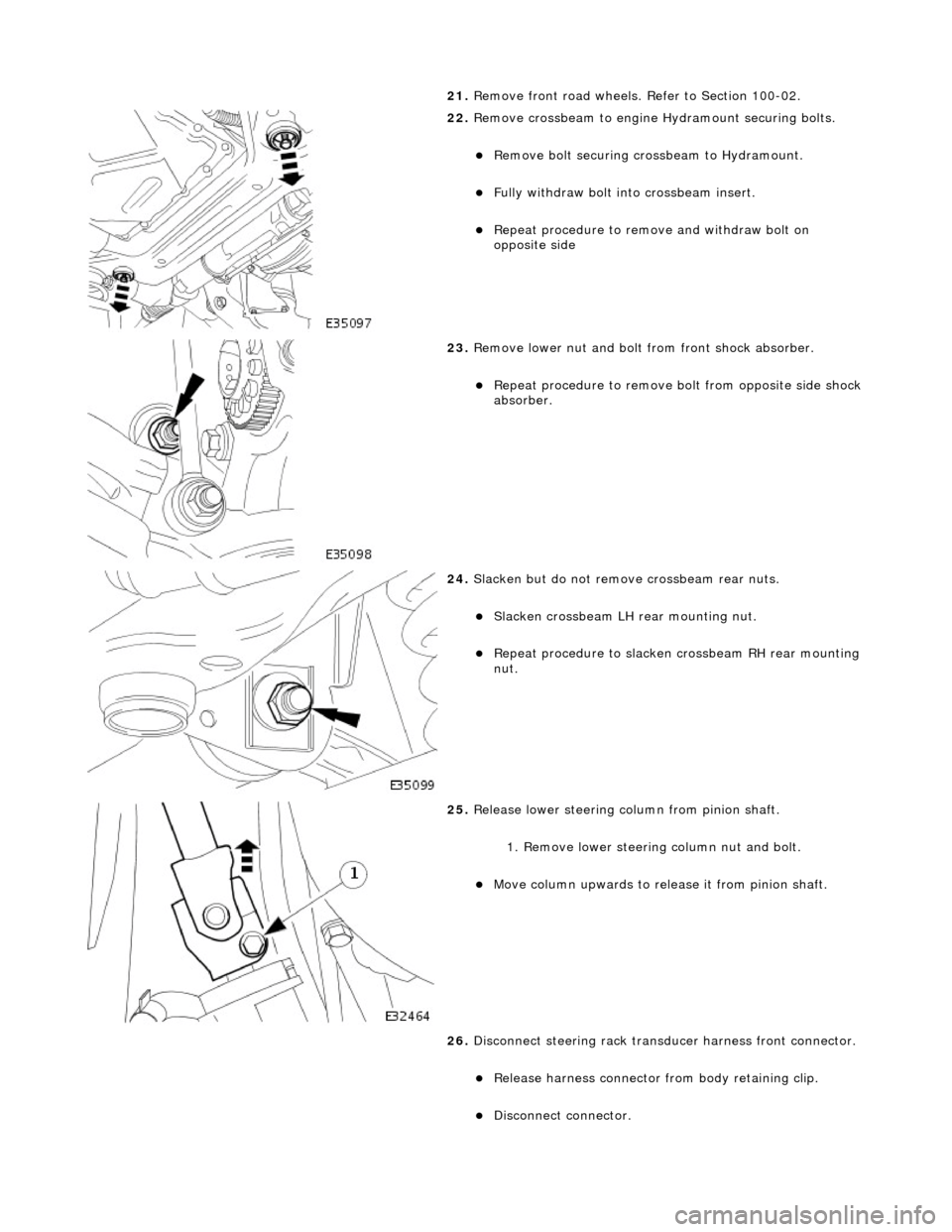
21. Remove front road wheels. Refer to Section 100-02.
22. Remove crossbeam to engine Hydramount securing bolts.
Remove bolt securing crossbeam to Hydramount.
Fully withdraw bolt into crossbeam insert.
Repeat procedure to remove and withdraw bolt on
opposite side
23. Remove lower nut and bolt from front shock absorber.
Repeat procedure to remove bo lt from opposite side shock
absorber.
24. Slacken but do not remove crossbeam rear nuts.
Slacken crossbeam LH rear mounting nut.
Repeat procedure to slacken crossbeam RH rear mounting
nut.
25. Release lower steering column from pinion shaft.
1. Remove lower steering column nut and bolt.
Move column upwards to release it from pinion shaft.
26. Disconnect steering rack transducer harness front connector.
Release harness connector from body retaining clip.
Disconnect connector.
Page 2455 of 2490

Installation
31. CAUTION: Slowly lower the crossbeam just sufficient to
provide the required clearance. Lowering the crossbeam
excessively can damage the suspension and steering pipes.
Carefully lower crossbeam to provide sufficient clearance
between front mounting and body.
32. Remove and discard heatshield from front mounting.
1. Install new heatshield over front mounting.
2. NOTE: It may be necessary to use a hammer and drift to
finally align new mounting with body location.
Carefully raise crossbeam assembly into position.
Ensure that dowels of both crossbeam mountings are
Page 2456 of 2490

correctly seated in body locations.
3. Ensure that both engine hydram ounts are correctly seated in
crossbeam locations.
4. From engine compartment, install but do not tighten
crossbeam front RH bolts.
5. From engine compartment, install crossbeam front LH bolts
and tighten to 22-28Nm.
6. Install power steering fluid reservoir.
Position reservoir on mounting bracket.
Install reservoir securi ng nuts and bolts.
Page 2458 of 2490

3. Remove special tool 303-021 from fender channel.
11. Install crossbeam to engine Hydramount bolts.
Install bolt securing Hydramou nt to crossbeam and tighten to 34-46Nm.
Repeat procedure to install crossbeam opposite side bolt.
12. Tighten rear mounting bolt and nut to 131-185 Nm.
Repeat procedure to tighten opposite side rear mounting
bolt and nut.
13. Connect steering rack transducer harness front connector.
Connect steering ha rness connector.
Install harness connector on body retaining clip.
14. Slacken adjuster nut and remove camber tie down tool 204-
114 from suspension.
Repeat procedure to remove tie down tool from opposite
side.
Page 2461 of 2490

Uni-Body, Subframe and Mounting System - Front Axle Crossmember Rear
Bushing
Removal and Installation
Removal
CAUTION: Replacement of nuts and bolts: Various thread-locking devices are used on nuts and bolts throughout the
vehicle. These devices restrict the number of times a nut or bolt can be used. See section 100-00 for information.
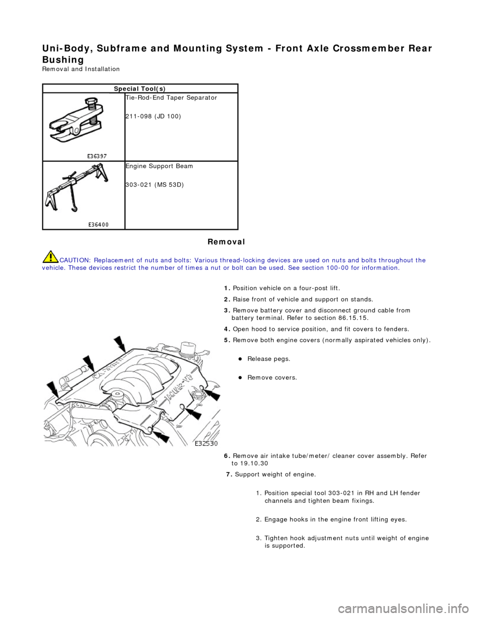
Special Tool(s)
Tie-Rod-End Taper Separator
211-098 (JD 100)
Engine Support Beam
303-021 (MS 53D)
1. Position vehicle on a four-post lift.
2. Raise front of vehicle and support on stands.
3. Remove battery cover and disc onnect ground cable from
battery terminal. Refer to section 86.15.15.
4. Open hood to service position, and fit covers to fenders.
5. Remove both engine covers (nor mally aspirated vehicles only).
Release pegs.
Remove covers.
6. Remove air intake tube/meter/ cleaner cover assembly. Refer
to 19.10.30
7. Support weight of engine.
1. Position special tool 303-021 in RH and LH fender channels and tighte n beam fixings.
2. Engage hooks in the en gine front lifting eyes.
3. Tighten hook adjustment nuts until weight of engine is supported.