Airbag module JAGUAR X308 1998 2.G Workshop Manual
[x] Cancel search | Manufacturer: JAGUAR, Model Year: 1998, Model line: X308, Model: JAGUAR X308 1998 2.GPages: 2490, PDF Size: 69.81 MB
Page 42 of 2490
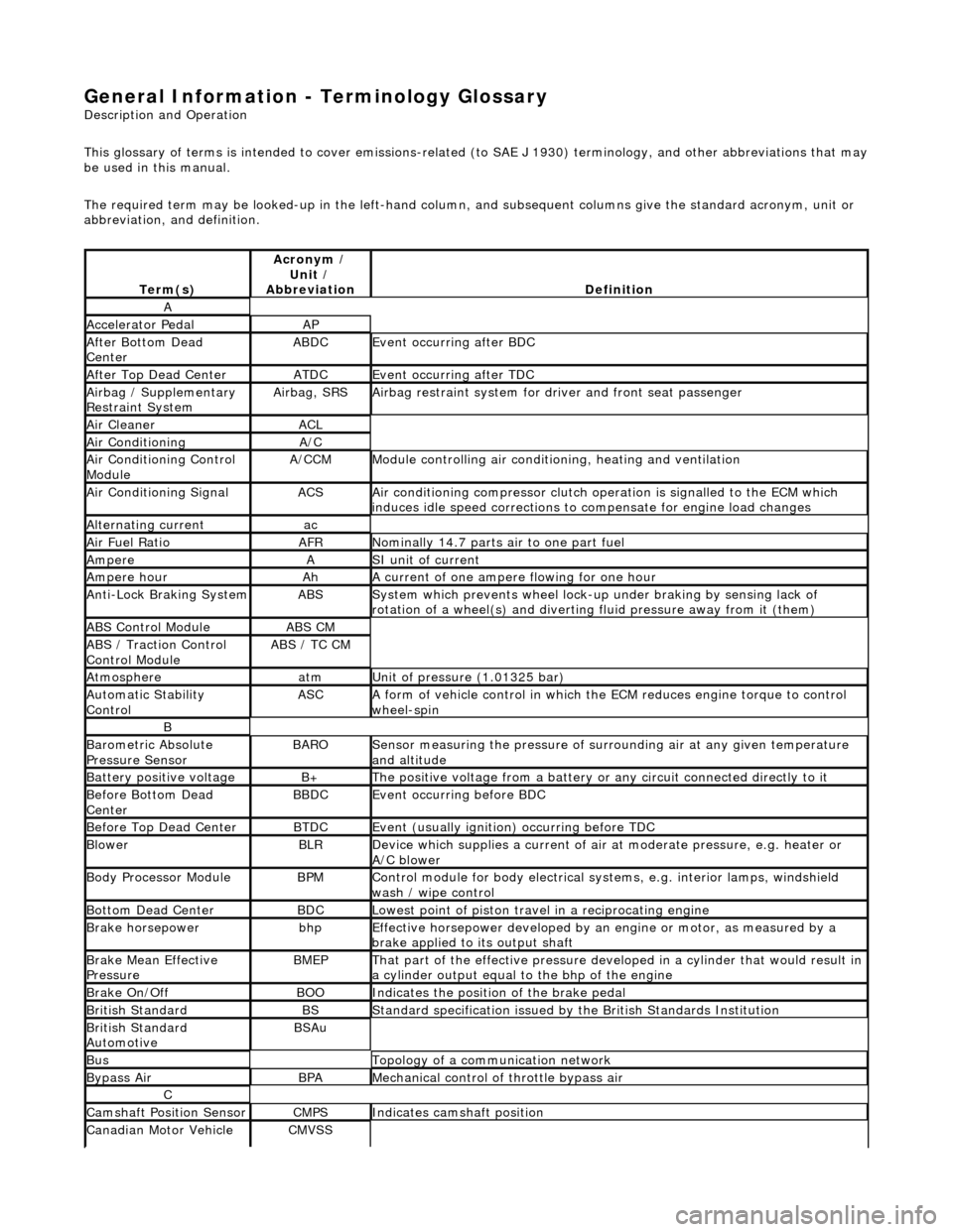
General Information - Terminology Glossary
Description an
d Operation
This glossary of terms is intended to cover emissions-related (to SAE J 1930) term inology, and other abbreviations that may
be used in this manual.
The required term may be looked-up in th e left-hand column, and subsequent columns give the standard acronym, unit or
abbreviation, and definition.
Te rm
(s)
Acr
ony
m /
Unit /
Abbreviation
De fi
nition
A
Accel
e
rator Pedal
AP
Af
ter Botto
m Dead
Center
ABDCEvent occurri ng after
BDC
Af
ter Top Dead CenterATDCEvent occurri ng after
TDC
Ai
rbag /
Supplementary
Restraint System
Airbag, SRSAi rbag restraint system for
dr
iver and front seat passenger
Air Cleane rACL
Air ConditioningA/C
Air Conditioning Con t
rol
Module
A/CCMModule c
ontrolling air conditioning, heating and ventilation
Air Conditioning SignalACSA
i
r conditioning compressor clutch operation is signalled to the ECM which
induces idle speed corrections to co mpensate for engine load changes
Alternating cu
rrent
ac
Ai
r Fuel R
atio
AFRN
omi
nally 14.7 parts air to one part fuel
Ampe
reASI unit of current
Ampere hourAhA current of one ampere
fl
owing for one hour
Anti-Lock Braking SystemABSS
y
stem which prevents wheel lock-up
under braking by sensing lack of
rotation of a wheel(s) and divertin g fluid pressure away from it (them)
ABS Control Mo
dule
ABS CM
ABS /
T
raction Control
Control Module
ABS / T
C CM
Atmosph
e
re
atmU
n
it of pressure (1.01325 bar)
Au
to
matic Stability
Control
ASCA form of vehicle
control
in which the ECM reduces en gine torque to control
wheel-spin
B
Baro me
tric Absolute
Pressure Sensor
BAR OSensor measuring the pressure of surr ou
nding air at any given temperature
and altitude
Bat t
ery positive voltage
B+The posi
ti
ve voltage from a battery or
any circuit connected directly to it
Before Bottom Dead
CenterBBDCEvent occurri ng before BD
C
Before Top Dead
Center
BTD
CEvent (usual ly
ignition) occurring before TDC
Blowe
rBLRDe
vice which supplies a current of air at
moderate pressure, e.g. heater or
A/C blower
Body Processor M
odule
BPMControl modu
le
for body electrical systems, e.g. interior lamps, windshield
wash / wipe control
Bott om D
ead Center
BD
CLowest poin t of piston
travel in a reciprocating engine
Brake hors
epowe
r
bhpEffecti
ve horsepower devel
oped by an
engine or motor, as measured by a
brake applied to its output shaft
Brake Mean Effective
Pres sureBME PThat p
art of the effective
pressure developed in a cyli nder that would result in
a cylinder output equal to the bhp of the engine
Brake On/ O
ff
BOOIn
dic
ates the position of the brake pedal
Br
it
ish Standard
BSStan
dar
d specification issued by the British Standards Institution
Br
it
ish Standard
Automotive
BSAu
BusTopology of a commu n
ication network
Bypass
AirBPAMechanica l
control of throttle bypass air
C
Camshaft Posit
i
on Sensor
CMPSIndi
cat
es camshaft position
Canadian Motor
V
ehicle
CMVSS
Page 1777 of 2490
Air Distribution and Filtering - Center Registers
Removal and Installation
Removal
Installation
1.
Remove battery cover and disconnect ground cable from battery
terminal. Refer to 86.15.19.
2. Remove passenger airbag deployment door for access. Refer to
Section 501-20.
3. Remove major gauge module veneer panel for access. Refer to
76.47.24.
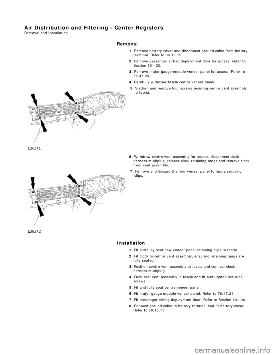
4. Carefully withdraw fascia centre veneer panel.
5. Slacken and remove four screws securing centre vent assembly
to fascia.
6. Withdraw centre vent assembly for access, disconnect clock
harness multiplug, release clock retaining tangs and remove clock
from vent assembly.
7. Remove and discard the four veneer panel to fascia securing
clips.
1. Fit and fully seat new veneer panel retaining clips to fascia.
2. Fit clock to centre vent assemb ly, ensuring retaining tangs are
fully seated.
3. Position centre vent assembly at fascia and connect clock
harness multiplug.
4. Fully seat vent assembly in fascia and fit and tighten securing
screws.
5. Fit and fully seat centre veneer panel.
6. Fit major gauge module veneer panel. Refer to 76.47.24.
7. Fit passenger airbag deployment door. Refer to Section 501-20.
8. Connect ground cable to battery terminal and fit battery cover.
Refer to 86.15.15.
Page 1848 of 2490
Control Components - Remote Climate Control ModuleRHD RWD
Removal and Installation
Removal
1. Position the driver's seat fully rearward
2. Position the steering column DOWN and fully EXTENDED
3. Disconnect the battery ground lead
4. Lower steering column cowl 76.46.03
5. Upper steering column cowl 76.46.02
6. Knee bolster, driver's side 76.46.11
7. Position the steering in the 'straight ahead'
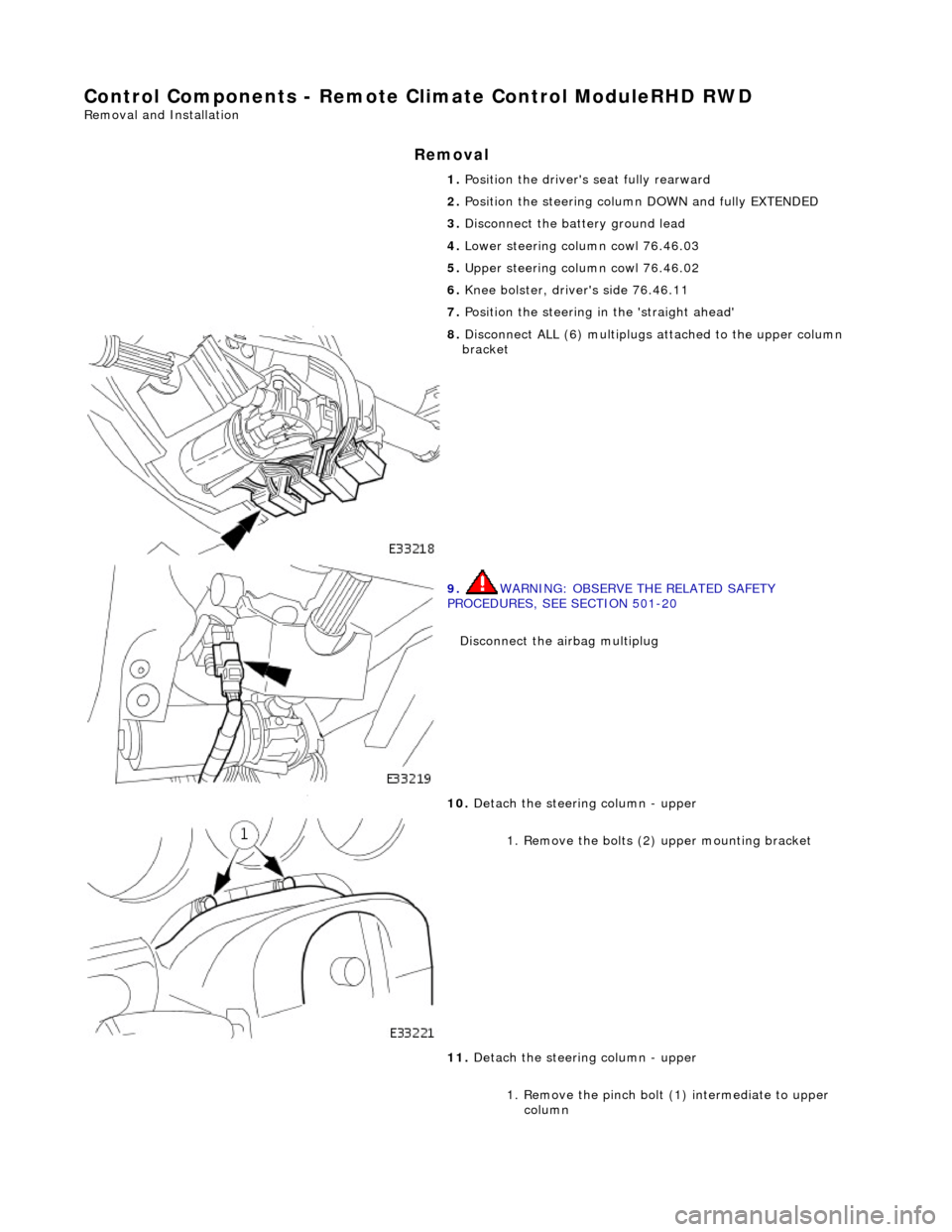
8. Disconnect ALL (6) multiplugs attached to the upper column
bracket
9. WARNING: OBSERVE THE RELATED SAFETY
PROCEDURES, SEE SECTION 501-20
Disconnect the airbag multiplug
10. Detach the steering column - upper
1. Remove the bolts (2 ) upper mounting bracket
11. Detach the steering column - upper
1. Remove the pinch bolt (1) intermediate to upper column
Page 1855 of 2490
The In
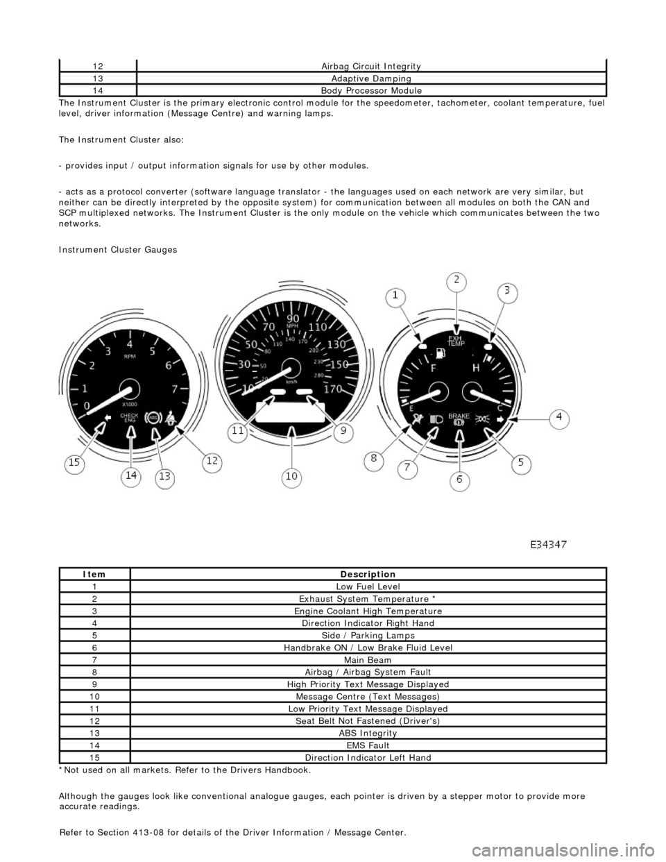
strument Cluster is the primary electronic control module for the speedomete
r, tachometer, coolant temperature, fuel
level, driver information (Message Centre) and warning lamps.
The Instrument Cluster also:
- provides input / output informatio n signals for use by other modules.
- acts as a protocol converter (software language translator - the languages used on each network are very similar, but
neither can be directly interp reted by the opposite system) for communication between all modules on both the CAN and
SCP multiplexed networks. The Instrument Cluster is the only module on the vehicle which communicates between the two
networks.
Instrument Cluster Gauges
*Not used on all markets. Refer to the Drivers Handbook.
Although the gauges look like conventional analogue gauges, each pointer is driven by a stepper motor to provide more
12Ai
rbag Circuit Integrity
13Adaptive Damping
14Body Processor
Module
It
em
De
scription
1Low Fu
el Level
2Exhaus
t System Temperature *
3E
ngine Coolant High Temperature
4Di
rection Indicator Right Hand
5Side
/ Parking Lamps
6Handbrake ON / Low
Bra
ke Fluid Level
7Main
Beam
8Ai
rbag / Airbag System Fault
9Hi
gh Priority Text
Message Displayed
10M
essage Centre (Text Messages)
11Low Pri
ority Text Message Displayed
12Se
at Belt Not Fa
stened (Driver's)
13ABS Integrity
14EMS Fault
15D
irection Indicator Left Hand
accu
rate readings.
Refer to Section 413-08 for details of the Driver Information / Message Center.
Page 1977 of 2490
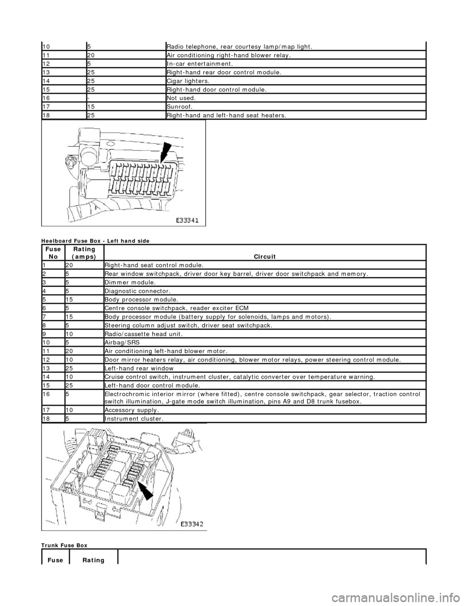
Heelboard Fuse Box - Left hand side
Trunk Fuse Box
105Radio telephone, rear courtesy lamp/map light.
1120Air conditioning right-hand blower relay.
125In-car entertainment.
1325Right-hand rear door control module.
1425Cigar lighters.
1525Right-hand door control module.
16-Not used.
1715Sunroof.
1825Right-hand and left-hand seat heaters.
Fuse NoRating
(amps)Circuit
120Right-hand seat control module.
25Rear window switchpack, driver door key ba rrel, driver door switchpack and memory.
35Dimmer module.
45Diagnostic connector.
515Body processor module.
65Centre console switchpack, reader exciter ECM
715Body processor module (battery supply for solenoids, lamps and motors).
85Steering column adjust switch, driver seat switchpack.
910Radio/cassette head unit.
105Airbag/SRS
1120Air conditioning left-hand blower motor.
1210Door mirror heaters relay, air conditioning, blow er motor relays, power steering control module.
1325Left-hand rear window
1410Cruise control switch, instrument cluster, catalytic converter over temperature warning.
1525Left-hand door control module.
165Electrochromic interior mirror (where fitted), centre console switchpack, gear selector, traction control
switch illumination, J-gate mode switch illumination, pins A9 and D8 trunk fusebox.
1710Accessory supply.
185Instrument cluster.
Fuse Rating
Page 2015 of 2490
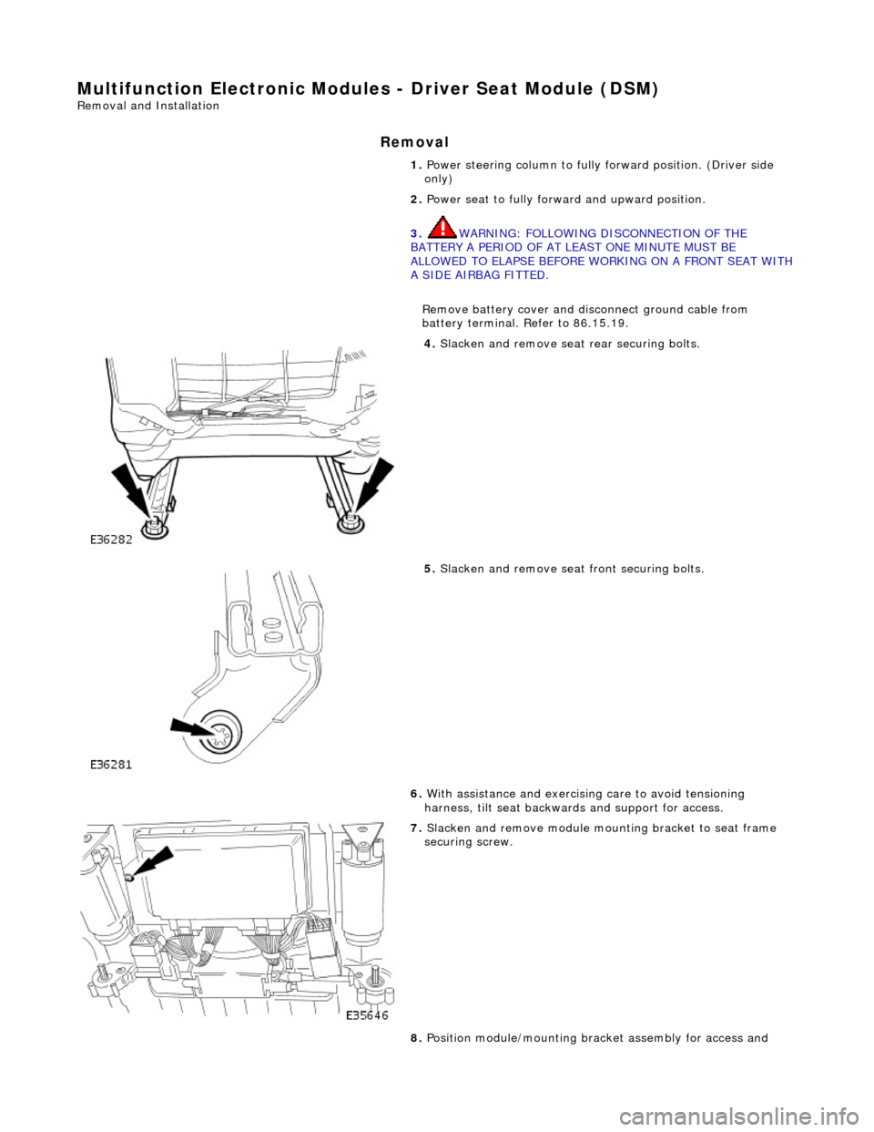
Multifunction Electronic Modules - Driver Seat Module (DSM)
Removal and Installation
Removal
1. Power steering column to fully forward position. (Driver side
only)
2. Power seat to fully forward and upward position.
3. WARNING: FOLLOWING DISCONNECTION OF THE
BATTERY A PERIOD OF AT LEAST ONE MINUTE MUST BE
ALLOWED TO ELAPSE BEFORE WORKING ON A FRONT SEAT WITH
A SIDE AIRBAG FITTED.
Remove battery cover and disc onnect ground cable from
battery terminal. Refer to 86.15.19.
4. Slacken and remove seat rear securing bolts.
5. Slacken and remove seat front securing bolts.
6. With assistance and exercising care to avoid tensioning
harness, tilt seat backwa rds and support for access.
7. Slacken and remove module moun ting bracket to seat frame
securing screw.
8. Position module/mounting bracket assembly for access and
Page 2024 of 2490
located behind the trunk lid badge.
Occupant Restraints
Inertia reel seat belts with electronically controlled pre-tensioners are installed at the front seats. Supplementary occupant
restraint is provided for driver and front seat passenger by front airbags, and side air bags installed in the outer wing of
each front seat. Standard inertia reel type belts are fitted to all three rear seat positions. The front seat belts are provide d
with height adjuster units which are attached one to each of the 'B' posts. Where emergency locking retractor/automatic
locking retractor seat belts are provided, the belts have two operating modes.The inertia reel mode with emergency locking
retractor is for adult passenge r use only and operates to allow the occupant some freedom of tors o movement under normal
travel conditions.. The static reel mode which prevents belt payout and must be used when a ch ild seat is installed, is
activated by fully extending the belt to engage the ratchet me chanism,.then releasing the belt. Operation of the ratchet will
then be felt and the belt w ill become locked in that position. To revert to in ertia reel (adult passenger) mode, pay the belt
back into the reel to th e fully retracted position.
Body Structure
The XJ8 sedan body is produced in monocoque standard and lo ng wheelbase form. 70% of the body panels are zinc coated
to achieve optimum corrosion protection and a further 8% are constructed in high st rength steels to provide high torsional
strength and passenger impact protection.
Doors
Each front and rear door consists of a we lded, mild steel inner frame and an outer panel. The outer panel is welded to the
waist rail and cheater of the inner frame, then bonded and clinched to fo rm the door assembly. Cosmetic PVC bead is
applied to all clinch joints
Hood
The hood consists of one piece inner an d outer panels clinched and bonded toge ther, with cosmetic bead PVC sealant
applied to all clinch joints. The hood pivo ts at the front on two hinges each secured by bolts to the hood front underside and
the BIW front upper crossmember. Two gas struts secured to the hood by pi vot pins and snap-on couplings, support the
hood in the open position.
Trunk
The trunk lid is of similar construction to the hood, consisting of inner and outer panels clinched and bonded together and
PVC bead sealed. The trunk accommodates the spare wheel, the battery, an electrical carrier containing electrical fuses,
relays and modules and where premium ICE is fitted, a compac t disc auto-changer mounted on body bracketry. Carpet
covered trims line the trunk sides and front inner panel and a po lyurethane rear finisher is secured to the rear panel by
spring clips and fir tree fasteners.
B and C Post Reinforcement
Page 2122 of 2490

Seating - Front Seat
Removal and Installation
Removal
1. Move the seat fully rearward and slacken and remove the
front securing bolts.
2. Move steering wheel to fully forward position.
3. Ensure that squab is fully upright, then move the seat fully
forward.
4. WARNING: FOLLOWING DISCONNECTION OF THE
BATTERY A PERIOD OF AT LEAST ONE MINUTE MUST BE
ALLOWED TO ELAPSE BEFORE WORKING ON A FRONT SEAT WITH
A SIDE AIRBAG FITTED.
Remove battery cover and disc onnect ground cable from
battery terminal. Refer to 86.15.19.
5. Remove the slider covers an d slacken and remove the two
rear securing bolts.
6. Supporting and positioning the seat for access, disconnect
multiplugs.
Disconnect side air bag harness multiplug.
Release from retaining brackets and disconnect seat
harness multiplugs.
Disconnect seat control module harness multiplug.
Cut through and remove any ti es securing harnesses to
seat frame.
7. NOTE: Securing bolt remains captive with belt anchor.
Slacken and remove seat be lt anchor securing bolt.
Page 2149 of 2490
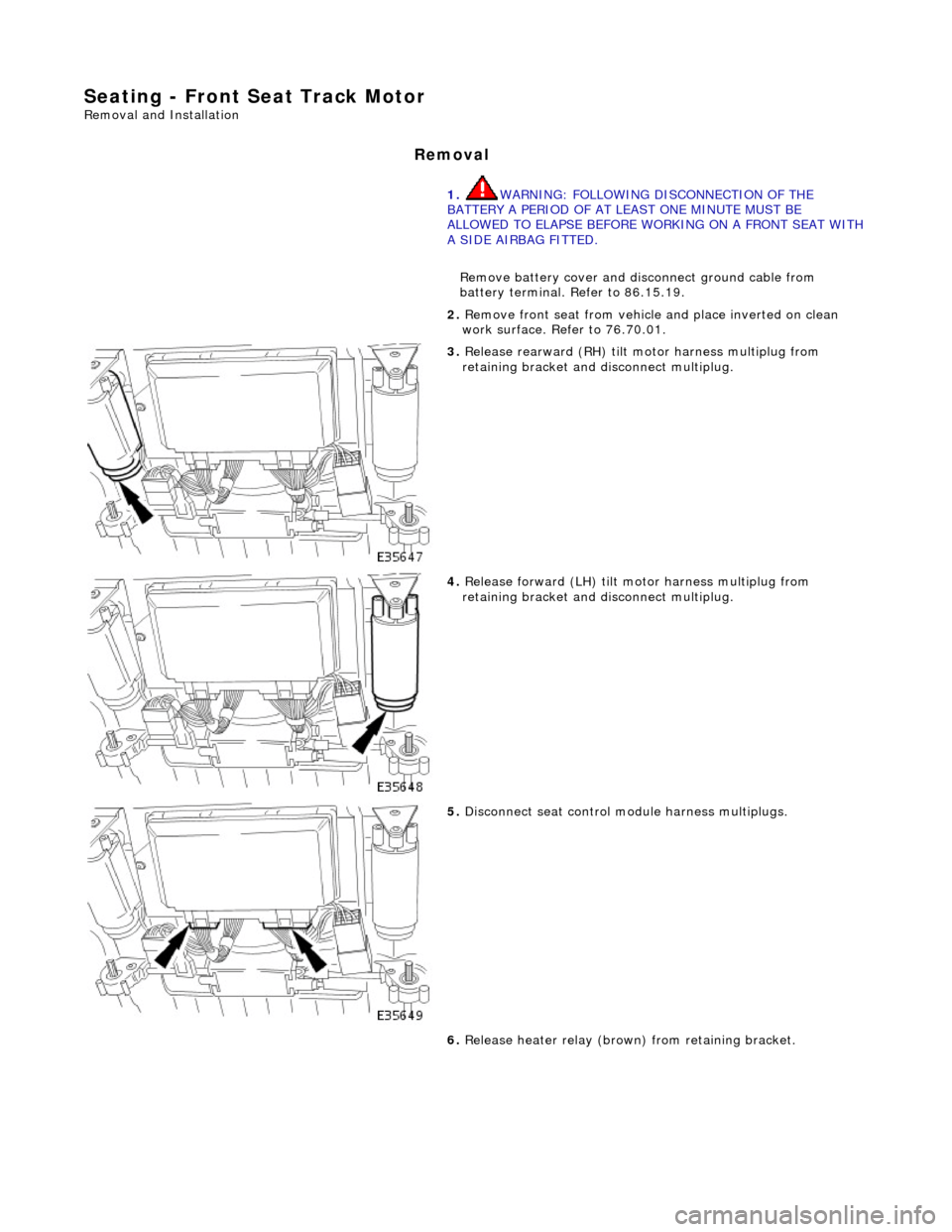
Seating - Front Seat Track Motor
Removal and Installation
Removal
1. WARNING: FOLLOWING DISCONNECTION OF THE
BATTERY A PERIOD OF AT LEAST ONE MINUTE MUST BE
ALLOWED TO ELAPSE BEFORE WORKING ON A FRONT SEAT WITH
A SIDE AIRBAG FITTED.
Remove battery cover and disc onnect ground cable from
battery terminal. Refer to 86.15.19.
2. Remove front seat from vehicle and place inverted on clean
work surface. Re fer to 76.70.01.
3. Release rearward (RH) tilt motor harness multiplug from
retaining bracket and di sconnect multiplug.
4. Release forward (LH) tilt motor harness multiplug from
retaining bracket and di sconnect multiplug.
5. Disconnect seat control module harness multiplugs.
6. Release heater relay (brown ) from retaining bracket.
Page 2242 of 2490

Instrument Panel and Console - Instrument Panel
Removal and Installation
Removal
1. Turn ignition switch to position II.
2. Motor driver and front passenger seats rearward.
3. Position steering wheel in stra ight ahead position and fully
lower and extend steering column.
4. Turn ignition switch to position O.
5. Remove battery cover and disc onnect ground cable from
battery terminal. Refer to 86.15.19.
6. Remove 'J' gate finish er. Refer to 76.25.24.
7. Remove 'J' gate finisher retain ing panel. Refer to 76.25.26.
8. Remove centre console veneer panel. Refer to 76.47.26.
9. Disconnect and remove radio.
10. Remove centre console switch module. Refer to 86.80.32.
11. Remove centre console. Refer to 76.25.01.
12. Slacken and remove centre cons ole vent duct rear securing
screw and withdraw duct assemb ly from air conditioning unit
manifold.
13. WARNING: BEFORE ANY AIRBAG/SRS SERVICE IS
PERFORMED, AT LEAST ONE MINUTE MUST ELAPSE AFTER
DISCONNECTION OF THE BATTERY CABLE, TO ALLOW
DISSIPATION OF BACK-UP POWER SUPPLY ENERGY.
Remove driver airbag. Refer to 76.73.39.
14. Remove steering wheel. Refer to Section 211-04.
15. Remove steering column lo wer cowl. Refer to 76.46.03.
16. Remove steering column u pper cowl. Refer to 76.46.02.
17. Remove driver side unders cuttle. Refer to 76.46.11.
18. Remove combined windshield wiper/washer switch and
audible warning speaker assembly. Refer to 86.65.42.
19. Remove glovebox. Refer to 76.52.03.
20. Remove 'A' post lower trim pads. refer to 76.13.30.
21. Carefully withdraw driver stowage bin trim, remove bin
securing screw and remove bin from facia.