change time JAGUAR X308 1998 2.G Workshop Manual
[x] Cancel search | Manufacturer: JAGUAR, Model Year: 1998, Model line: X308, Model: JAGUAR X308 1998 2.GPages: 2490, PDF Size: 69.81 MB
Page 37 of 2490
patc
hed fastener of the same specification fitted. All mating th
reads must be thoroughly cleaned prior to fitting of the new
fastener.
Jaguar Specification JFS 02.01.04 patched fasteners incorporat e a plastic/polyester on the thread. Acting as a wedge
between the mating threads, this compound imposes a prevaili ng torque during tightening. Whilst this type of patched
fastener can be re-used, the imposed torq ue diminishes. It is therefore recommended that following third removal, this type
of patched fastener is discarded and a new fast ener of the same specification is fitted.
Special fasteners bearing the following pa rt numbers are of the micro-encapsulated adhesive type and following removal,
must be discarded and replaced by ne w items of the same specification:
CAC 8223
JZB 10060; JZB 10061; JZB 10078.
JZH 100027.
JZS 100082; JZS100087; JZS 100088; JZS 100089; JZS 100090; JZS 100118; JZS 100157; JZS 100164; JZS 100166.
NCA 1451 AA.
Vehicle Specifications
Purchasers are advised th
at th
e specification details set out in this manual apply to a range of vehicles and not to any
specific one. For the specificatio n of a particular vehicle, purchasers should consult their dealer.
The Manufacturer reserves the right to vary the specifications, with or without notice, and at such times and in such manner
as the Manufacturer thinks fit. Major as well as minor changes may be involved , in accordance with the Manufacturer's
policy of continuous improvement.
Whilst every effort is made to ensure the accuracy of the pa rticulars contained in this manual, neither the Manufacturer nor
the Dealer, by whom the manual is supplied, shall in any circumstances be held liable for any inaccuracy or the
consequences thereof.
Serv
ice Repair Operation Numbering
A
master index of numbered operations has been compiled for
universal application to all vehicles manufactured by Jaguar
Cars Ltd.
Each operation is allocated a number from the master index and cross-refers with an identical number in the Repair
Operation Times schedule. The number consists of six digits arranged in three pairs.
Each maintenance procedure in this manual is described in the sequence necessary to complete the operation in the
minimum time, as specified in the Repair Operation Times schedule for this range of vehicles.
Re
ferences to Left- and Right-Hand
R
eferences to the left- or
right-hand side of the vehicle are made as if viewing from the driver's seat.
Ref
erences to Engine Banks
Wi
th the engine installed in the vehicle, the right-hand cylinder
bank is designated Bank A, and the left-hand cylinder bank
is designated Bank B.
Specia
l Tools
Any special too
ls and equipment required
to perform a maintenance procedure, are shown at the beginning of each
maintenance procedure.
Page 47 of 2490
Mem
ory
Pulse Width ModulationPW
M
A
method of control in an electronic co
ntrol system in which the duration of
pulses in a pulse train is proportional to the amplitude of the modulating
signal
R
Ran
dom Access Memory
RAMF
ast access memory store which is accessible for entry or extraction of data
Re
ad-Only Memory
RO
M
F
ast access memory in which data
is fixed and may not be changed
Re
servoir
RESContaine
r, usually for oils,
coolants or hydraulic fluids
Re
turn
RTNA
dedicated sensor ground circuit
R
evolutions Per Minute
RP
M
Shaft speed o
f a device, us
ually an engine or motor
R
ight-hand
RH
Right-hand drive veh
icle
RHD
S
Scan T
ool
STDe
vice that interfaces with and comm
unicates information on a data link
Se
at Control Module
SCMModule
controlling the seat motor systems (not electric raise/lower-only
seats)
Secon
dary Air
Air pro
vided to the exhaust system
Secon
dary Air Injection
AIRSy
stem used for a period of time each
time the engine is started, unless
certain temperature criter ia are met. Pumps air directly into the exhaust
system which generates extra heat and reduces the time taken for the
catalytic converters to reach operating temperature
Secon
dary Air Injection
Bypass
AIRBVents secon
dary air to atmosphere
Secon
dary Air Injection
Check Valve
AIRCValve wh
ich prevents back-flow of exhaust gas to the AIR system when the
system is inoperative
Secon
dary Air Injection
Diverter
AIRDD
iverts secondary air to either
the catalyst or exhaust manifold
Secon
dary Air Injection
Magnetic Clutch
AIRP
C
Clu
tch mounted on the AIRP drive shaft
Secon
dary Air Injection
Pump
AIRPMe
chanically driven rotary vane
pump, driven through the AIRPC
Secon
dary Air Injection
Relay
AIRRCont
rols the injection of air into the exhaust system
Secon
dary Air Injection
Switchin
g Va
lve
AIRSV
acuum operated valve backing-up the AIRC
Secu
rity and Locking
Control Module
SLCMModul
e controlling the vehicle's security and closure-locking functions
SensorSGeneri
c name for a device
that senses either the absolute value or a change
in a physical quantity su ch as temperature, pressure or flow rate, and
converts that change into an electrical quantity signal
Servic
e Repair Operation
(number)
SRONu
mber generated by Jaguar Methods
and Techniques system which relates
to the time allowed to complete a repair operation. Further information on the
system can be found in the separate Jaguar Publications (for each model
range) entitled 'Repair Operation Times'
Shif
t signal
SDA
shift process signal to the TCM on SC vehicles
Shif
t Solenoid
SSControls shi
fting in an automatic transmission
Si
gnal return
SIG RTN
Slidin
g Roof Control
Module
SRCM
Society of Automotive
Engineers
SAE
Speed
Control Control
Module
SCCMModule con
trolling Speed Control System
Square c
entimeter
cm
2
Stan
dard
std
Stan
dard Corporate
Protocol
SCPA
high-speed, serial communications system linking all body system control
modules. Control messages and data ar e passed between modules at up to
786 messages per second
SuperchargerSCAn in
take system which utilizes a supercharger (mechanically driven device
that pressurizes intake air, thereby in creasing density of charge air and the
consequent power output from a given displacement)
Supercharger
Bypass
SCB
SwitchSW
T
Page 318 of 2490
Comp
onent Tests
Bra
k
e Booster
1.
1. Chec k all
hoses and connections. All unused vacuum connectors should be capped. Hoses and their connections
should be correctly secured and in good condition with no holes and no collapsed areas. Inspect the valve on the
brake booster for damage.
2. 2. Check the hydraulic brake system for leaks or low fluid.
3. 3. With the transmission in PARK, stop the engine and apply the parking brake. Pump the brake pedal several times
to exhaust all vacuum in the system.
4. 4. With the engine switched off and all vacuum in the system exhausted, appl y the brake pedal and hold it down.
Start the engine. If the vacuum system is operating, the brake pedal will tend to move downward under constant
foot pressure. If no motion is felt, the vacuum booster system is not functioning.
5. 5. Remove the vacuum hose from the brake booster. Manifold vacuum should be available at the brake booster end
of the hose with the engine at idle speed and the transm ission in PARK or NEUTRAL. Make sure that all unused
vacuum outlets are correctly capped, hose connectors are correctly secured and vacuum hoses are in good
condition. When it is established that manifold vacuum is available to the brake booster, connect the vacuum hose
to the brake booster and repeat Step 3. If no downward movement of the brake pedal is felt, install a new brake
booster.
6. 6. Operate the engine for a minimum of 10 seconds at a fast idle. Stop the engine and allow the vehicle to stand for
10 minutes. Then, apply th e brake pedal with approximately 89 N ( 20lb) of force. The pedal feel (brake
application) should be the same as that noted with the engine running. If the brake pedal feels hard (no power
assist), install a new valve and then re peat the test. If the brake pedal still feels hard, in stall a new brake booster.
If the brake pedal movement feels spongy, bleed the brak e system. For additional information, refer to General
Procedures in this section.
Bra k
e Master Cylinder
Usual
l
y, the first and strongest
indicator of anything wrong in the brake syst em is a feeling through the brake pedal. In
diagnosing the condition of the brake master cylinder, check pedal feel as evidence of a brake concern. Check for brake
warning lamp illumination and the brake fluid le vel in the brake master cylinder reservoir.
Normal Conditio
ns
The fo
llowing conditions are considered norm
al and are not indications that the brake master cylinder is in need of repair.
New bra
ke systems are designed to produc
e a pedal effort that is not as hard as in the past. Complaints of light
pedal efforts should be compared to the pedal effort s of another vehicle of the same model and year.
The fl
uid level will fall with brake pad wear.
Abnormal Conditions
•
NOTE: Prior to carrying out any diag
nosis, make sure the brake system warning indicator is functional.
Changes in the brake pedal feel or brake pedal travel are in dicators that something could be wrong in the brake system. The
diagnostic procedure and techniques use brake pedal feel, warning indicator illu mination and low brake fluid level as
indicators to diagnosing brake system co ncerns. The following conditions are cons idered abnormal and indicate that the
brake master cylinder is in need of repair:
Brake ped a
l goes down fast. Th
is could be caused by an ex ternal or internal leak.
Brake pedal goes down slowly
. This could be
caused by an internal or external leak.
Brak
e pedal is low or feels spongy. This condition may be ca
used by no fluid in the brake master cylinder, reservoir
Page 471 of 2490
Stee
ring System - General Informatio
n - Power Steering System Filling
and Bleeding
Gen
eral Procedures
Fluid Level Indica
tor
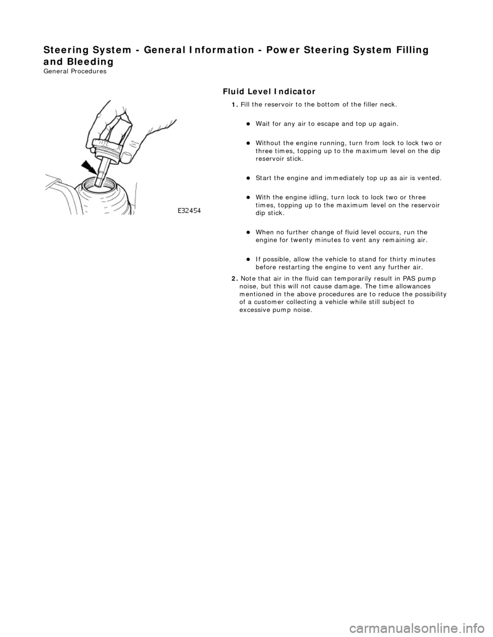
1.
F
ill the reservoir to the bo
ttom of the filler neck.
W
ait for any air to escape and top up again.
W
ithout the engine running, tu
rn from lock to lock two or
three times, topping up to the maximum level on the dip
reservoir stick.
St
art the engine and
immediately top up as air is vented.
W
ith the engine idling, turn
lock to lock two or three
times, topping up to the ma ximum level on the reservoir
dip stick.
W
hen no further change of
fluid level occurs, run the
engine for twenty minutes to vent any remaining air.
If po
ssible, allow the vehicle
to stand for thirty minutes
before restarting the engine to vent any further air.
2. Note that air in the fluid can temporarily result in PAS pump
noise, but this will not cause damage. The time allowances
mentioned in the above procedures are to reduce the possibility
of a customer collecting a vehicle while still subject to
excessive pump noise.
Page 931 of 2490
s
ystem (pressure).
Outputs from the ECM control the radiator fans control module, located behind the left hand side of the bumper, to operate
the fans in the series mode (slow), paralle l mode (Fast) or Off modes. Hysteresis in the temperature and pressure switching
values prevents 'hun ting' between modes.
Under hot operating conditions, the fans may continue to operat e for some time after the engine has been switched off, but
will stop automatically when the coolant te mperature has been sufficiently reduced.
Engine Coolant Temperature Sensor (ECT) and ECM
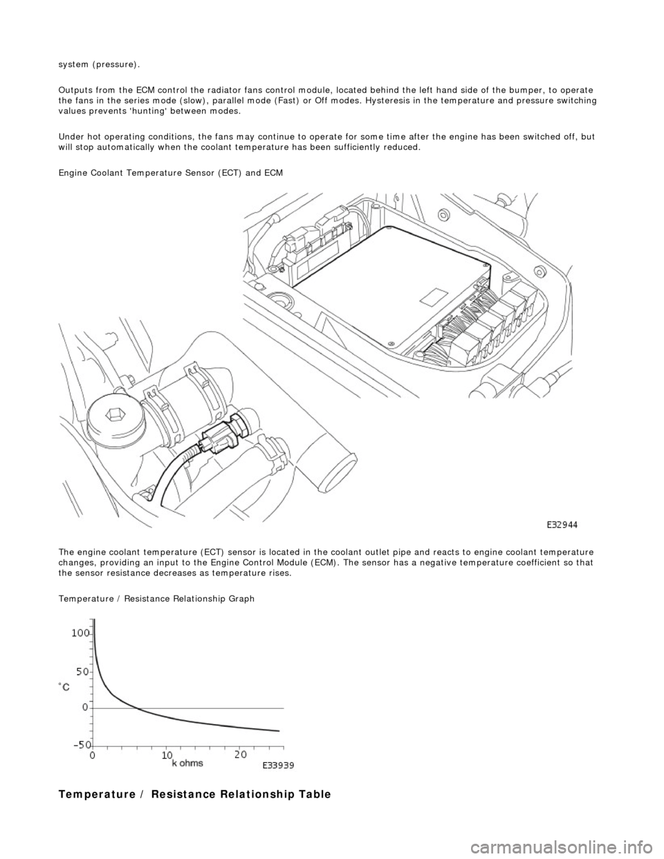
The engine coolant temperature (ECT) sensor is located in the coolant outlet pipe and reacts to engine coolant temperature
changes, providing an input to the Engine Control Module (ECM). The sensor has a negative te mperature coefficient so that
the sensor resistance decrea ses as temperature rises.
Temperature / Resistance Relationship Graph
T
emperature / Resistance
Relationship Table
Page 1149 of 2490
The E
VAP canister purge valve controls th
e flow rate of fuel vapour drawn into the engine during the canister purge
operation. The valve is opened by a vacu um feed from the induction elbow : the vacu um feed is controlled by the integral
valve solenoid and is applied when the so lenoid is energised. The solenoid is pulsed on (energised) and off by a fixed
frequency (100Hz) variable pulse width control signal (pulse width modulation). By varying the pulse on to off time, the
ECM controls the duty cycle of the valve (time that the valve is open to time closed) and thus the vapour flow rate to the
engine.
With no ECM signal applied to the va lve solenoid, the valve remains closed.
Can
ister Purge Operation
The
following pre-conditions are ne
cessary for purging to commence :
aft
er battery disconnection/reconnection, engine
management adaptations must be re-instated.
engine has run for
at least 8 seconds.
engi
ne coolant temperature is not less than 70 °C.
engine
not running in the fuel
cut off condition (eg overrun).
t
he adaptive fuel correction
function has not registered a rich or lean failure
t
he evaporative emission leak test has not failed
no faults have been diagnosted in th
e rel
evant sensor and valve circuits -
Air Flow Meter (AFM), Engine Coolant
Temperature sensor, Evaporativ e Canister Purge valve and Canister Close Valve (CCV).
If these conditions have been satisfied, purging is started. If any failures are registered, purging is inhibited.
The canister(s) is purged during each driv e cycle at various rates in accordance with the prevailing engine conditions. The
engine management software st ores a map of engine speed (RPM) against engine load (grams of air inducted / rev). For
any given engine speed and load, a vapour purge rate is assigned (purge rate increases with engine speed and load).
The preset purge rates are base d on the assumption of a vapour concentratio n of 100%. The actual amount of vapour is
measured by the closed loop fueling system : the input of evaporative fuel into the engine causes the outputs from the
upstream oxygen sensors to change, the am ount of change providing a measure of the vapour concentration. This feedback
causes the original purge rate to be adju sted and also reduces the amount of fuel input via the injectors to maintain the
correct air to fuel ratio.
Engine speed/load mapping and the corresp onding purge rates are different for single canister, running loss and ORVR
evaporative systems.
Page 1179 of 2490
generates a signal when th
e dr
ive plate passes the sensor
sen
ds the ECM signals indicating crankshaft position and engine speed
is e
ssential for calculating spark timing
En
gine Coolant Temperature (ECT) Sensor
sen
ds the ECM a signal indicating the temperature of the engine coolant
is a t
emperature dependent resistor with a negative temperature coefficient (resistance changes inversely with
respect to temperature) and is constantly monitored by the ECM
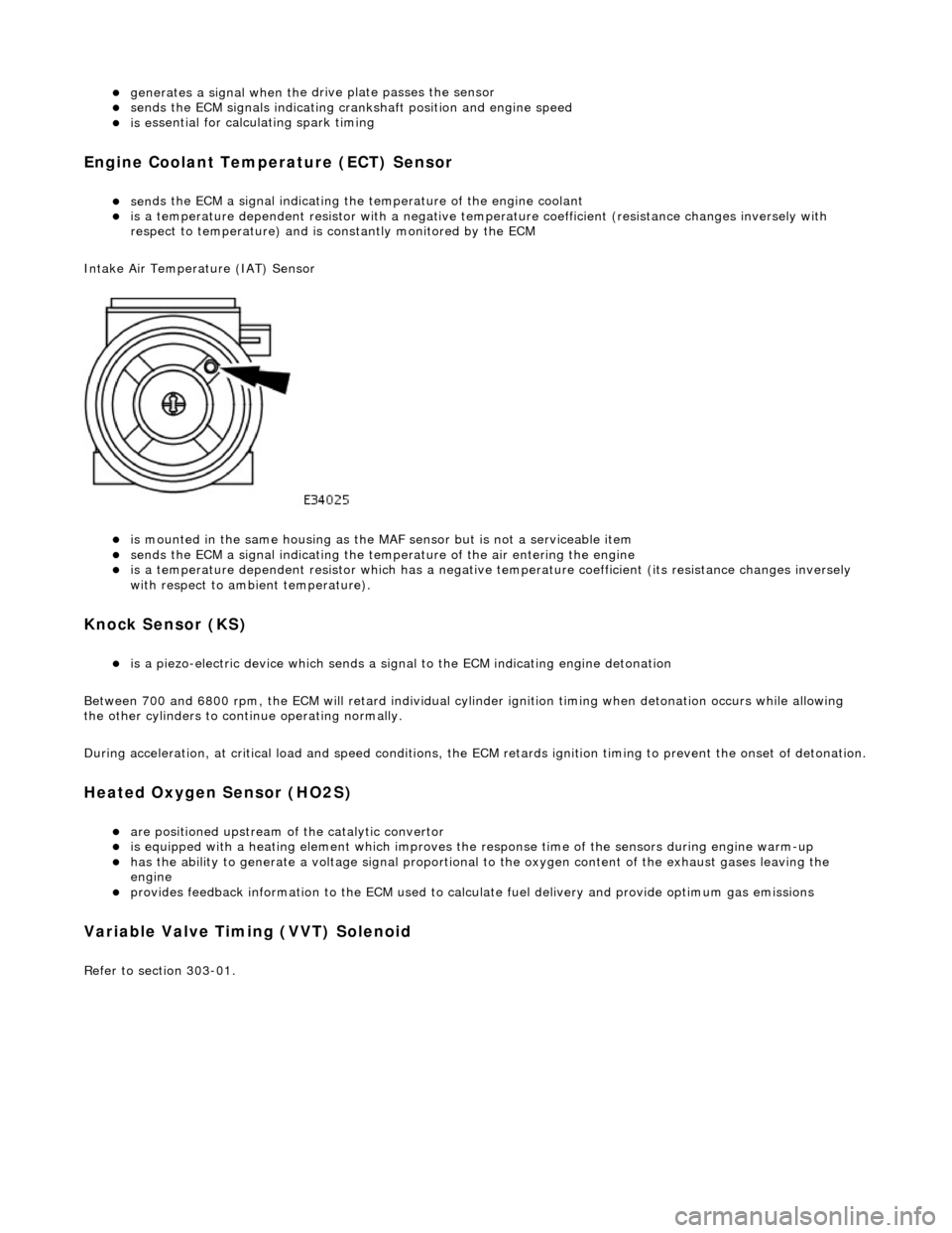
Intake Air Temperature (IAT) Sensor
is m
ounted in the same housing as the MA
F sensor but is not a serviceable item
sen
ds the ECM a signal indicating the temperature of the air entering the engine
is a t
emperature dependent resistor which has a negative
temperature coefficient (its resistance changes inversely
with respect to ambient temperature).
Knock S
ensor (KS)
is a pi
ezo-electric device which sends a signal
to the ECM indicating engine detonation
Between 700 and 6800 rpm, the ECM will retard individual cylinder ignition timing when detonation occurs while allowing
the other cylinders to continue operating normally.
During acceleration, at critical load and speed conditions, the ECM retards ignition timing to prevent the onset of detonation.
H
eated Oxygen Sensor (HO2S)
are
positioned upstream of the catalytic convertor
is equipped with
a heating element wh
ich improves the response time of the sensors during engine warm-up
h
as the ability to generate a voltage signal proportional to the oxygen content of the exhaust gases leaving the
engine
pr
ovides feedback information to the ECM used to calc
ulate fuel delivery and provide optimum gas emissions
Variable V
alve Timing (VVT) Solenoid
R
efer to section 303-01.
Page 1271 of 2490
Controller Area Network (CAN)
The TCM is an integral part of the CAN system which facilitates the interchange of real-time data between control modules
and sensors. Please see section 303- 14 for a full description of CAN.
OBDII Interface
Data concerning OBDII related transmission failures is stored in the ECM for access via the J1962 socket.
System Functions
Range Selection
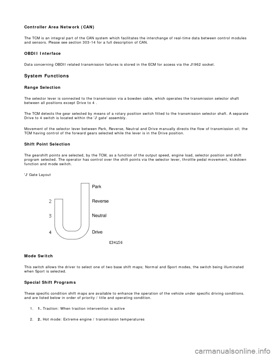
The selector lever is connected to the transmission via a bowden cable, which operates the transmission selector shaft
between all positions except Drive to 4 .
The TCM detects the gear selected by means of a rotary position switch fitted to the transmission selector shaft. A separate
Drive to 4 switch is located within the 'J' gate' assembly.
Movement of the selector lever between Park, Reverse, Neutral and Drive manually directs th e flow of transmission oil; the
TCM having control of the forward gears selected while the lever is in the Drive position.
Shift Point Selection
The gearshift points are selected, by the TCM, as a function of the output speed, engine load, selector position and shift
program selected. The operator has control over the shift points via the selector lever, throttle pedal movement, kickdown
function and mode switch.
'J' Gate Layout
Mode Switch
This switch allows the driver to select one of two base shift maps; Normal and Sport modes, the switch being illuminated
when Sport is selected.
Special Shift Programs
These specific condition shift maps are available to enhance the operation of the vehicle under specific driving conditions.
and are listed below in order of priority / title and operating condition.
1. 1. Traction: When traction intervention is active
2. 2. Hot mode: Extreme engine / transmission temperatures
Page 1395 of 2490
and/or increased performance as appropriate.
Serial Communications Interfaces
Controller Area Network (CAN)
The TCM is an integral part of the CAN system which facilita tes the interchange of real-time data between control modules
and sensors; refer to 303-14 fo r a full description of CAN.
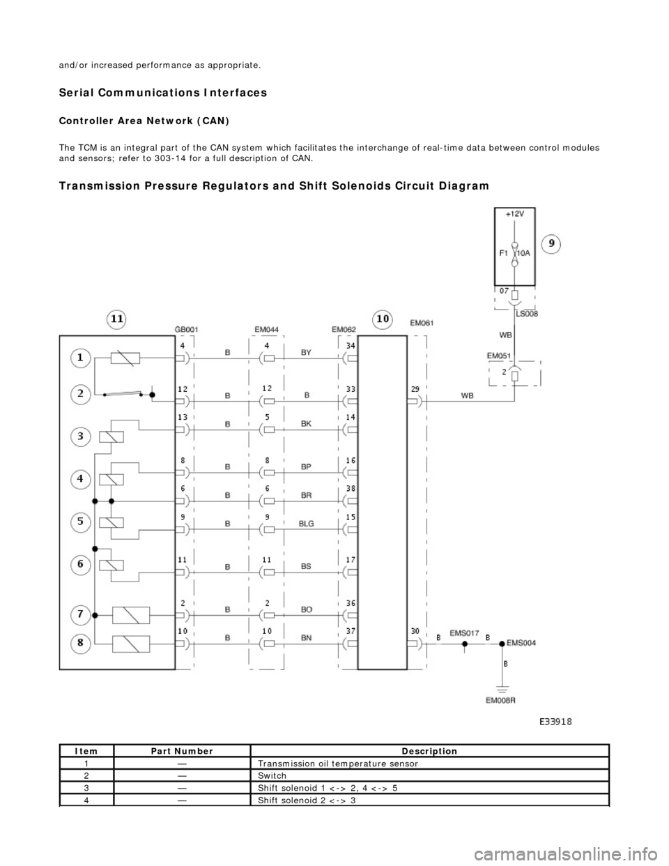
Transmission Pressure Regulators and Shift Solenoids Circuit Diagram
ItemPart NumberDescription
1—Transmission oil temperature sensor
2—Switch
3—Shift solenoid 1 <-> 2, 4 <-> 5
4—Shift solenoid 2 <-> 3