bulb JAGUAR X308 1998 2.G Workshop Manual
[x] Cancel search | Manufacturer: JAGUAR, Model Year: 1998, Model line: X308, Model: JAGUAR X308 1998 2.GPages: 2490, PDF Size: 69.81 MB
Page 25 of 2490

Rear Door Speaker (86.50.14)
Rear Door Tweeter Speaker (86.50.62)
Subwoofer
Speaker (86.51.05)
417: Lighting
417‐01: Exterior Lighting
Specification
Description and Operation
Exterior Lighting
Diagnosis and Testing
Exterior Lighting
Removal and Installation
Brake Pedal Position (BPP) Switch
Fog Lamp Switch (86.65.10)
Front Fog Lamp (86.
40.96)
Front Fog Lamp Bulb (86.40.94)
Front Side Marker Lamp (86.40.59)
Front Side Marker Lamp Bulb (86.40.58)
Front Turn Signal Lamp Bulb (86.40.41)
Headlamp Assembly (86.41.33)
Headlamp Leveling Motor (86.42.04)
High Beam Headlamp (86.41.34)
High Beam Headlamp Bulb (86.40.12)
High Mounted Stoplamp (86.41.01) (86.41.32)
High Mo
unted Stoplamp Bulb (86.41.02)
License Plate Lamp (86.40.86)
License Plate Lamp Bulb (86.40.85)
Low Beam Headlamp (86.41.35) ‐ Vehicles Without: Headlamp Leveling
Low Beam Headlamp (86.41.35) ‐ Vehicles With: Headlamp Leveling
Low Beam Headlamp Bulb (86.40.08)
Rear Lamp Assembly (86.40.70)
Rear Lamp Assembly Bulb (86.40.73)
Rear Side Marker La
mp (86.41.08)
Rear Side Marker Lamp Bulb (86.41.07)
Side Lamp Bulb (86.40.27)
Side Lamp/Front Turn Signal Lamp (86.40.39)
Page 26 of 2490

Side Turn Signal Lamp (86.41.41)
Side Turn Signal Lamp Bulb (86. 41.42)
417‐02
:
Interior Lighting
Specification
Description and Operation
Interior Lighting
Diagnosis and Testing
Interior Lighting
Removal and Installation
Door Courtesy Lamp (86.40.38)
Door Courtesy Lamp Bulb (86.40.47)
Door Courtesy Lamp Lens (86.40.35)
Glove Co
mpartment Lamp (86.45.08)
Luggage Compartment Lamp (86.45.16)
Vanity Mirror Lamp (76.10.50)
417‐04: Daytime Running Lamps (DRL)
Description and Operation
Daytime Running Lamps (DRL)
Diagnosis and Testing
Daytime Running Lamps (DRL)
418: Electrical Distribution
418‐00: Module Communications Network
Description and Operation
Communications Ne
twork
Removal
and Installation
Battery
Junction Box (BJB) (86.70.69)
Central
Junction Box (CJB) (86.70.72)
Front
Auxiliary Junction Box (86.70.73)
Rear
Auxiliary Junction Box (86.70.74)
418 ‐02: Wiring Harnesses
Description and Operati
on
Wiring Harness
General Procedures
Wiring Harness Repair
Page 30 of 2490

501‐10: Seating
Specificatio
n
Description and Operation
Seats
Removal and Installation
Front Seat (76.70.01)
Front Seat Backrest (76.70.06)
Front Seat Backrest Cover (76.70.15)
Front Seat Backrest Heater Mat (86.75.14)
Front Seat Backrest Trim Panel (76.70.03)
Front Seat Cushion (76.70.11)
Front Seat Cushion Cover (76.70.33)
Front Sea
t Cushion Heater Mat (86.75.13)
Front Seat Head Restraint (76.70.14)
Front Seat Head Restraint Motor (86.75.17)
Front Seat Recliner Motor (86.75.04)
Front Seat Track (76.70.20)
Front Seat Track Motor (86.75.33)
Lumbar Motor (86.75.12)
Rear Seat Armrest (76.70.39)
Rear Seat Backrest (76.70.38)
Rear Seat Backrest Cover (76.70.48) (78.90.12)
Rear Seat Backrest Heater Mat (86.75.35)
Rear Seat Cushio
n (76.70.37)
Rear Seat Cushion Cover (76.70.47)
Rear Seat Cushion Heater Mat (86.75.37)
Rear Seat Head Restraint (76.70.56)
Rear Seat Track
Seat Control Switch (86.75.23)
501‐11: Glass, Frames and Mechanisms
Description and Operation
Glass, Fra
mes and Mechanisms
Removal and Installation
Door Window Control Switch Bulb (86.46.12)
Front Door Window Glass (76.31.01)
Front Door Window Glass Weatherstrip (76.40.28)
Page 517 of 2490
o
perating. If an indicator bulb fails, the warning
lamp and ticking operate at twice the normal rate.
Sidelam
ps and Headlamps
Thes
e are controlled by rotating the end of the column switch as follows.
In the OFF position:
All
exterior lamps are switched OFF.
In the sidelamp position:
The front
sidelamps, tail, license plate and any other la
mps required by local legislation are switched ON.
The
sidelamps tell-tale lamp illuminates.
In the headlamp position, with the ignition switch in position II:
The h
eadlamps are switched ON in addition to the lamps switched on in the sidelamp position.
If the ignition is switched to the OFF position with the column switch in the headlamp position, the sidelamps, tail and
license plate lamps will stay ON, but the headlamps will switch OFF.
In the AUTO position (where fitted), with the ignition switch in position II:
Th
e sensor mounted on the back of the interior rear view
mirror monitors exterior light levels and automatically
switches the sidelamps and di pped headlamps ON and OFF.
The sensitivity level can be adjusted by turn ing the sensor control knob on the back of the interior mirror, left to decrease or
right to increase. The sensor must not be covered and the windscreen must be kept clean.
Headlamp Main Bea
m Position
Wi
th the column switch in
the headlamp position:
Movin
g the switch stalk away fro
m the steering wheel switches the headlamps to main beam.
Movin
g the switch stalk towards the steering wheel switches the headlamps to dipped beam.
The main beam tell-tale lamp illuminates when the headlamps are switched to main beam.
Ma
in Beam Flash
Wi
th the ignition switch and column switch in any position:
Pulling the
switch stalk agains
t spring pressure towards th e steering wheel illuminates the headlamps on main beam
for as long as the switch is held.
The main beam tell-tale lamp illuminates while the headlamps are illuminated.
M
essage Center Functions
T
he message center functions:
Are se
lected by the button located at the end of the lighting switch stalk.
Are se
lected in turn, by repeatedly pressing the button,
from the odometer reading, through the trip computer data
in sequence, and back to th e odometer reading again.
Page 1801 of 2490
Condenser:
Multi-pass fin-over-tube type, mounted in front of the engine cooling pack and directly to the radiator.
Pressure (Bitron) switch:
Located in the discharge pipe. Provides a signal, via the A/CCM, to th e ECM, to disengage the compressor clut ch should the refrigerant pressure be
< 2 bar or > 30 bar.
Provides a hard-wired signal to the ECM, to switch the cool ing fans to HIGH speed at 22 bar rising pressure and to
LOW speed at 17,5 bar falling pressure.
Provides a hard-wired signal to the ECM, to switch the radiator cooling fans to LOW speed at 12 bar rising pressure
and to switch the fans OFF at 8 bar falling pressure.
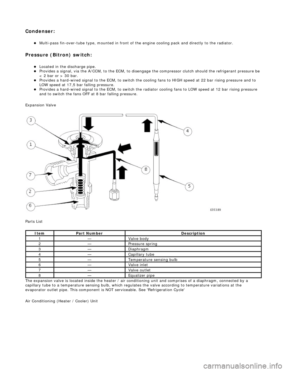
Expansion Valve
Parts List
The expansion valve is located inside the heater / air conditioning unit and comprises of a diaphragm, connected by a
capillary tube to a temperat ure sensing bulb, which regulates the valve according to temperature variations at the
evaporator outlet pipe. This component is NOT serviceable. See 'Refrigeration Cycle'
Air Conditioning (Heater / Cooler) Unit
ItemPart NumberDescription
1—Valve body
2—Pressure spring
3—Diaphragm
4—Capillary tube
5—Temperature sensing bulb
6—Valve inlet
7—Valve outlet
8—Equalizer pipe
Page 1856 of 2490
Instrument Cluster - Ins
trument Cluster
D
iagn
osis and Testing
Tests U
s
ing the Portable Diagnostic Unit
Re
fe
r to PDU User Guide
The c
o
mplexity of the electronics involved with the Instrument Cluster and the two multiplexed communication networks
which are connected to it, preclude the use of workshop genera l electrical test equipment. Therefore, reference should be
made to the PDU User Guide for detailed instructions on testing the Instrument Clus ter and associated circuits.
The PDU systematically test s and analyses all functions of the Instrument Clus ter, the various systems controlled by it and
individual sensors which are attached to each separate system.
Where a fault involving a remote sensor e. g. water temperature sensor, is indicated, before replacing the component, some
basic diagnostic methods may be necessary to confirm that connections are good and that wiring is not damaged.
Diagnostics using the PDU is via the CAN network, accessed at the diagnostic connector on the car.
Replaceable Parts
The only replaceable part s
are, General Illumination Bulbs, Direction Indicator Warning Bu
lbs and Main Beam Warning Bulb,
which are all of the conventional filament type. Other warning lamps are LEDs and are not replaceable.
Page 1885 of 2490
If the field were not controlled, the 'B+' output would rise to a level which could damage bulbs and ECMs. The regulator
compares the output voltage to an intern al voltage reference circuit to achieve the controlled output of the generator.
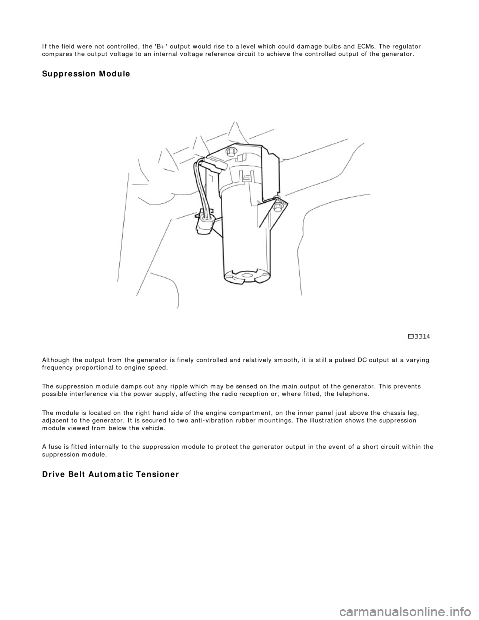
Suppression Module
Although the output from the generator is fi nely controlled and relatively smooth, it is still a pulsed DC output at a varying
frequency proportional to engine speed.
The suppression module damps ou t any ripple which may be sensed on the main output of the generator. This prevents
possible interference via the power supply, affecting the radio reception or, where fitted, the telephone.
The module is located on the right hand side of the engine compartment, on the inner panel just above the chassis leg,
adjacent to the generator. It is secured to two anti-vibration rubber moun tings. The illustration shows the suppression
module viewed from below the vehicle.
A fuse is fitted internally to the suppression module to protect the generator output in the event of a short circuit within th e
suppression module.
Drive Belt Automatic Tensioner
Page 1918 of 2490
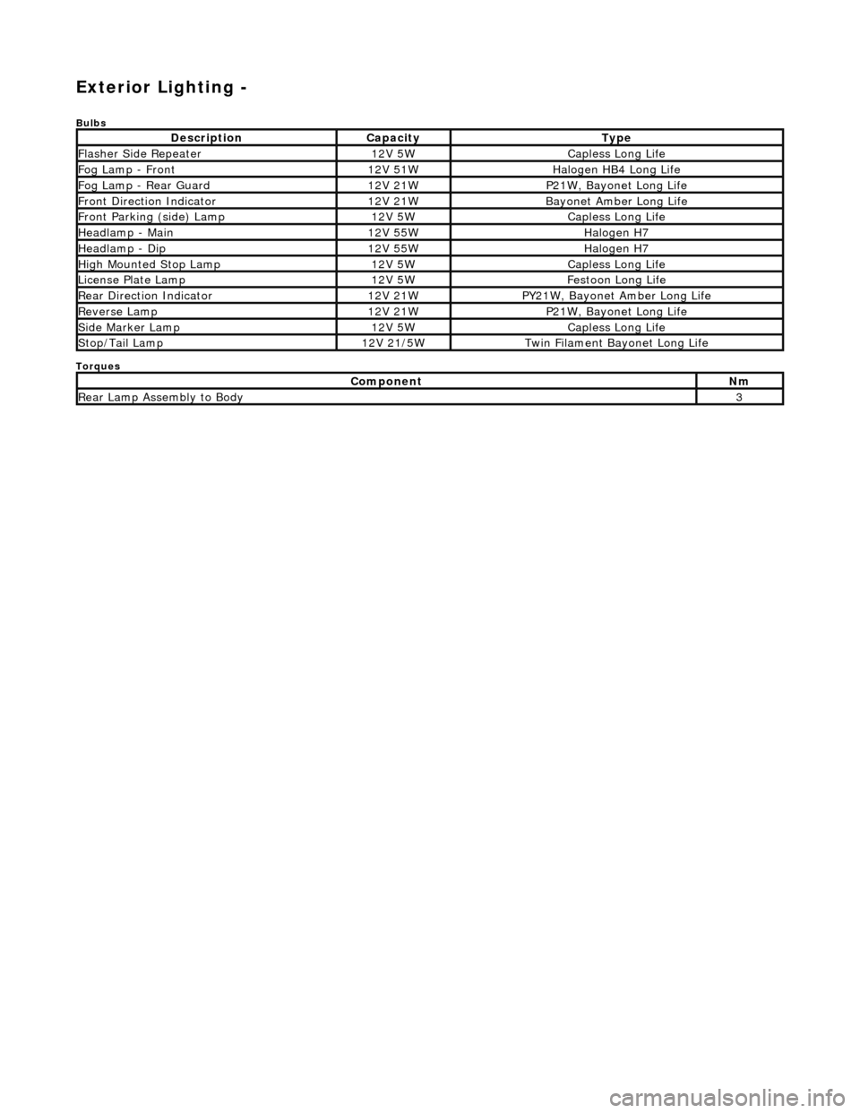
Exterior Lighting -
Bulbs
Torques
DescriptionCapacityType
Flasher Side Repeater12V 5WCapless Long Life
Fog Lamp - Front12V 51WHalogen HB4 Long Life
Fog Lamp - Rear Guard12V 21WP21W, Bayonet Long Life
Front Direction Indicator12V 21WBayonet Amber Long Life
Front Parking (side) Lamp12V 5WCapless Long Life
Headlamp - Main12V 55WHalogen H7
Headlamp - Dip12V 55WHalogen H7
High Mounted Stop Lamp12V 5WCapless Long Life
License Plate Lamp12V 5WFestoon Long Life
Rear Direction Indicator12V 21WPY21W, Bayonet Amber Long Life
Reverse Lamp12V 21WP21W, Bayonet Long Life
Side Marker Lamp12V 5WCapless Long Life
Stop/Tail Lamp12V 21/5WTwin Filament Bayonet Long Life
ComponentNm
Rear Lamp Assembly to Body3
Page 1919 of 2490
Exterior Lighting - Exterior Lighting
Description and Operation
A multi-function switch located on the left stalk of the steering column switch assembly permits selection of either parking
(side), headlamps, auto-headlamp or off. Selection of a particular mode provides the appropriate input to the body
processor module (BPM).
Where the auto headlamp function is incorporated, a light sensor in the interior rear view mirror monitors ambient light and
provides an input to the BPM. The BPM responds by switching the low beam headlamps on or off as appropriate for the
prevailing light conditions.
The front and rear fog lamp switch is located on the fascia outboard of the steering column.
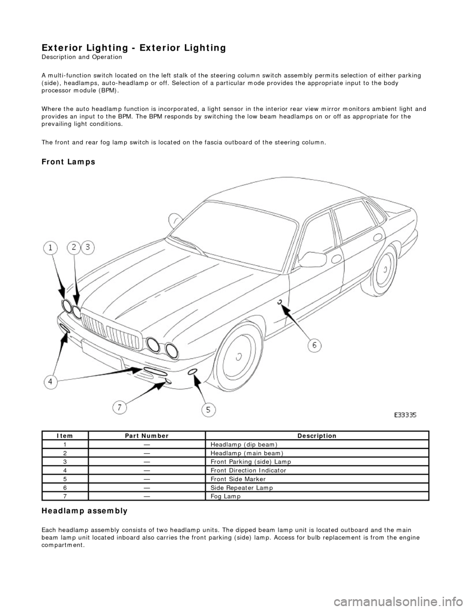
Front Lamps
Headlamp assembly
Each headlamp assembly consists of tw o headlamp units. The dipped beam lamp unit is located outboard and the main
beam lamp unit located inboard also carries the front parking (side) lamp. Access for bulb replacement is from the engine
compartment.
ItemPart NumberDescription
1—Headlamp (dip beam)
2—Headlamp (main beam)
3—Front Parking (side) Lamp
4—Front Direction Indicator
5—Front Side Marker
6—Side Repeater Lamp
7—Fog Lamp
Page 1921 of 2490
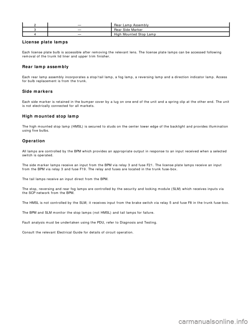
License plate lamps
Each license plate bulb is accessible after removing the relevant lens. The license plate lamps can be accessed following
removal of the trunk lid liner and upper trim finisher.
Rear lamp assembly
Each rear lamp assembly incorporates a stop/tail lamp, a fog lamp, a reversing lamp and a direction indicator lamp. Access
for bulb replacement is from the trunk.
Side markers
Each side marker is retained in the bumper cover by a lug on one end of the unit and a spring clip at the other end. The unit is not electrically connected for all markets.
High mounted stop lamp
The high mounted stop lamp (HMSL) is secu red to studs on the center lower edge of the backlight and provides illumination
using five bulbs.
Operation
All lamps are controlled by the BPM which pr ovides an appropriate output in response to an input received when a selected
switch is operated.
The side marker lamps receive an input from the BPM via relay 3 and fuse F21. The license plate lamps receive an input
from the BPM via relay 3 and fuse F19. The rela y and fuses are located in the trunk fuse-box.
The tail lamps receive an input direct from the BPM.
The stop, reversing and rear fog lamps are controlled by the security and locking module (SLM) which receives inputs via
the SCP network from the BPM.
The HMSL is not controlled by the SLM; it receives input from the brake switch via relay 5 and fuse F8 in the trunk fuse-box.
The BPM and SLM monitor the stop lamps (n ot HMSL) and tail lamps for failure.
Fault analysis must be undertaken using the PDU, refer to Diagnosis and Testing.
Consult the relevant Electrical Guid e for details of circuit operation.
2—Rear Lamp Assembly
3—Rear Side Marker
4—High Mounted Stop Lamp