center console JAGUAR X308 1998 2.G Workshop Manual
[x] Cancel search | Manufacturer: JAGUAR, Model Year: 1998, Model line: X308, Model: JAGUAR X308 1998 2.GPages: 2490, PDF Size: 69.81 MB
Page 432 of 2490

It is a reciprocating two
-circuit pu
mp in which one brake circuit is as signed to each pump circuit.
It supplies th
e fluid pressure and vo
lume to supply the brake circuits under ABS and Traction control.
The pump is driven by an electri
c motor, with the pump
housing incorporating two lo w pressure accumulators and
damping chambers for each brake circuit.
The ac cu
mulator stores the pressure and smooths out the output pu
lses from the pump.
ABS Warning Lamp
The sys
tem will be set in a fail-safe mode if a problem is de
tected; a warning lamp on the instrument panel will notify the
driver there is a problem.
Anti-Lock Braking Sy
stem (ABS)
The AB
S components are combined with
an hydraulic booster and a tandem master cylinder to provide a two circuit braking
system. The system comprises, four wheel speed sensor s, a brake control modulator and an ABS warning lamp.
Should a wheel start to lock-up during braking a signal tr ansmitted from the wheel speed sensor to the brake control
modulator will start the hydraulic pump. The brake control modula tor will close the input valve of the line connected to the
locked-wheel to stop any increase in fluid pressure to the br ake caliper. If this fails to prevent the wheel locking, the
pressure in the caliper will be decreased by opening the return valve until th e wheel starts accelerating again. The fluid
pressure from the return va lve is directed into the low pressure accumulator, housed in the pump.
From the low pressure accumulator, fl uid is pumped through the damping cham ber to the brake master cylinder. The
pressure to the brake caliper will then be increased in small steps to maintain maximum adhesion between the tire and road
surface. This is achieved by closing the return valve, and opening the input valve and using the hydraulic pump to increase
the pressure.
Although the system senses all four wheels independently, the rear wheels are regulated as a pair. If a sensor on a rear
wheel detects a wheel decelerating rapidly, then the fluid pressure to both wheels is reduced. The fluid pressure is then
dictated by the wheel having the lowe st adhesion with the road surface.
The ABS system will be set in a fail-safe mode if a problem is detected; a warn ing lamp on the instrument panel will notify
the driver there is a problem. The brake system will still operate conventionally and with the same standard of performance
as a vehicle not equipped with ABS.
Automa tic Stability Control (ASC)
Th
e ASC utilizes the ABS sensing arrangement to provide the maximum traction force to propel the vehicle.
The ASC is switched on when the engine is started. The system can be switched off by pressing the 'ASC OFF' (the switched
is marked 'TRAC OFF' on vehicles fitted with traction control). The switch, which is situated in the center console switchpack,
lights up to warn that the system is sw itched off. An 'ASC' amber warning light flashes on the instrument panel when the
system detects a spinning wheel.
The ASC system uses engine intervention to reduce the torque delivered to the drive wheels to prevent them spinning.
Engine torque is re duced in three ways:
The
throttle is moved towards the closed position.
The ignition is retarded. F
u
el is cut-off at the cylinder injectors.
Wheel spin is detected by the wheel sp eed sensors and communicated to the AB S/TCCM. The ABS/TCCM uses information
from the controller area network (CAN) to calculate the torque that the engine should produce to stop the wheel spinning.
Torque reductions are then requested from the engine control module (ECM ) through the CAN. The throttle is then
positioned to provide the target torque, which has been calculated to prevent wheel spin. During the transient phase of
torque reduction the fuel is cut-off and th e ignition retarded Both the fuel cut-off an d ignition retard will be restored to
normal when the throttle is set to its new position.
The ASC uses a brake control modulator with six solenoid va lves: three normally open inlet valves and three normally
Page 1482 of 2490

Automatic Transmission/Transaxle External Controls - 4.0L NA V8 -
AJ27/3.2L NA V8 - AJ 26 - Selector Lever Cable Adjustment
General Procedures
1. Disconnect battery ground cable.
Remove the battery cover.
2. Position the shift to N.
3. Remove the J-gate surround, Section 501-05.
4. Remove the console finisher ve neer panel, Section 501-12.
5. Remove the center console assembly, Section 501-12.
6. Slacken the selector cable locking nuts away from the
abutment.
7. Raise the vehicle for access.
8. Verify the transmission selector position ( N )
1. At the transmission, detach the inner cable from the selector lever.
2. With the lever moved fully rearward, push the lever forward two detents to achieve N.
3. Reconnect the inner cable.
9. From inside the vehicle.
10. NOTE: When setting the selector cable, ensure that the
transmission selector does not move from the N position.
Adjust the selector cable. 1. Position the shift in the N detent
2. Adjust the nuts to lock against the bracket without
Page 1487 of 2490

Automatic Transmission/Transaxle External Controls - 4.0L NA V8 -
AJ27/3.2L NA V8 - AJ 26 - Selector Lever Cable and Bracket
Removal and Installation
Removal
1. Position the selector to N.
2. Remove the J-gate surround, Section 501-05.
3. Remove the console finisher ve neer panel, Section 501-12.
4. Remove the center console assembly, Section 501-12.
5. Raise the vehicle for access.
6. Detach the selector cable from the transmission unit.
1. Remove the cable inner to selector lever nut.
2. Remove the cable to transmission casing fixings.
7. Reposition the selector cable.
8. Remove the LH front seat, Section 501-10.
9. Reposition the LH floo r carpet for access.
10. Remove the selector cable to tunnel clip tie strap.
11. Detach the selector cable from the gear shift assembly.
1. Remove the inner cable to shift lever nut.
2. Slacken the outer cable locknuts.
Page 1495 of 2490

Automatic Transmission/Transaxle External Controls - 4.0L NA V8 -
AJ27/3.2L NA V8 - AJ26 - Selector Lever Assembly
Disassembly and Assembly
1. Disconnect battery ground cable.
Remove the battery cover.
2. Remove the shift le ver knob, 44.15.06.
3. Remove the J-gate surround, Section 501-05.
4. Remove the console finisher ve neer panel, Section 501-12.
5. Remove the center console assembly, Section 501-12.
6. Remove the indicator module, 44.15.14.
7. Detach the selector cable from the gear shift assembly.
1. Remove the inner cable to selector lever nut.
2. Slacken one outer cable locknut, keeping one positioned for reference on reassembly.
8. Remove the gear shift assembly.
Remove the four fixings.
9. Remove the slide plate.
Remove the four screws.
Page 1510 of 2490

Automatic Transmission/Transaxle External Contro ls - 4.0L SC V8 - AJ26 -
Selector Lever Cable Adjustment
General Procedures
1.
Disconnect the vehicle battery ground lead.
2. Position the gear sele ctor lever to N.
3. Remove the J-gate surround, Section 501-05.
4. Remove the console finisher ve neer panel, Section 501-12.
5. Remove the center console assembly, Section 501-12.
6. Slacken the selector cable lock ing nuts and screw them away
from the abutment.
7. Raise the vehicle for access.
8. Verify that the transmis sion selector lever is at position ( N ).
At the transmission, detach the inner cable from the
selector lever.
With the lever moved fully rearward, push the lever
forward two detents to achieve N.
1. Reconnect the inner cable.
9. NOTE: When setting the selector cable, ensure that the
transmission selector does no t move from the (N) position.
Adjust the selector cable from inside the vehicle. 1. Position the gear select or lever to the N detent.
2. Adjust the nuts to lock against the bracket without moving the set position of either the gear selector
lever or the select or lever on the transmission case.
3. Tighten to specification.
4. Verify the ( N ) setting.
10. Further installation is the reve rse of the removal procedure.
Page 1513 of 2490

Automatic Transmission/Transaxle External Contro ls - 4.0L SC V8 - AJ26 -
Selector Lever Cable and Bracket
Removal and Installation
Removal
1. Disconnect the vehicle battery ground lead.
2. Position the selector to N.
3. Remove the J-gate surround, Section 501-05.
4. Remove the console finisher ve neer panel, Section 501-12.
5. Remove the center console assembly, Section 501-12.
6. Raise the vehicle for access.
7. Detach the gear selector cable from the transmission unit.
1. Remove the nut which secures the selector cable ball pin to the selector lever.
2. Lower the transmissi on lift for access.
3. Remove the bolts which secure the selector cable to the transmission casing.
8. Reposition the selector cable.
9. Remove the LH front seat, Section 501-10.
10. Reposition the LH floo r carpet for access.
11. Remove the selector cable to tunnel clip tie strap.
12. Detach the selector cable from the gear shift assembly.
1. Remove the inner cable to shift lever nut.
Page 1821 of 2490

Control Components - Control Components
Description and Operation
System Controls
The climate control system is controlled by : 1. 1. Manual input from the operator, via the center console located control panel.
2. 2. Automatically by means of the A/CCM.
Output is based upon input from the following devices:
Motorized In-car aspirator External air temperature sensor Coolant temperature sensor Heater 'air-off' (the temperature of the air leaving the matrix fins) temperature sensor Evaporator 'air-off' (the temperature of the air leaving the evaporator fins) temperature sensor Solar sensor Left hand blower recirculation / fresh air flap potentiometer Right hand blower recirculation / fresh air flap potentiometer Upper air distribution box (ADB) center and side face flap servomotor potentiometer ADB defrost flap servomotor potentiometer Air conditioning unit Foot flap servomotor potentiometer Air conditioning unit Cool Air Bypass flap servomotor potentiometer Thumbwheel controls on the facia vent assemblies which provide manu al adjustment of the airflow volume. Road and engine speed signals input to the A/CCM
Climate Control Panel
Communication between the control panel and the A/CCM is via a serial data communications link.
Switching the Climate Control system ON
The climate control system can be switched ON by pressing one of the following :
Ref #1 On / Off (resumes the system on in the previous settings).
Ref #10 A / C (resumes the system on in the previous settings).
Ref #11 AUTO (resumes the system on at the previous temperature setting).
Page 2006 of 2490

Multifunction Electronic Modules - Module Controlled Functions
Description and Operation
Body Processor Module (BPM)
ItemPart NumberDescription
1—Body Processor Module
2—Front Door Control Module
3—Rear Door Control Module
4—Roof Console Switch Module
5—Center Console Switch Module
Page 2011 of 2490

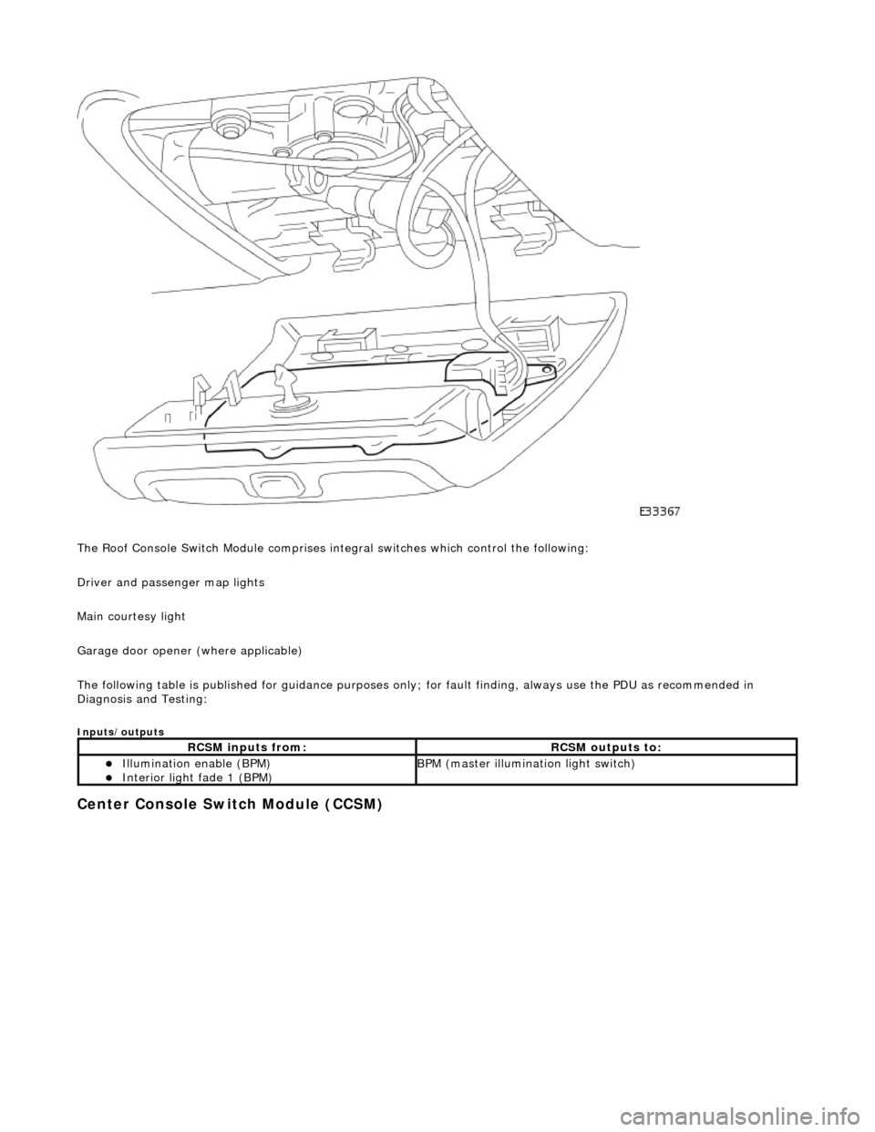
The Roof Console Switch Module comprises integral switches which control the following:
Driver and passenger map lights
Main courtesy light
Garage door opener (where applicable)
The following table is published for guidance purp oses only; for fault finding, always use the PDU as recommended in
Diagnosis and Testing:
Inputs/outputs
Center Console Switch Module (CCSM)
RCSM inputs from:RCSM outputs to:
Illumination enable (BPM) Interior light fade 1 (BPM) BPM (master illumination light switch)
Page 2012 of 2490

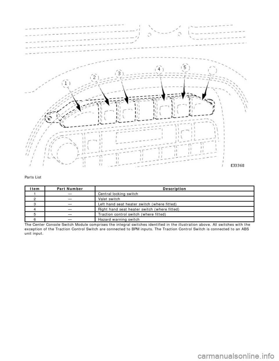
Parts List
The Center Console Switch Module comprises the integral switches identified in the illustration above. All switches with the
exception of the Traction Control Switch are connected to BPM inputs. The Traction Control Switch is connected to an ABS
unit input.
ItemPart NumberDescription
1—Central locking switch
2—Valet switch
3—Left hand seat heater switch (where fitted)
4—Right hand seat heater switch (where fitted)
5—Traction control switch (where fitted)
6—Hazard warning switch