gearbox mount JAGUAR X308 1998 2.G Workshop Manual
[x] Cancel search | Manufacturer: JAGUAR, Model Year: 1998, Model line: X308, Model: JAGUAR X308 1998 2.GPages: 2490, PDF Size: 69.81 MB
Page 1522 of 2490

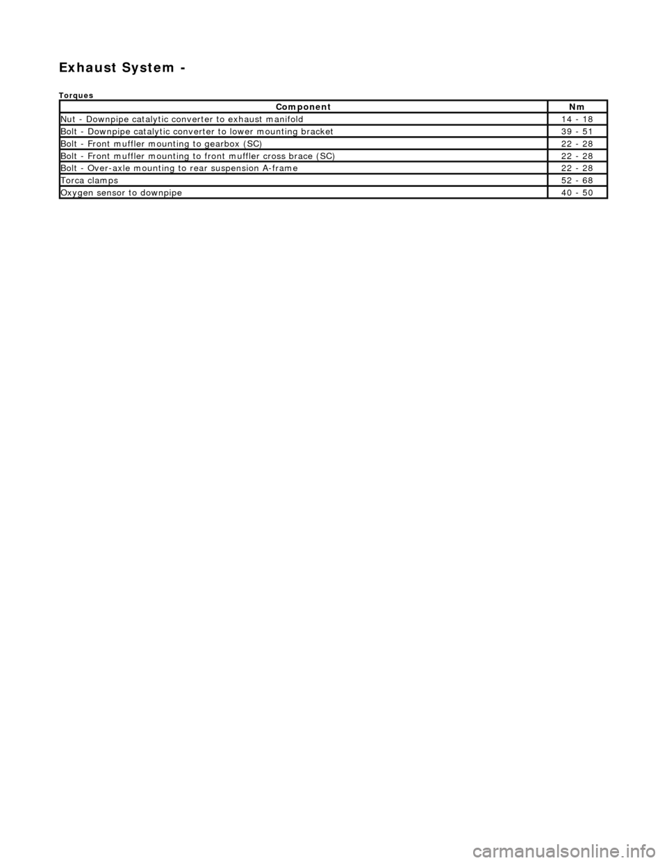
Exhaust System -
Torques
ComponentNm
Nut - Downpipe catalytic converter to exhaust manifold14 - 18
Bolt - Downpipe catalytic converter to lower mounting bracket39 - 51
Bolt - Front muffler mounting to gearbox (SC)22 - 28
Bolt - Front muffler mounting to front muffler cross brace (SC)22 - 28
Bolt - Over-axle mounting to rear suspension A-frame22 - 28
Torca clamps52 - 68
Oxygen sensor to downpipe40 - 50
Page 1670 of 2490

Ex
haust System - Front Muffler4.0L SC V8 - AJ26
Re
mo
val and Installation
Remov
a
l
Installation
1. Ra
ise the vehicle on a ramp.
2. Separate the front muf f
ler flan
ge joints from the downpipe
catalytic converters.
Slac ken t
he flange nuts (left-hand and right-hand sides),
catalytic converter to front muffler.
3. Slacken the clamps (left-ha nd and right-hand sides),
i
ntermediate mufflers to front muffler.
Move both i
n
termediate mufflers rearwards, as far as
possible.
4. Remove the flange nuts (lef t-hand and right-hand sides),
catalytic converter to front muffler.
5. Re
move the bolts which secure th
e front muffler rear mounting
to the rear of the gearbox.
6. Remove the front muffler.
Di
sconnect the front muffler fr
om each downpipe flange.
Di
sconnect the front muffler
from the intermediate
mufflers and remove it.
7. Remove the gasket from each front flange joint.
8. Clean and inspect al l exhaust joints.
1. Fit the front muffler.
Page 1671 of 2490

F
it the front muffler fully into
the intermediate mufflers.
2. Con
nect the front muffler flanges to the catalytic converters.
F
it a new gasket to each flange.
Con
nect the front muffler flanges to the catalytic
converters; move the front muffler / intermediate
mufflers assembly forwards.
Tigh
ten the flange nuts (left-hand and right-hand sides),
front muffler to catalytic converters.
3. F
it the bolts which secure the front muffler rear mounting to
the rear of the gearbox.
4. Re
position the intermediate mu
fflers to the front muffler to
align the correct referenc e / index indicator ring.
Ti
ghten the clamps (left-han
d and right-hand sides),
intermediate mufflers to front muffler.
5. Lower the ramp.
Page 2145 of 2490

Installation
8. Using a suitable soft drift, release drive shaft from gearbox and potentiometer.
9. Slacken and remove bolts securi ng potentiometer/gearbox to
seat frame
10. Rotate potentiometer to release it from retaining plate tang.
11. Slacken and remove bolts securing recline motor to seat
frame.
12. Remove recline motor/potentio meter/gearbox assembly from
seat.
1. Position recline motor on seat frame mounting and fit and
Page 2148 of 2490

Installation
8. Withdraw LH slide from seat motor potentiometer/gearbox
assembly.
1. Fit and fully seat slide to po tentiometer/gearbox assembly.
2. Position motor frame on slide assembly and secure with new
pop rivets.
3. Connect seat cushion tilt motor drive cables.
4. Secure seat harness in clips.
5. Position slide assembly on seat.
6. Fit and align RH seat belt bu ckle mounting bracket between
slide and seat pivot bracket and fit but do not tighten securing
bolts.
7. Fit and align LH seat belt an chor bracket between slide and
seat pivot bracket an d fit but do not tighten securing bolts.
8. Fit but do not tighten RH and LH slide front securing bolts.
9. Finally tighten slide front and rear securing bolts.
10. Fit front seat to vehi cle. Refer to 76.70.01.
Page 2152 of 2490

16. Slacken and remove bolt securi ng motor/ potentiometer and
gearbox to LH slider and re move LH slider assembly.
17. Release motor/potentiometer an d gearbox harness multiplug
from mounting bracket an d disconnect multiplug.
18. Slacken and remove motor/pote ntiometer to frame securing
bolts.
19. Disconnect RH seat slider gearbox drive cable from
motor/potentiometer.
Page 2153 of 2490

I
nstallation
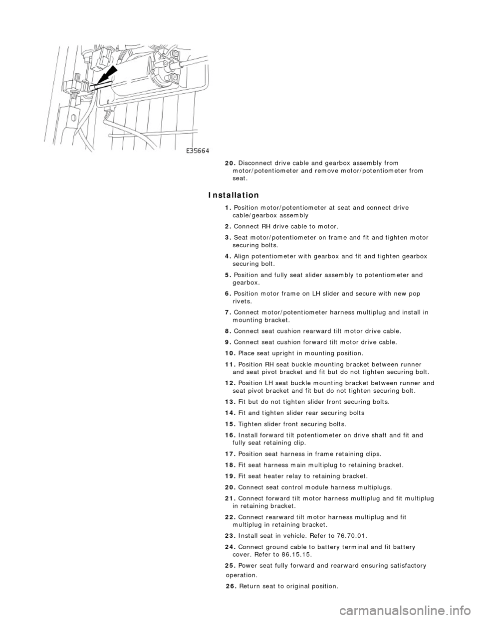
20
.
Disconnect drive cable and gearbox assembly from
motor/potentiometer and remo ve motor/potentiometer from
seat.
1. Position motor/potentiometer at seat and connect drive
cable/gearbox assembly
2. Connect RH drive cable to motor.
3. Seat motor/potentiometer on fra me and fit and tighten motor
securing bolts.
4. Align potentiometer with gearbo x and fit and tighten gearbox
securing bolt.
5. Position and fully seat slider assembly to potentiometer and
gearbox.
6. Position motor frame on LH sl ider and secure with new pop
rivets.
7. Connect motor/potentiometer harness multiplug and install in
mounting bracket.
8. Connect seat cushion rearward tilt motor drive cable.
9. Connect seat cushion forwar d tilt motor drive cable.
10. Place seat upright in mounting position.
11. Position RH seat buckle mounting bracket between runner
and seat pivot bracket and fit but do not tighten securing bolt.
12. Position LH seat buckle mounting bracket between runner and
seat pivot bracket an d fit but do not tighten securing bolt.
13. Fit but do not tighten slider front securing bolts.
14. Fit and tighten slider rear securing bolts
15. Tighten slider front securing bolts.
16. Install forward tilt potentiome ter on drive shaft and fit and
fully seat retaining clip.
17. Position seat harness in frame retaining clips.
18. Fit seat harness main multiplug to retaining bracket.
19. Fit seat heater relay to retaining bracket.
20. Connect seat control module harness multiplugs.
21. Connect forward tilt motor harn ess multiplug and fit multiplug
in retaining bracket.
22. Connect rearward tilt motor harness multiplug and fit
multiplug in retaining bracket.
23. Install seat in vehicle. Refer to 76.70.01.
24. Connect ground cable to batt ery terminal and fit battery
cover. Refer to 86.15.15.
25. Power seat fully forward and rearward ensuring satisfactory
op
eration.
26. Return seat to original position.