flat tire JAGUAR X308 1998 2.G Workshop Manual
[x] Cancel search | Manufacturer: JAGUAR, Model Year: 1998, Model line: X308, Model: JAGUAR X308 1998 2.GPages: 2490, PDF Size: 69.81 MB
Page 59 of 2490
Al
l the above figures
are at "showroom" height. (See ride height section above).
Ti
res must be inflated
to normal pressure.
For additional informat ion, refer to Section 204
-0
4 Wheels and Tires
.
Whe
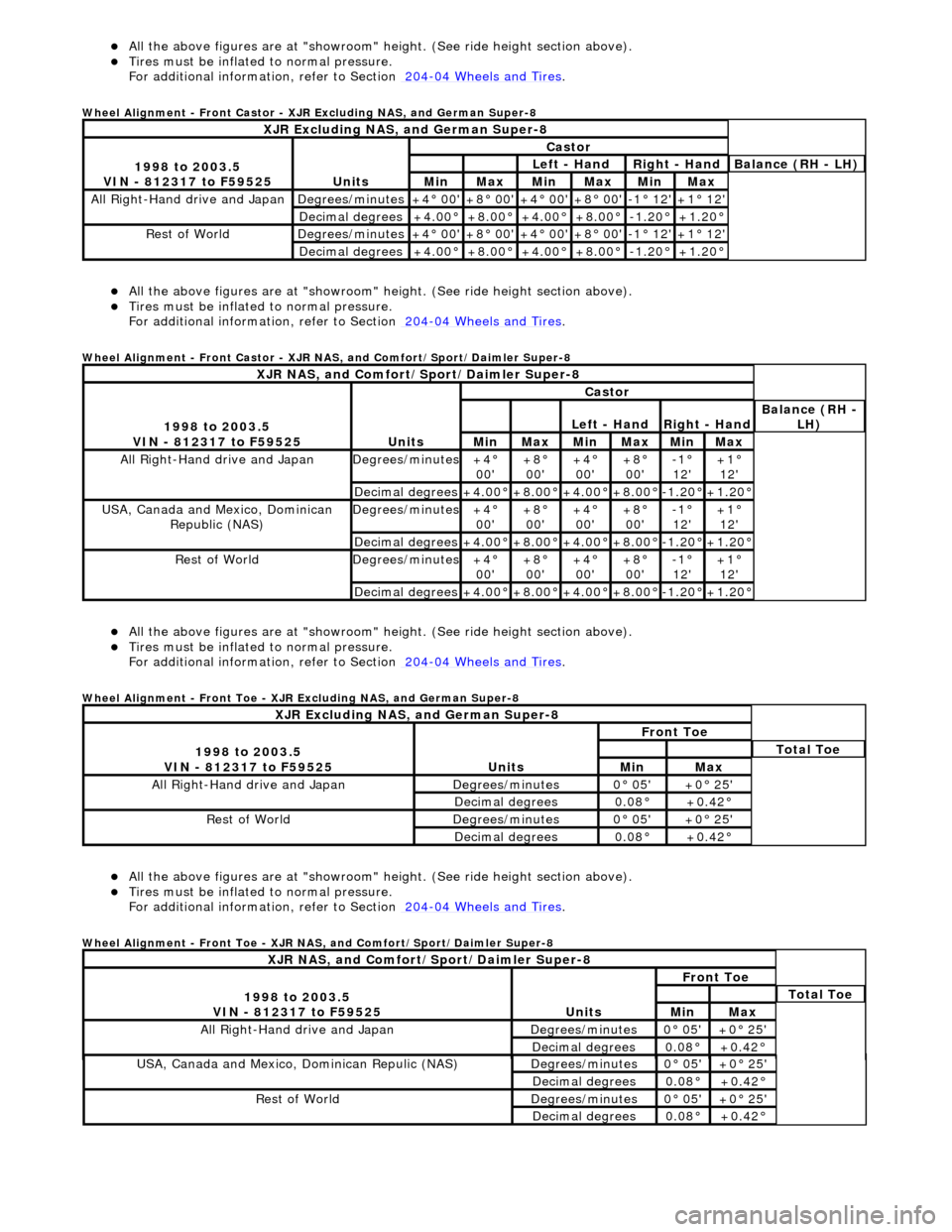
el Alignment - Front Castor - XJR Excluding NAS, and German Super-8
Al
l the above figures
are at "showroom" height. (See ride height section above).
Ti
res must be inflated
to normal pressure.
For additional informat ion, refer to Section 204
-0
4 Wheels and Tires
.
Whe
el Alignment - Front Castor - XJR NAS, and Comfort/Sport/Daimler Super-8
Al
l the above figures
are at "showroom" height. (See ride height section above).
Ti
res must be inflated
to normal pressure.
For additional informat ion, refer to Section 204
-0
4 Wheels and Tires
.
Whe
el Alignment - Front Toe - XJR Excluding NAS, and German Super-8
Al
l the above figures
are at "showroom" height. (See ride height section above).
Ti
res must be inflated
to normal pressure.
For additional informat ion, refer to Section 204
-0
4 Wheels and Tires
.
Whe
el Alignment - Front Toe - XJR NAS, and Comfort/Sport/Daimler Super-8
XJR
Excluding NAS, and German Super-8
1
998 to 2003.5
VIN - 812317 to F59525
Units
Castor
Le
ft - Hand
Rig
ht - Hand
Bal
ance (RH - LH)
MinMaxMinMaxMinMax
All Right
-Hand drive and Japan
De
grees/minutes
+4
° 00'
+8
° 00'
+4
° 00'
+8
° 00'
-1
° 12'
+1
° 12'
Decimal degrees+4
.00°
+8
.00°
+4
.00°
+8
.00°
-1.
20°
+1
.20°
R
est of World
De
grees/minutes
+4
° 00'
+8
° 00'
+4
° 00'
+8
° 00'
-1
° 12'
+1
° 12'
Decimal degrees+4
.00°
+8
.00°
+4
.00°
+8
.00°
-1.
20°
+1
.20°
XJR
NAS, and Comfort/Sport/Daimler Super-8
1
998 to 2003.5
VIN - 812317 to F59525
Units
Castor
Le
ft - Hand
Rig
ht - Hand
Bal
ance (RH -
LH)
MinMaxMinMaxMinMax
All Right
-Hand drive and Japan
De
grees/minutes
+4
°
00'
+8
°
00'
+4
°
00'
+8
°
00'
-1
°
12'
+1
°
12'
Decimal degrees+4
.00°
+8
.00°
+4
.00°
+8
.00°
-1.
20°
+1
.20°
USA, Canada an
d Mexico, Dominican
Republic (NAS)
De
grees/minutes
+4
°
00'
+8
°
00'
+4
°
00'
+8
°
00'
-1
°
12'
+1
°
12'
Decimal degrees+4
.00°
+8
.00°
+4
.00°
+8
.00°
-1.
20°
+1
.20°
R
est of World
De
grees/minutes
+4
°
00'
+8
°
00'
+4
°
00'
+8
°
00'
-1
°
12'
+1
°
12'
Decimal degrees+4
.00°
+8
.00°
+4
.00°
+8
.00°
-1.
20°
+1
.20°
XJR
Excluding NAS, and German Super-8
1
998 to 2003.5
VIN - 812317 to F59525
Units
Fr
ont Toe
To
tal Toe
MinMax
All Right-Hand driv
e and Japan
De
grees/minutes
0
° 05'
+0
° 25'
Decimal degrees0.
08°
+0
.42°
R
est of World
De
grees/minutes
0
° 05'
+0
° 25'
Decimal degrees0.
08°
+0
.42°
XJR
NAS, and Comfort/Sport/Daimler Super-8
1
998 to 2003.5
VIN - 812317 to F59525
Units
Fr
ont Toe
To
tal Toe
MinMax
All Right-Hand driv
e and Japan
De
grees/minutes
0
° 05'
+0
° 25'
Decimal degrees0.
08°
+0
.42°
USA, Canada an
d Mexico
, Dominican Repulic (NAS)
De
grees/minutes
0
° 05'
+0
° 25'
Decimal degrees0.
08°
+0
.42°
R
est of World
De
grees/minutes
0
° 05'
+0
° 25'
Decimal degrees0.
08°
+0
.42°
Page 61 of 2490
Suspension System - General Information - Front Camber and Caster
Adjust
ment
Gen
eral Procedures
• NOTE: Before any work is commenced, th e vehicle must be checked to establish that it conforms to the Jaguar original
specification, e.g. wheels, ti res, tire pressures, etc.
• NOTE: The vehicle must be unladen and the fuel tank full when measuring suspension geometry.
1.
Road test the vehicle to establish the exact nature of the
complaint, e.g. pulling to one side, wander.
2. Measure the suspension geometry, fill in the 'Suspension
Geometry Record Form', and co ntact Jaguar Technical Support
for assistance.
3. Technical Support will give advice on the course of action to be
taken to rectify the problem.
4. Each lower wishbone pivots on and is secured to the front
crossbeam by two fulcrum bolts. A circular eccentric flange
formed under the hexagonal head of each fulcrum bolt, has
raised graduation marks to indicate radial position. A washer
with a 'D' shaped hole locates on a flat on the threaded section
of each bolt. This ensures that the washer rotates with the bolt,
maintaining an eccentric position corresponding with the
flanged head. The outer face of the washer is punch marked,
ensuring correct instal lation with the chamfered face inwards.
This permits the washer to rotate freely in the crossbeam cam
reaction plate during a djustm ent. Each fulcrum bolt and
washer are secured by a self locking nut.
On rotation of the bolt, lateral movement of the eccentric flange
and washer is restricted by the cam plate faces, forcing the bolt
shank to move laterally in the crossbeam slots. Lateral
movement of the bolt shank re sults in corresponding inward
and outward movement of th e wishbone arm, effecting
adjustment of wh eel alignment.
Rotation of the front fulcrum bolt principally adjusts wheel
caster angle, with a small amount of camber angle change.
Adjustment of the rear fulcrum bo lt mainly alters wheel camber
angle with a small amount of caster angle change.
On vehicles with VIN up to 833124, fulcrum bolt eccentric
flanges have raised graduation marks representing 15 degree
increments of bolt rotati on from 0 to 90 degrees.
On vehicles with VIN from 833125, the fulcrum bolt graduation
marks represent bolt shank ho rizontal movement in 1mm
increments from 0 to 3mm.
The upper wishbone and fulcrum shaft are not adjustable and
play no part in steering geometry adjustment.
Page 106 of 2490
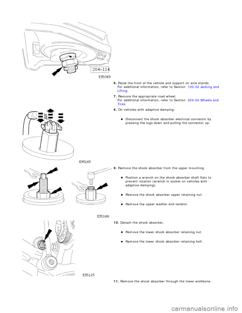
6. Ra
ise the front of the vehicle
and support on axle stands.
For additional informat ion, refer to Section 100
-02
Jacking and
Liftin
g.
7. Re
move the appropriate road wheel.
For additional informat ion, refer to Section 204
-04 W
heels and
Tire
s.
8. On
vehicles with adaptive damping:
Di
sc
onnect the shock absorber electrical connector by
pressing the lugs down and pulling the connector up.
9. Re
move the shock absorber from the upper mounting.
Posi
ti
on a wrench on the shock absorber shaft flats to
prevent rotation (wrench in socket on vehicles with
adaptive damping).
Re
move the shock absorber
upper retaining nut.
Remove the u
pper washer and isolator.
10 . De
tach the shock absorber.
R
e
move the lower shock ab
sorber retaining nut.
Re
move the lower shock ab
sorber retaining bolt.
11. Remove the shock absorber through the lower wishbone.
Page 259 of 2490
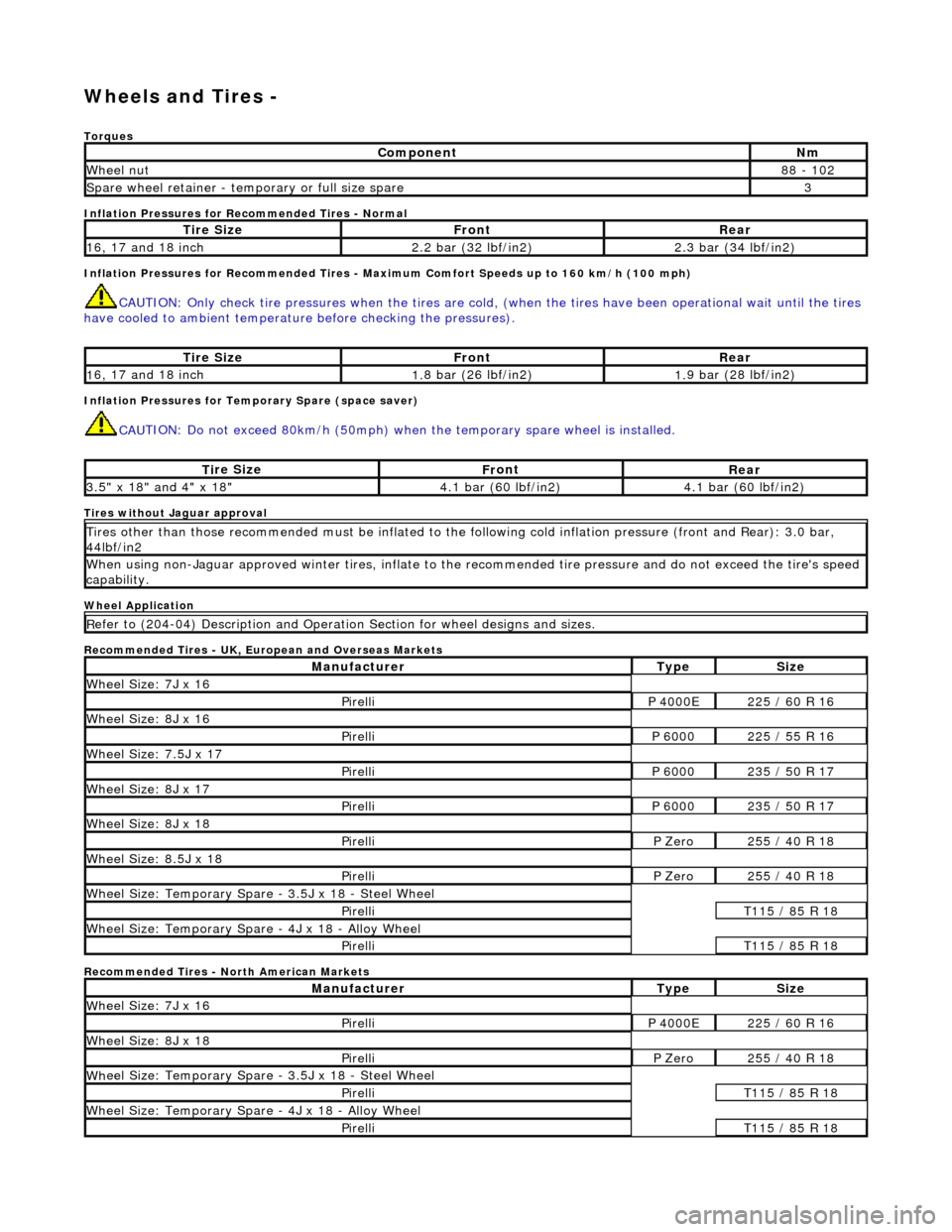
W
heels and Tires -
Torq
ues
Inflation Pressures for Recommended Tires - Normal
Inflation Pressures for Recommended Tires - Maxi mum Comfort Speeds up to 160 km/h (100 mph)
CAUTI
ON: Only check tire pressures when
the tires are cold, (when the tires have been operational wait until the tires
have cooled to ambient temperature before checking the pressures).
Inf
lation Pressures for Temporary Spare (space saver)
CAU
TION: Do not exceed 80km/h (50mph) when the temporary spare
wheel is installed.
Tires
without Jaguar approval
Wheel Application
Recommended Tires - UK, European and Overseas Markets
Recommended Tires - North American Markets
Com
ponent
Nm
Wh
eel nut
8
8 - 102
Spare wheel r
etainer - temporary or full size spare
3
Ti
re Size
Fr
ont
Rear
1
6, 17 and 18 inch
2.
2 bar (32 lbf/in2)
2.
3 bar (34 lbf/in2)
Ti
re Size
Fr
ont
Rear
1
6, 17 and 18 inch
1.
8 bar (26 lbf/in2)
1.
9 bar (28 lbf/in2)
Ti
re Size
Fr
ont
Rear
3.
5" x 18" and 4" x 18"
4.
1 bar (60 lbf/in2)
4.
1 bar (60 lbf/in2)
Ti
res other than those recommended must be inflated to the following cold
inflation pressure (front and Rear): 3.0 bar,
44lbf/in2
Wh
en using non-Jaguar approved winter ti
res, inflate to the recommended tire pressure and do not exceed the tire's speed
capability.
R
efer to (204-04) Description and Operation Section for wheel designs and sizes.
Manufact
urer
Ty
pe
Si
ze
W
heel Size: 7J x 16
Pire
lli
P 40
00E
2
25 / 60 R 16
W
heel Size: 8J x 16
Pire
lli
P 60
00
2
25 / 55 R 16
Wh
eel Size: 7.5J x 17
Pire
lli
P 60
00
2
35 / 50 R 17
W
heel Size: 8J x 17
Pire
lli
P 60
00
2
35 / 50 R 17
W
heel Size: 8J x 18
Pire
lli
P Ze
ro
2
55 / 40 R 18
Wh
eel Size: 8.5J x 18
Pire
lli
P Ze
ro
2
55 / 40 R 18
Wh
eel Size: Temporary Spare - 3.5J x 18 - Steel Wheel
Pire
lli
T1
15 / 85 R 18
W
heel Size: Temporary Spare - 4J x 18 - Alloy Wheel
Pire
lli
T1
15 / 85 R 18
Manufact
urer
Ty
pe
Si
ze
W
heel Size: 7J x 16
Pire
lli
P 40
00E
2
25 / 60 R 16
W
heel Size: 8J x 18
Pire
lli
P Ze
ro
2
55 / 40 R 18
Wh
eel Size: Temporary Spare - 3.5J x 18 - Steel Wheel
Pire
lli
T1
15 / 85 R 18
W
heel Size: Temporary Spare - 4J x 18 - Alloy Wheel
Pire
lli
T1
15 / 85 R 18
Page 263 of 2490
O
ne locking wheel nut is fitted to each road wheel and can on
ly be removed by using the correctly coded socket. For road
wheels with exposed wheel nuts, each locking wheel nut is provided with a cover, which is removed using the cover removal
tool.
Locking wheel nuts have different coded keyway combinations with corresponding coded sockets. The correct socket, and
cover removal tool are supplied with the vehicle toolkit. Sets of sockets are available to Jaguar dealers.
Temporary Spare Wheel
•
NOTE: When using this type of spare wheel note that:
Speed
must not exceed 80 km/h (50 mph).
The normal ro
ad wheel must be reinstalled as soon as possible.
On
ly one temporary wheel may be installed to the vehicle.
Tracti
on control (where fitted
) must be switched OFF.
In certain markets, the spare wheel supplied with the vehicle is of the temporary-use type, it is narrower than the normal
road wheel and takes up less room in the luggage compartment.
Tire
s
The
radial ply tires shown in the 204-04
Specification Section are recommended by Jaguar to meet the high speed
performance of the vehicle. Only tires of identical specification may be fitted as replacements. Unde r no circumstances must
cross-ply tires be fitted.
Tire Inflation Pressures
Al
l recommended tires, including winter tire
s, must be inflated to the pressures shown in the 204-04 Specification Section.
Inflation pressures must only be checked when the tires are cold.
Tire Replac
ement and Wheel-Interchanging
W
hen renewal of tires is necessary, it is
preferable to fit a complete set. If two replacement tires are fitted (to one axle),
they must be of the same manufacturer and type as those on the other axle.
No attempt must be made to interchange wh eels from the front to the rear or vice-versa, as wear produc es a characteristic
pattern on each tire depending upon its po sition on the vehicle. If this position is changed after wear has occurred, the
performance of the tire w ill be adversely affected.
It should be remembered that new tires must be balanced befo re installing to the vehicle.
Win
ter Tires
•
NOTE: Speed must not exceed 210 km/h (131 mph) when winter tires are installed.
Jaguar recommended winter tires as specified in 204-04 Specification Section must only be fitted in complete four-wheel
sets of the same type and size.
Snow Chains and Spike Spider Traction System
Jagu
ar recommended snow chains, must on
ly be installed when using 16 inch wheels with 255/60 R16 winter tires.
• NOTE: When using snow chains or the spike spider traction system, note that:
Snow ch
ains and the spike spider
traction system must only be fitted to the rear wheels.
O
nly Jaguar recommended snow chains and spik
e spider traction system must be used.
The m
aximum permissible speed with winter tires and snow chains or the spike spider traction system fitted is 48
km/h (30 mph).
Tracti
on control (where fitted) must be
switched OFF when using snow chains or the spike spider traction system.
Page 265 of 2490
W
heels and Tires - Wheels and Tires
D
iagnosis and Testing
General Not
es
1.
1. Factory in
stalled tires and wheels are designed to provide optimum ride and ha
ndling characteristics when inflated
to the recommended inflation pressures, with vehicle loads not exceeding the full-rated load capacity.
2. 2. Correct tire pressures and driv ing technique have an important influence on tire life. Heavy cornering, excessively
rapid acceleration and unnecessary sharp braking increase tire wear.
3. 3. Replacement tires should follow the recommended:
Size
.
Speed
rating.
Load range. Radial c
onstruction type.
4. 4. The use of any other size or type of wheel / tire may seriously affect:
Safety. Ri
de.
Handlin
g.
Speed
ometer / odometer calibration.
Vehi
cle ground clearance.
Ti
re clearance between
body and chassis.
Wh
eel bearing life.
Brake cooli
ng.
5. 5. Wheels must be renewed when:
Impact damaged. Heavil
y corroded.
Porous W
heel stud holes or se
ats become damaged.
They h
ave excessive radial or lateral runout.
Safety Notes
• WAR
NINGS:
DO NOT MIX DIFFERENT TYPES OF TIRES ON THE SAM E VEHICLE, HANDLING MAY BE SERIOUSLY AFFECTED
RESULTING IN LOSS OF CONTROL.
DO NOT MIX DIFFERENT TYPES OF TIRES ON THE SAM E VEHICLE, HANDLING MAY BE SERIOUSLY AFFECTED
RESULTING IN LOSS OF CONTROL.
A TIRE AND WHEEL MUST ALWAYS BE CORRECTLY MATCHED. WIDER OR NARROWER TIRES THAN RECOMMENDED
COULD CAUSE DANGER THROUGH SUDDEN DEFLATION.
WHEN USING THE TEMPORARY SPARE WHEEL, SPEED MUST NOT EXCEED 80 KM/H (50 MPH). DRIVE WITH CAUTION
AND REPLACE WITH THE SPECIFIED WHEEL / TIRE ASSEMBLY AS SOON AS POSSIBLE.
TRACTION CONTROL (IF AVAILABLE) MUST NOT BE ENGAGED WITH THE TEMPORARY SPARE WHEEL FITTED.
Page 267 of 2490
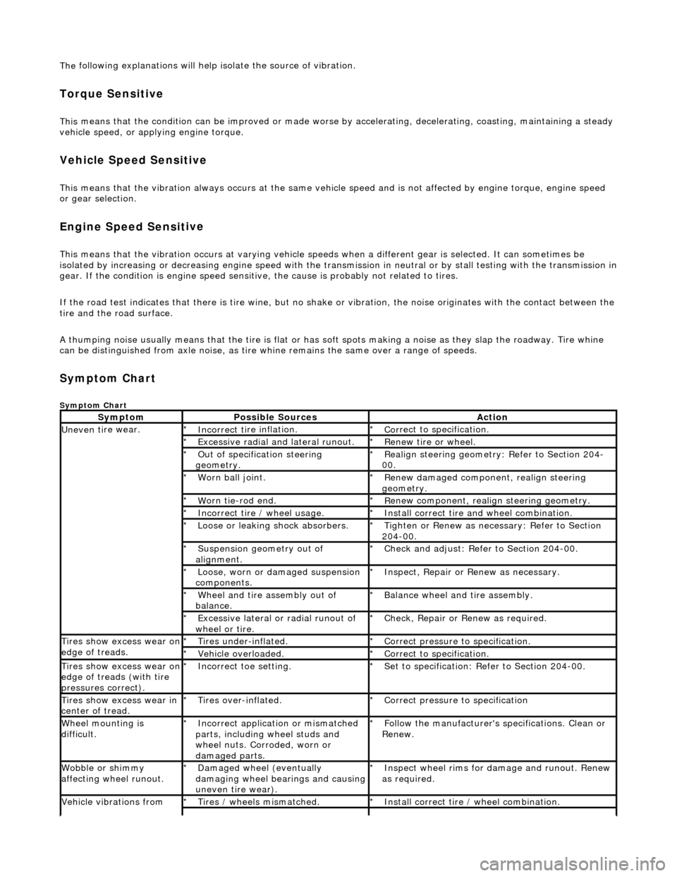
The
following explanations will help isolate the source of vibration.
Torque Sensitive
This
means that the condition can be impr
oved or made worse by accelerating, dece lerating, coasting, maintaining a steady
vehicle speed, or applying engine torque.
Ve
hicle Speed Sensitive
This means th
at the vibration al
ways occurs at the same vehicle speed and is not affected by engine torque, engine speed
or gear selection.
Engine Speed Sensit
ive
This means th
at the vibration
occurs at varying vehicle spee ds when a different gear is selected. It can sometimes be
isolated by increasing or decreasing engine speed with the tran smission in neutral or by stall testing with the transmission in
gear. If the condition is engine speed sensitive, the cause is probably not related to tires.
If the road test indicates that there is tire wine, but no shake or vibration, the noise originates with the contact between th e
tire and the road surface.
A thumping noise usually means that the tire is flat or has soft spots making a noise as they slap the roadway. Tire whine
can be distinguished from axle no ise, as tire whine remains the same over a range of speeds.
Sym
ptom Chart
Sy
mptom Chart
Sy
mptom
Possib
le Sources
Acti
on
Uneven ti
re wear.
Incorrect ti
re inflation.
*
Cor
rect to specification.
*
Exce
ssive radial an
d lateral runout.
*
Renew tire
or wheel.
*
O
ut of specification steering
geometry.
*
R
ealign steering geometry: Refer to Section 204-
00.
*
W
orn ball joint.
*
Renew
damaged component, realign steering
geometry.
*
W
orn tie-rod end.
*
R
enew component, realign steering geometry.
*
Incorrect
tire / wheel usage.
*
Inst
all correct tire and wheel combination.
*
Loose or leaki
ng shock absorbers.
*
Tigh
ten or Renew as nece
ssary: Refer to Section
204-00.
*
Suspensi
on geometry out of
alignment.
*
Che
ck and adjust: Refer to Section 204-00.
*
Loose, worn or da mage
d suspension
components.
*
In
spect, Repair or Renew as necessary.
*
Wh
eel and tire assembly out of
balance.
*
Balance wheel an
d tire assembly.
*
Excessive later
al or radial runout of
wheel or tire.
*
Check, Repair o
r
Renew as required.
*
Tire
s show excess wear on
edge of treads.
Ti
res under-inflated.
*
Cor
rect pressure to specification.
*
Vehi
cle overloaded.
*
Cor
rect to specification.
*
Tire
s show excess wear on
edge of treads (with tire
pressures correct).
Incorre
ct toe setting.
*
Se
t to specification: Refer to Section 204-00.
*
Tire
s show excess wear in
center of tread.
Tire
s over-inflated.
*
Cor
rect pressure to specification
*
W
heel mounting is
difficult.
Incorrect app
lication or mismatched
parts, including wheel studs and
wheel nuts. Corroded, worn or
damaged parts.
*
Fol
low the manufacturer's specifications. Clean or
Renew.
*
Wobble or sh
immy
affecting wheel runout.
Damaged wh
eel (eventually
damaging wheel bearings and causing
uneven tire wear).
*
Inspect wheel rims for
damage and runout. Renew
as required.
*
Vehicle vibrations from
Tire
s / wheels mismatched.
*
Inst
all correct tire / wheel combination.
*