handbrake JAGUAR X308 1998 2.G Workshop Manual
[x] Cancel search | Manufacturer: JAGUAR, Model Year: 1998, Model line: X308, Model: JAGUAR X308 1998 2.GPages: 2490, PDF Size: 69.81 MB
Page 222 of 2490
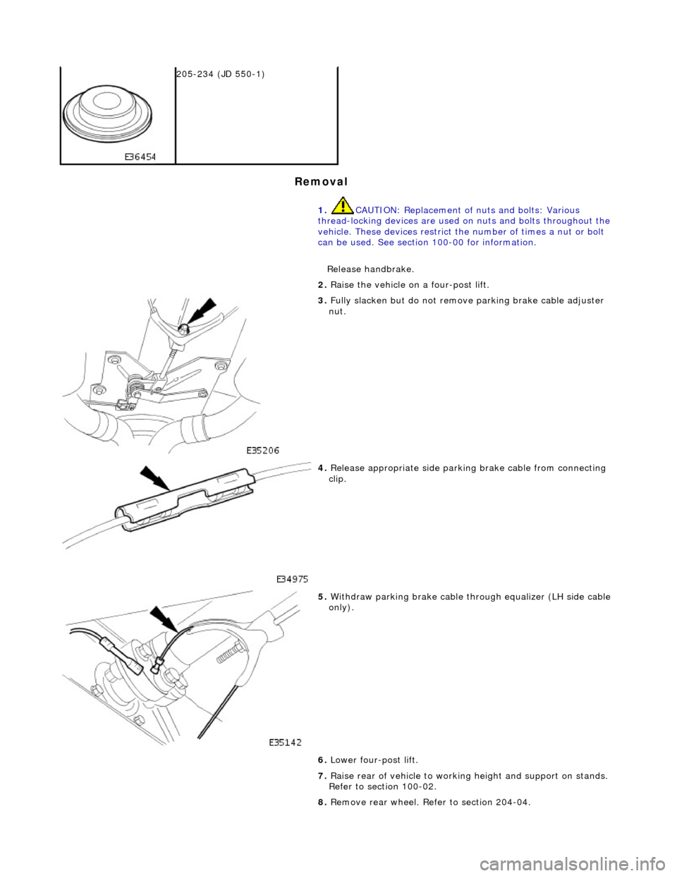
Remova
l
2
05-2
34 (JD 550-1)
1. CAUTION: Replacement of nuts and bolts: Various
thread-locking devices are used on nuts and bolts throughout the
vehicle. These devices restrict the number of times a nut or bolt
can be used. See section 100-00 for information.
Release handbrake.
2. Ra
ise the vehicle on a four-post lift.
3. Fully slacken bu
t do not remove parking brake cable adjuster
nut.
4. Relea s
e appropriate side parkin
g brake cable from connecting
clip.
5. With draw parkin
g brake cable th
rough equalizer (LH side cable
only).
6. Lower four-post lift.
7. Raise rear of vehicle to workin g height and support on stands.
Refer to section 100-02.
8. Remove rear wheel. Refer to section 204-04.
Page 226 of 2490
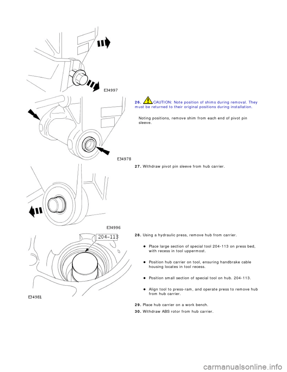
26. CAUTI
ON: Note position of
shims during removal. They
must be returned to their original positions during installation.
Noting positions, remove shim from each end of pivot pin
sleeve.
27 . W
ithdraw pivot pin sleeve from hub carrier.
28 .
Using a h
ydraulic press,
remove hub from carrier.
Plac
e large section of special tool 204-113 on press bed,
with recess in t ool uppermost.
Positi
on hub carrier on tool
, ensuring handbrake cable
housing locates in tool recess.
Posit i
on small section of special tool on hub. 204-113.
Align to
ol to press-r
am, and
operate press to remove hub
from hub carrier.
29. Place hub carrier on a work bench.
30. Withdraw ABS rotor from hub carrier.
Page 234 of 2490

29. Tigh
ten pivot pin nut.
Al
ign mark
er on pivot pin flange with mark made on
wishbone.
Ensuri ng pi
n position is not
disturbed, tighten nut to 88-
118Nm.
30 . Inst
all wheel speed sensor on hub carrier.
Posit
i
on sensor on hub carrier
and install and tighten bolt
to 7-10Nm.
Connect
wheel speed sensor harness to sensor.
31 . Using new ti
e strap, secure wh
eel speed sensor harness to
hub carrier.
32. Install handbrake shoes. Re fer to operation 70.40.05.
33. Install brake disc. Refer to operation 70.10.13.
34. Position special tool 204-195 on hub studs and install
securing nuts.
Page 242 of 2490
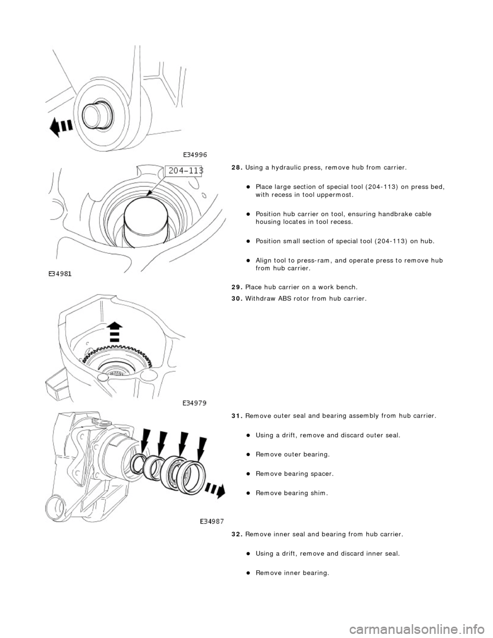
28. Using a h
ydraulic press,
remove hub from carrier.
Pla
ce large section of special tool (204-113) on press bed,
with recess in t ool uppermost.
Positi
on hub carrier on tool
, ensuring handbrake cable
housing locates in tool recess.
P o
sition small section of spec
ial tool (204-113) on hub.
Align tool to press-r
am, and
operate press to remove hub
from hub carrier.
29. Place hub carrier on a work bench.
30 . W
ithdraw ABS rotor from hub carrier.
31 . Remove ou
ter seal and bearin
g assembly from hub carrier.
Using a drift, re
move an
d discard outer seal.
Remove ou ter bearin
g.
Re
mo
ve bearin
g spacer.
Remove bearin g shim.
32
.
Remove inner seal and bearing from hub carrier.
Using a drift, re
move and discard inner seal.
Re
move inner bearing.
Page 246 of 2490

14. Inst
all wheel speed sensor on hub carrier.
Posit
i
on sensor on hub carrier
and install and tighten bolt
to 7-10Nm.
Conne ct
wheel speed sensor harness to sensor.
15 . Using new ti
e strap, secure wh
eel speed sensor harness to
hub carrier.
16. Install handbrake shoes. Re fer to operation 70.40.05.
17. Install brake disc. Refer to operation 70.10.13.
18 . Posit
ion special tool (204-195)
on hub studs and install nuts.
19. Tighten hub nut to 304-336Nm.
Page 251 of 2490
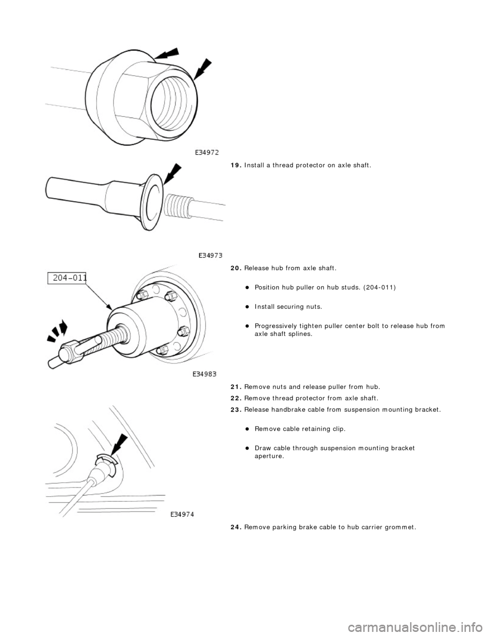
19
.
Install a thread protector on axle shaft.
20
.
Release hub from axle shaft.
Position hu
b puller on hub studs. (204-011)
Inst
all securing nuts.
Progres
sively tighten
puller center bolt to release hub from
axle shaft splines.
21. Remove nuts and release puller from hub.
22. Remove thread protec tor from axle shaft.
23
.
Release handbrake cable from suspension mounting bracket.
Remove cable reta
ining clip.
Draw c
able through suspension mounting bracket
aperture.
24. Remove parking brake cable to hub carrier grommet.
Page 397 of 2490

I
nstallation
Re
move bolts.
R
emove lever.
10
.
Remove gasket.
11
.
Remove warning-light switch from lever.
R
emove screws.
Re
move switch.
1. Inst
all warning-light switch to hand lever.
Install and tigh
ten
screws to 3 Nm.
2. Install gasket to handbrake lever.
Page 399 of 2490
Parking Brake and Act
uation - Parking Brake Control Shroud
Re
moval and Installation
Remov
al
Installation
1.
Position ha
ndbrake lever fully up.
2. Remove trim from handbrake lever.
1. Release press stud at to p of handbrake lever trim.
2. Ease lower moulding away from boss at base of lever and slide trim upwards.
1. Slide trim over handbrake lever and position lower moulding
over boss.
2. Fasten press stud at top of trim.
3. Check that 'J' gate selector is in position P.
4. Lower handbrake lever, checki ng for freedom of movement.
5. Pull handbrake lever fully up.
Page 896 of 2490
Engine - Engine
Removal
Removal
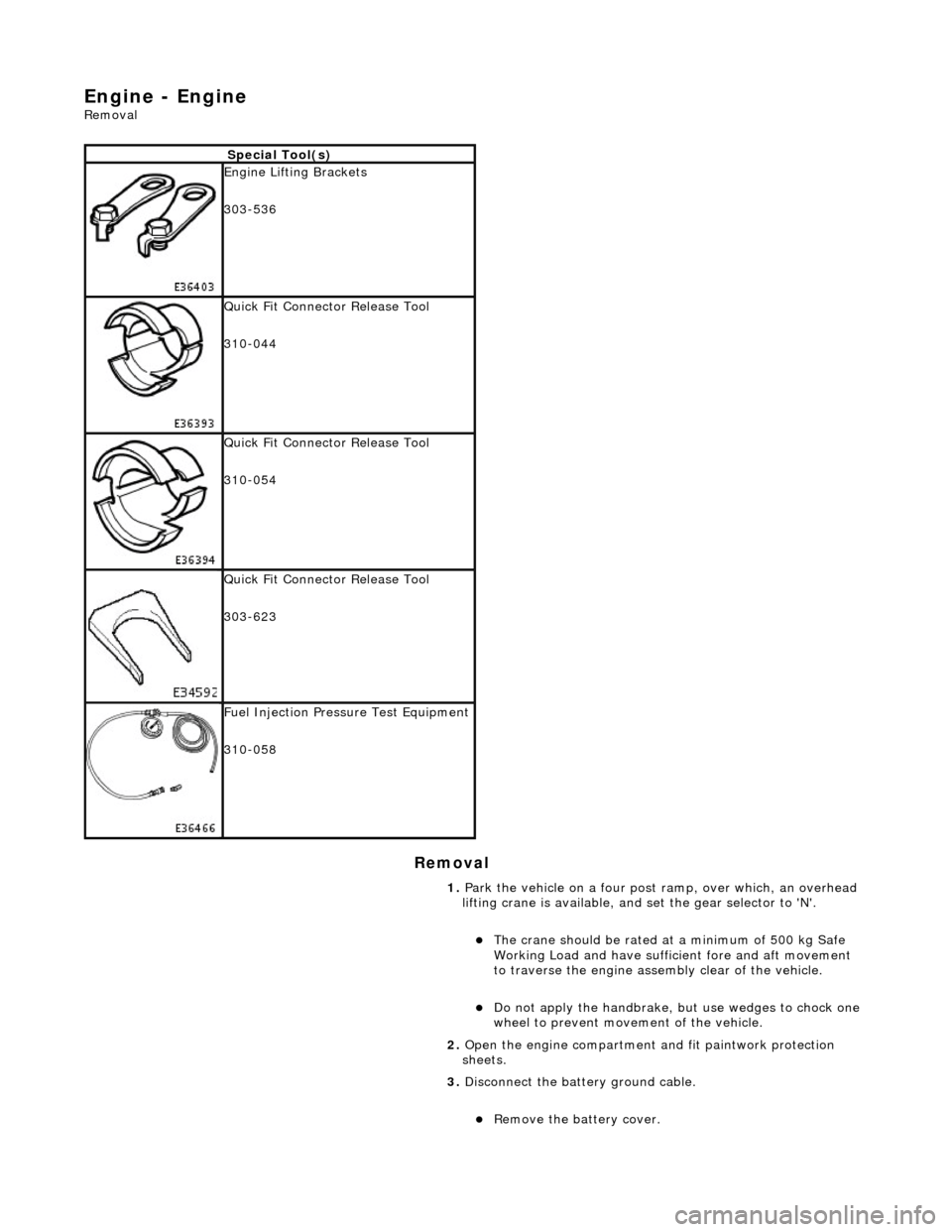
Special Tool(s)
Engine Lifting Brackets
303-536
Quick Fit Connector Release Tool
310-044
Quick Fit Connector Release Tool
310-054
Quick Fit Connector Release Tool
303-623
Fuel Injection Pressure Test Equipment
310-058
1. Park the vehicle on a four post ramp, over which, an overhead
lifting crane is available, and set the gear selector to 'N'.
The crane should be rated at a minimum of 500 kg Safe
Working Load and have suffici ent fore and aft movement
to traverse the engine assemb ly clear of the vehicle.
Do not apply the handbrake, but use wedges to chock one
wheel to prevent movement of the vehicle.
2. Open the engine compartment and fit paintwork protection
sheets.
3. Disconnect the batt ery ground cable.
Remove the battery cover.
Page 1855 of 2490
The In
strument Cluster is the primary electronic control module for the speedomete
r, tachometer, coolant temperature, fuel
level, driver information (Message Centre) and warning lamps.
The Instrument Cluster also:
- provides input / output informatio n signals for use by other modules.
- acts as a protocol converter (software language translator - the languages used on each network are very similar, but
neither can be directly interp reted by the opposite system) for communication between all modules on both the CAN and
SCP multiplexed networks. The Instrument Cluster is the only module on the vehicle which communicates between the two
networks.
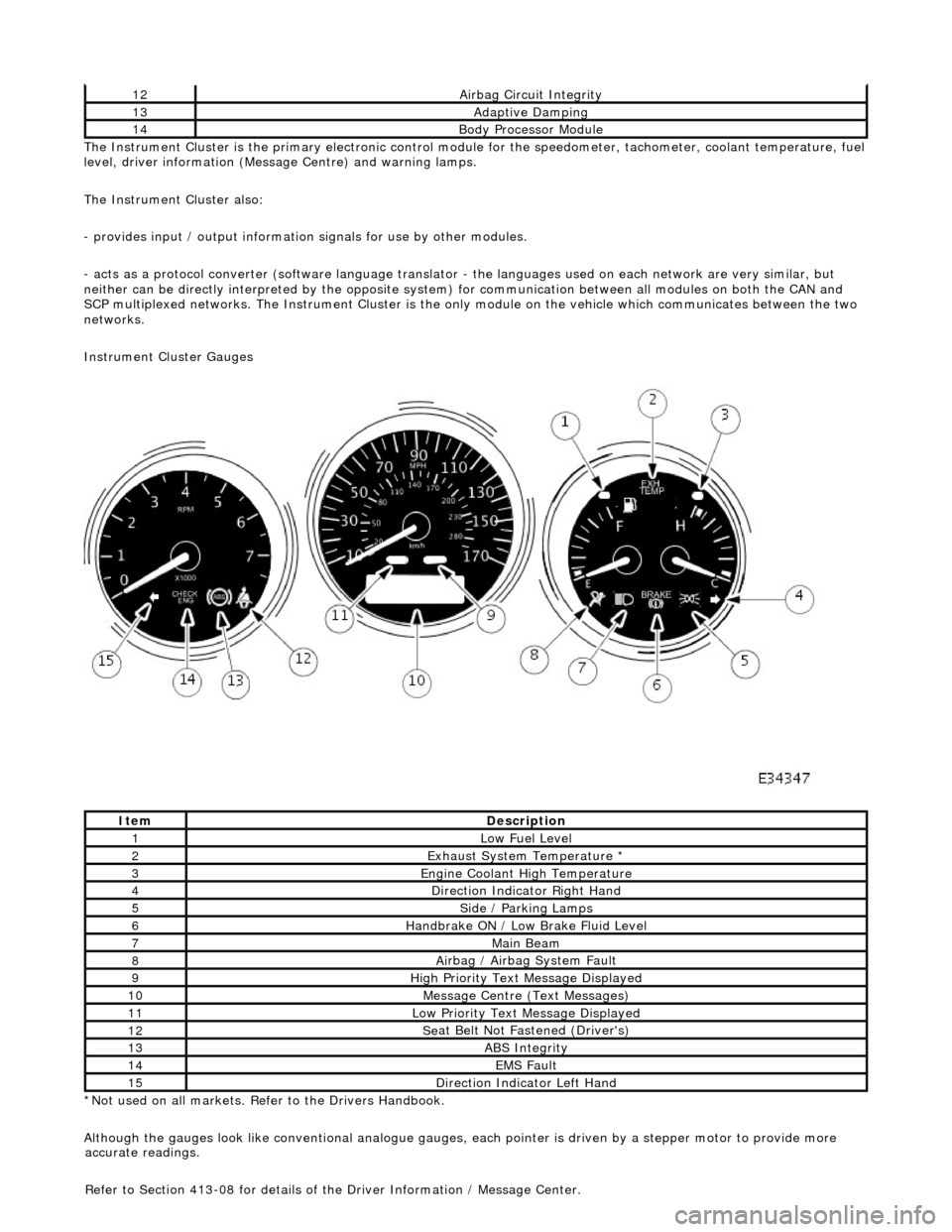
Instrument Cluster Gauges
*Not used on all markets. Refer to the Drivers Handbook.
Although the gauges look like conventional analogue gauges, each pointer is driven by a stepper motor to provide more
12Ai
rbag Circuit Integrity
13Adaptive Damping
14Body Processor
Module
It
em
De
scription
1Low Fu
el Level
2Exhaus
t System Temperature *
3E
ngine Coolant High Temperature
4Di
rection Indicator Right Hand
5Side
/ Parking Lamps
6Handbrake ON / Low
Bra
ke Fluid Level
7Main
Beam
8Ai
rbag / Airbag System Fault
9Hi
gh Priority Text
Message Displayed
10M
essage Centre (Text Messages)
11Low Pri
ority Text Message Displayed
12Se
at Belt Not Fa
stened (Driver's)
13ABS Integrity
14EMS Fault
15D
irection Indicator Left Hand
accu
rate readings.
Refer to Section 413-08 for details of the Driver Information / Message Center.