heating JAGUAR X308 1998 2.G Workshop Manual
[x] Cancel search | Manufacturer: JAGUAR, Model Year: 1998, Model line: X308, Model: JAGUAR X308 1998 2.GPages: 2490, PDF Size: 69.81 MB
Page 21 of 2490

В В В В В В В В В В В В В В В В В В В В AirВ Distributio nВ and В Filt
ering
В
В В В В В В В В В В В В В В В В Diagnosis В and В Testing В
В В В В В В В В В В В В В В В В В В В В AirВ Distribution В and В Filtering В
В В В В В В В В В В В В В В В В RemovalВ and В Installation В
В В В В В В В В В В В В В В В В В В В В CenterВ Registers В (82.20.38) В
В В В В В В В В В В В В В В В В В В В В DriverВ Side В Blower В Motor В (82.25.56) В
В В В В В В В В В В В В В В В В В В В В PassengerВ Side В Blower В Motor В (82.25.55) В
В В В В В В В В В В В В В В В В В В В В PlenumВ Chamber В (82.20.87) В
В
В В В В В В В В В В В В 412‐02: В Heating В and В Ventilation В
В В В В В В В В В В В В В В В В Description В and В Operation В
В В В В В В В В В В В В В В В В В В В В HeatingВ and В Ventilation В
В В В В В В В В В В В В В В В В В В В
В В В В В В В В В В В В В В В В В В В В В
В В
В В В В В В В В В В В В В В В В Removal
В and В Installation В
В В В В В В В В В В В В В В В В В В В В Heater
В Core В (80.20.29) В
В В В В В В В В В В В В В В В В В В В В Heater
В Core В and В Evaporator В Core В Housing В (82.25.21) В
В
В В В В В В В В В В В В 412
‐03: В Air В Conditioning В
В В В В В В В В В В В В В В В В Description
В and В Operation В
В В В В В В В В В В В В В В В В В В В В AirВ
Conditioning В
В В В В В В В В В В В В В В В В Diagnosis
В and В Testing В
В В В В В В В В В В В В В В В В В В В В AirВ
Conditioning В
В В В В В В В В В В В В В В В В Removal
В and В Installation В
В В В В В В В В В В В В В В В В В В В В AirВ
Conditioning В (A/C) В CompressorВ (82.10.20)В
В В В В В В В В В В В В В В В В В В В В Condenser
В Core В (82.15.07) В
В В В В В В В В В В В В В В В В В В В В Evaporator
В Core В (82.25.20) В
В В В В В В В В В В В В В В В В В В В В Press
ureВ Cutoff В Switch В (82.10.32) В
В В В В В В В В В В В В В В В В В В В В Receiver
В Drier В (82.17.01) В
В
В В В В В В В В В В В В 412
‐04: В Control В Components В
В В В В В В В В В В В В В В В В Description
В and В Operation В
В В В В В В В В В В В В В В В В В В В В ControlВ
Components В
В В В В В В В В В В В В В В В В Diagnosis
В and В Testing В
В В В В В В В В В В В В В В В В В В В В ControlВ
Components В
В В В В В В В В В В В В В В В В Removal
В and В Installation В
В В В В В В В В В В В В В В В В В В В В AirВ
Discharge В Temperature В Sensor В (82.20.64) В
Page 42 of 2490
General Information - Terminology Glossary
Description an
d Operation
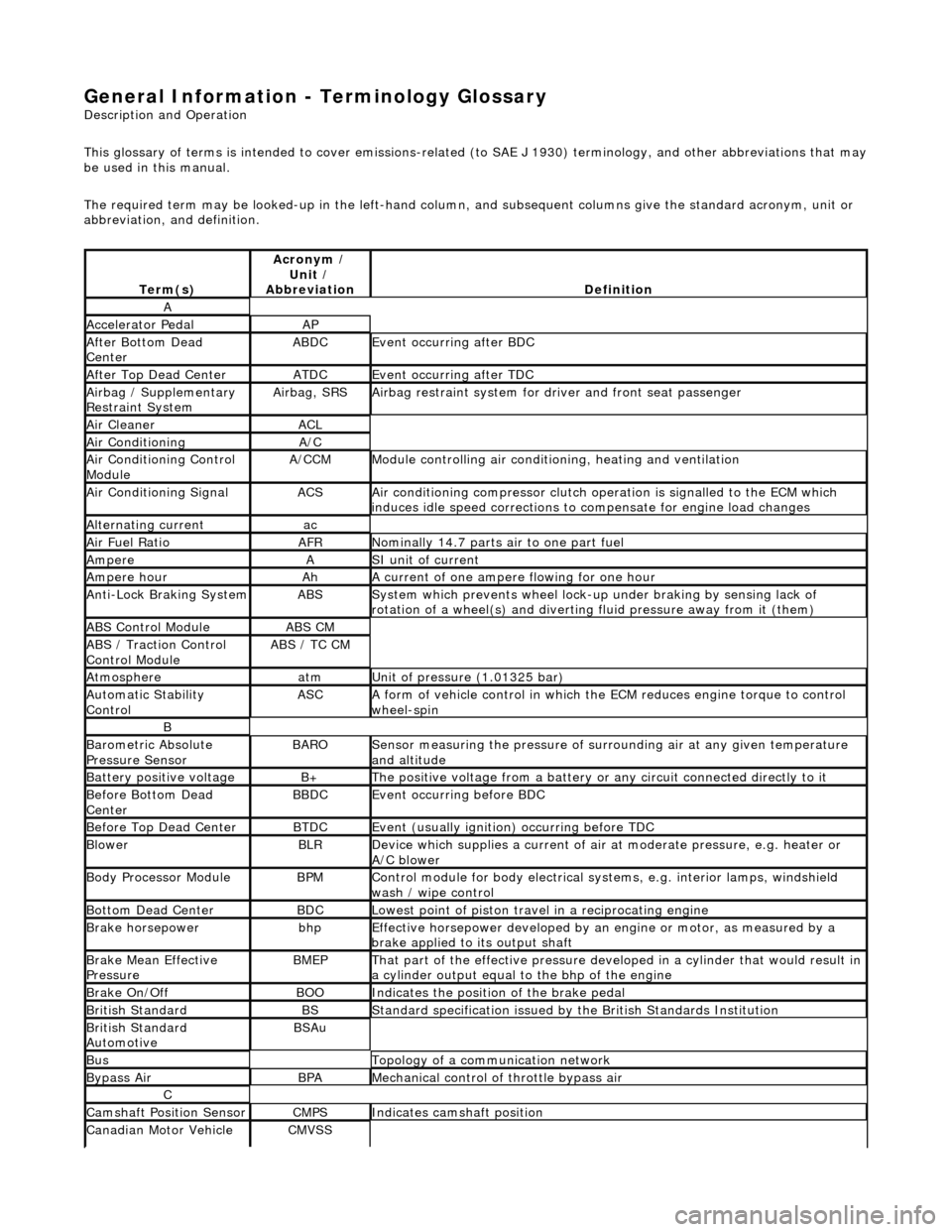
This glossary of terms is intended to cover emissions-related (to SAE J 1930) term inology, and other abbreviations that may
be used in this manual.
The required term may be looked-up in th e left-hand column, and subsequent columns give the standard acronym, unit or
abbreviation, and definition.
Te rm
(s)
Acr
ony
m /
Unit /
Abbreviation
De fi
nition
A
Accel
e
rator Pedal
AP
Af
ter Botto
m Dead
Center
ABDCEvent occurri ng after
BDC
Af
ter Top Dead CenterATDCEvent occurri ng after
TDC
Ai
rbag /
Supplementary
Restraint System
Airbag, SRSAi rbag restraint system for
dr
iver and front seat passenger
Air Cleane rACL
Air ConditioningA/C
Air Conditioning Con t
rol
Module
A/CCMModule c
ontrolling air conditioning, heating and ventilation
Air Conditioning SignalACSA
i
r conditioning compressor clutch operation is signalled to the ECM which
induces idle speed corrections to co mpensate for engine load changes
Alternating cu
rrent
ac
Ai
r Fuel R
atio
AFRN
omi
nally 14.7 parts air to one part fuel
Ampe
reASI unit of current
Ampere hourAhA current of one ampere
fl
owing for one hour
Anti-Lock Braking SystemABSS
y
stem which prevents wheel lock-up
under braking by sensing lack of
rotation of a wheel(s) and divertin g fluid pressure away from it (them)
ABS Control Mo
dule
ABS CM
ABS /
T
raction Control
Control Module
ABS / T
C CM
Atmosph
e
re
atmU
n
it of pressure (1.01325 bar)
Au
to
matic Stability
Control
ASCA form of vehicle
control
in which the ECM reduces en gine torque to control
wheel-spin
B
Baro me
tric Absolute
Pressure Sensor
BAR OSensor measuring the pressure of surr ou
nding air at any given temperature
and altitude
Bat t
ery positive voltage
B+The posi
ti
ve voltage from a battery or
any circuit connected directly to it
Before Bottom Dead
CenterBBDCEvent occurri ng before BD
C
Before Top Dead
Center
BTD
CEvent (usual ly
ignition) occurring before TDC
Blowe
rBLRDe
vice which supplies a current of air at
moderate pressure, e.g. heater or
A/C blower
Body Processor M
odule
BPMControl modu
le
for body electrical systems, e.g. interior lamps, windshield
wash / wipe control
Bott om D
ead Center
BD
CLowest poin t of piston
travel in a reciprocating engine
Brake hors
epowe
r
bhpEffecti
ve horsepower devel
oped by an
engine or motor, as measured by a
brake applied to its output shaft
Brake Mean Effective
Pres sureBME PThat p
art of the effective
pressure developed in a cyli nder that would result in
a cylinder output equal to the bhp of the engine
Brake On/ O
ff
BOOIn
dic
ates the position of the brake pedal
Br
it
ish Standard
BSStan
dar
d specification issued by the British Standards Institution
Br
it
ish Standard
Automotive
BSAu
BusTopology of a commu n
ication network
Bypass
AirBPAMechanica l
control of throttle bypass air
C
Camshaft Posit
i
on Sensor
CMPSIndi
cat
es camshaft position
Canadian Motor
V
ehicle
CMVSS
Page 458 of 2490
The
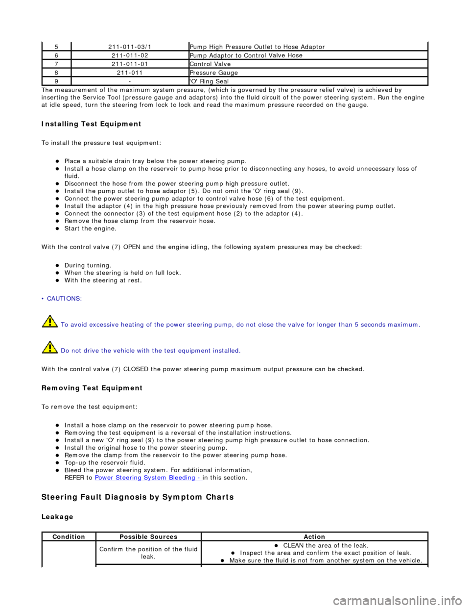
measurement of the maximum system pressure, (which is
governed by the pressure relief valve) is achieved by
inserting the Service Tool (pressure gauge and adaptors) into th e fluid circuit of the power steering system. Run the engine
at idle speed, turn the st eering from lock to lock and read the ma ximum pressure recorded on the gauge.
Installin
g Test Equipment
To
in
stall the pressure test equipment:
пЃ¬Pla
c
e a suitable drain tray be
low the power steering pump.
пЃ¬Install a hose clamp on
the re
servoir to pump hose prior to disconnecting any hoses, to avoid unnecessary loss of
fluid.
пЃ¬Disc
onnect the hose from the power st
eering pump high pressure outlet.
пЃ¬Install the pu
mp outlet to hose adaptor (5
). Do not omit the 'O' ring seal (9).
пЃ¬Connect the power steering
pump
adaptor to control valve hose (6) of the test equipment.
пЃ¬Install th e adaptor (4) in th
e high
pressure hose previously removed from the power steering pump outlet.
пЃ¬Conn
ect the connector (3) of the test equipment hose (2) to the adaptor (4).
пЃ¬R
e
move the hose clamp fro
m the reservoir hose.
пЃ¬Start th
e engine.
With the control valve (7) OPEN and the engine idli ng, the following system pressures may be checked:
пЃ¬Du
ring turning.
пЃ¬W
h
en the steering is
held on full lock.
пЃ¬With
the steeri
ng at rest.
• CAUTIONS:
To avoid excessive heating of the po wer steering pump, do not close the valve for longer than 5 seconds maximum.
Do not drive the vehicle with the test equipment installed.
With the control valve (7) CLOSED the power steering pump maximum ou tput pressure can be checked.
Removing Test Equipment
To
remove the test equipment:
пЃ¬Install a hose clamp
on
the reservoir to power steering pump hose.
пЃ¬Re
movi
ng the test equipmen
t is a reversal of the in stallation instructions.
пЃ¬Install a new '
O
' ring seal (9) to the power steering pump high pressu
re outlet to hose connection.
пЃ¬Instal
l the original hose to
the power steering pump.
пЃ¬Re
move the clamp from the reservoir to
the power steering pump hose.
пЃ¬Top-up the reservoir flui
d.
пЃ¬Ble
e
d the power steerin
g system. For additional information,
REFER to Power Steering System Bleeding
- in thi
s section.
Stee
ring Fault Diagnosis by Sympt
om Charts
Leakage
52
11-0
11-03/1
Pump High Pressure Ou
tlet
to Hose Adaptor
621
1
-011-02
Pump Adaptor
to Contro
l Valve Hose
721
1
-011-01
Control Valve
82
11-
011
Pressure Gauge
9-'O
'
Ring Seal
Cond
iti
on
Possib
l
e Sources
Acti
o
n
Co
nfirm
the position of the fluid
leak.
пЃ¬CLEAN th
e area of the leak.
пЃ¬In
s
pect the area and confirm the exact position of leak.
пЃ¬Make sure the fluid
is not from anoth
er system on
the vehicle.
Page 490 of 2490
Power Steering - Power Steering
Diagn
osis and Testing
Refer to the Description and Operation sub-section for details of the power operated steering system and Servotronic control
system.
Power Steer ing Pressure Test
Test Equ
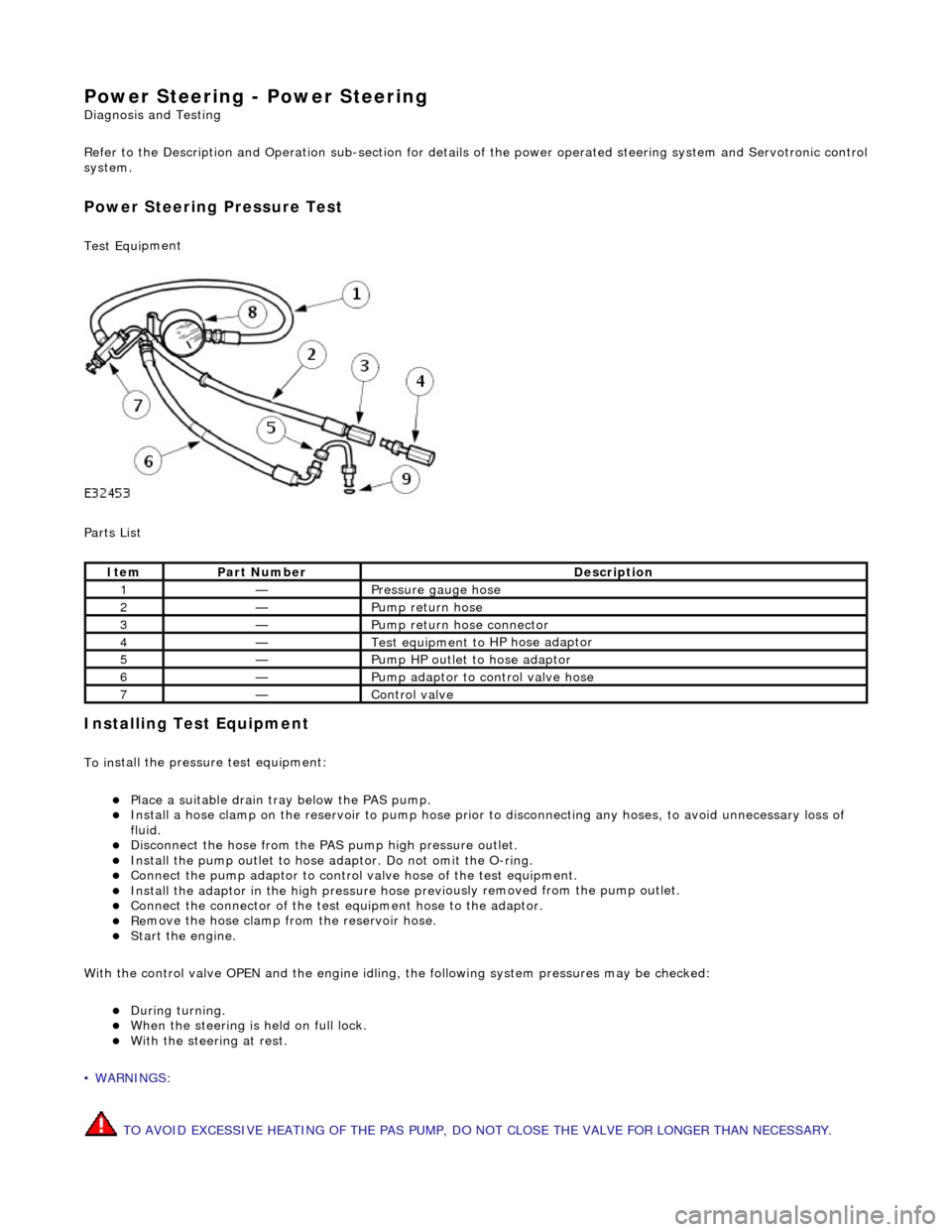
i
pment
Parts List
In
stalling Test Equipment
To
in
stall the pressure test equipment:
пЃ¬Pla
c
e a suitable drain tray below the PAS pump.
пЃ¬Install a hose clamp
on
the re
servoir to pump hose prior to disconnecting any hoses, to avoid unnecessary loss of
fluid.
пЃ¬Di sc
onnect the hose from the PAS pump high pres
sure outlet.
пЃ¬Ins
tall the pump outlet to hose ad
aptor. Do not omit the O-ring.
пЃ¬Conn
ect the pump adaptor to control valve hose of the test equipment.
пЃ¬Install th
e adaptor in the high pressure hose previ
ously re
moved from the pump outlet.
пЃ¬Conne
ct the connector of the test equipment hose to the adaptor.
пЃ¬R
e
move the hose clamp fro
m the reservoir hose.
пЃ¬Start th
e engine.
With the control valve OPEN and the engine idling , the following system pressures may be checked:
пЃ¬Du
ring turning.
пЃ¬W
h
en the steering is
held on full lock.
пЃ¬With
the steeri
ng at rest.
• WARNINGS:
TO AVOID EXCESSIVE HEATING OF THE PAS PUMP, DO NOT CLOSE THE VALVE FOR LONGER THAN NECESSARY.
Ite
m
Par
t
Number
De
scr
iption
1—Pressure
gauge hose
2—Pump return hose
3—Pump return hose connector
4—Test equi
pment to
HP hose adaptor
5—Pump HP outlet to hose adaptor
6—Pump adaptor
to control valve hose
7—Control valve
Page 1179 of 2490
пЃ¬generates a signal when th
e dr
ive plate passes the sensor
пЃ¬sen
ds the ECM signals indicating crankshaft position and engine speed
пЃ¬is e
ssential for calculating spark timing
En
gine Coolant Temperature (ECT) Sensor
пЃ¬sen
ds the ECM a signal indicating the temperature of the engine coolant
пЃ¬is a t
emperature dependent resistor with a negative temperature coefficient (resistance changes inversely with
respect to temperature) and is constantly monitored by the ECM
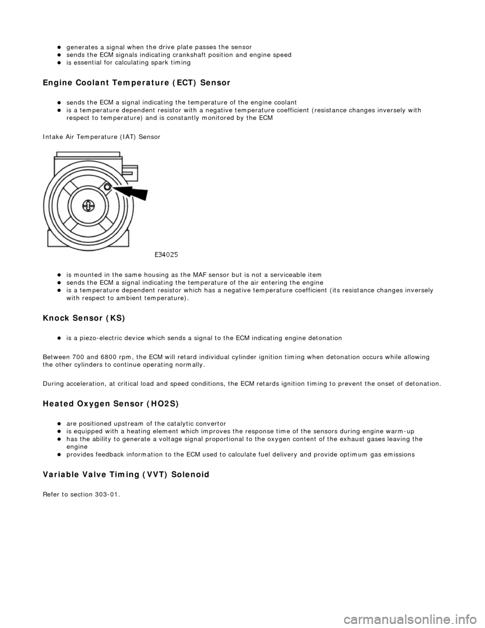
Intake Air Temperature (IAT) Sensor
пЃ¬is m
ounted in the same housing as the MA
F sensor but is not a serviceable item
пЃ¬sen
ds the ECM a signal indicating the temperature of the air entering the engine
пЃ¬is a t
emperature dependent resistor which has a negative
temperature coefficient (its resistance changes inversely
with respect to ambient temperature).
Knock S
ensor (KS)
пЃ¬is a pi
ezo-electric device which sends a signal
to the ECM indicating engine detonation
Between 700 and 6800 rpm, the ECM will retard individual cylinder ignition timing when detonation occurs while allowing
the other cylinders to continue operating normally.
During acceleration, at critical load and speed conditions, the ECM retards ignition timing to prevent the onset of detonation.
H
eated Oxygen Sensor (HO2S)
пЃ¬are
positioned upstream of the catalytic convertor
пЃ¬is equipped with
a heating element wh
ich improves the response time of the sensors during engine warm-up
пЃ¬h
as the ability to generate a voltage signal proportional to the oxygen content of the exhaust gases leaving the
engine
пЃ¬pr
ovides feedback information to the ECM used to calc
ulate fuel delivery and provide optimum gas emissions
Variable V
alve Timing (VVT) Solenoid
R
efer to section 303-01.
Page 1195 of 2490
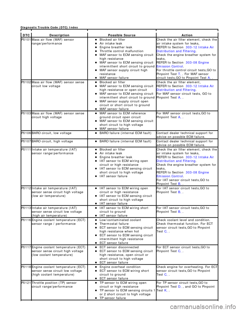
DT
C
De
scription
Possib
le Source
Acti
on
P0101Mass ai
r flow (MAF) sensor
range/performance
пЃ¬Bl
ocked air filter
пЃ¬Air
intake leak
пЃ¬Engine
breather leak
пЃ¬Throttl
e control malfunction
пЃ¬MAF
sensor to ECM sensing circuit
high resistance
пЃ¬MAF
sensor to ECM sensing circuit
intermittent short circuit to ground
пЃ¬MAF
sensor supply circuit high
resistance
пЃ¬MAF
sensor failure
Chec
k the air filter element, check the
air intake system for leaks,
REFER to Section 303
-1
2 Intake Air
Distribu
tion and Filtering
.
Chec
k the engine breather system for
leaks,
REFER to Section 303
-08
Engine
Emissi
on Control
.
F
or throttle control circuit tests,GO to
Pinpoint Test T.
. Fo
r MAF sensor
circuit tests,GO to Pinpoint Test A.
.
P0102Mass ai
r flow (MAF) sensor sense
circuit low voltage
пЃ¬Bl
ocked air filter
пЃ¬MAF
sensor to ECM sensing circuit
high resistance or open circuit
пЃ¬MAF
sensor to ECM sensing circuit
intermittent short circuit to ground
пЃ¬MAF
sensor supply circuit open
circuit or short circuit to ground
пЃ¬MAF
sensor failure
Chec
k the air filter element,
REFER to Section 303
-1
2 Intake Air
Distribu
tion and Filtering
.
For MAF
sensor circuit tests, GO to
Pinpoint Test A.
.
P0103Mass ai
r flow (MAF) sensor sense
circuit high voltage
пЃ¬MAF
sensor to ECM reference
ground circuit open circuit
пЃ¬MAF
sensor to ECM sensing circuit
short circuit to high voltage
пЃ¬MAF sensor
failure
For MAF
sensor circuit tests,GO to
Pinpoint Test A.
.
P0106BARO ci
rcuit, low voltage
пЃ¬BARO f
ailure (internal ECM fault)
Contact deal
er technical support for
advice on possible ECM failure.
P0107BARO ci
rcuit, high voltage
пЃ¬BARO f
ailure (internal ECM fault)
Contact deal
er technical support for
advice on possible ECM failure.
P0111In
take air temperature (IAT)
sensor range/performance
пЃ¬Bl
ocked air filter
пЃ¬Air
intake leak
пЃ¬Engine
breather leak
пЃ¬IAT sensor to
ECM wiring open
circuit or high resistance
пЃ¬IAT se
nsor to ECM sensing circuit
short circuit to high voltage
пЃ¬IAT sensor fail
ure
Chec
k the air filter element, check the
air intake system for leaks,
REFER to Section 303
-1
2 Intake Air
Distribu
tion and Filtering
.
Chec
k the engine breather system for
leaks,
REFER to Section 303
-08
Engine
Emissi
on Control
.
F
or IAT sensor circuit tests,GO to
Pinpoint Test B.
.
P0112In
take air temperature (IAT)
sensor sense circuit high voltage
(low air temperature)
пЃ¬IAT sensor to
ECM wiring open
circuit or high resistance
пЃ¬IAT se
nsor to ECM sensing circuit
short circuit to high voltage
пЃ¬IAT sensor fail
ure
F
or IAT sensor circuit tests,GO to
Pinpoint Test B.
.
P0113In
take air temperature (IAT)
sensor sense circuit low voltage
(high air temperature)
пЃ¬IAT sensor to
ECM wiring short
circuit to ground
пЃ¬IAT sensor fail
ure
F
or IAT sensor circuit tests,GO to
Pinpoint Test B.
.
P0116E
ngine coolant temperature (ECT)
sensor range / performance
пЃ¬Low/contaminated coolant пЃ¬Therm
ostat failure
пЃ¬ECT se
nsor to ECM sensing circuit
high resistance when hot
пЃ¬ECT se
nsor to ECM sensing circuit
intermittent high resistance
пЃ¬ECT sensor
failure
Che
ck coolant level and condition.
Check thermostat function. For ECT
sensor circuit tests,GO to Pinpoint
Test C.
.
P0117E
ngine coolant temperature (ECT)
sensor sense circuit high voltage
(low coolant temperature)
пЃ¬ECT se
nsor disconnected
пЃ¬ECT se
nsor to ECM sensing circuit
high resistance, open circuit or
short circuit to high voltage
пЃ¬ECT sensor
failure
F
or ECT sensor circuit tests,GO to
Pinpoint Test C.
.
P0118E
ngine coolant temperature (ECT)
sensor sense circuit low voltage
(high coolant temperature)
пЃ¬Engine
overheat condition
пЃ¬ECT se
nsor to ECM wiring short
circuit to ground
пЃ¬ECT sensor
failure
Chec
k engine for overheating. For ECT
sensor circuit tests,GO to Pinpoint
Test C.
.
P0121Thro
ttle position (TP) sensor
circuit rang e/performance
пЃ¬TP sensor
to ECM wiring open
circuit or high resistance
пЃ¬TP se
nsor to ECM sensing circuits 1
or 2 short circuit to high voltage
пЃ¬TP sensor
failure
F
or TP sensor circ
uit tests,GO to
Pinpoint Test D.
, and G
O to Pinpoint
Test K.
.
D
iagnostic Trouble Code (DTC) Index
Page 1462 of 2490
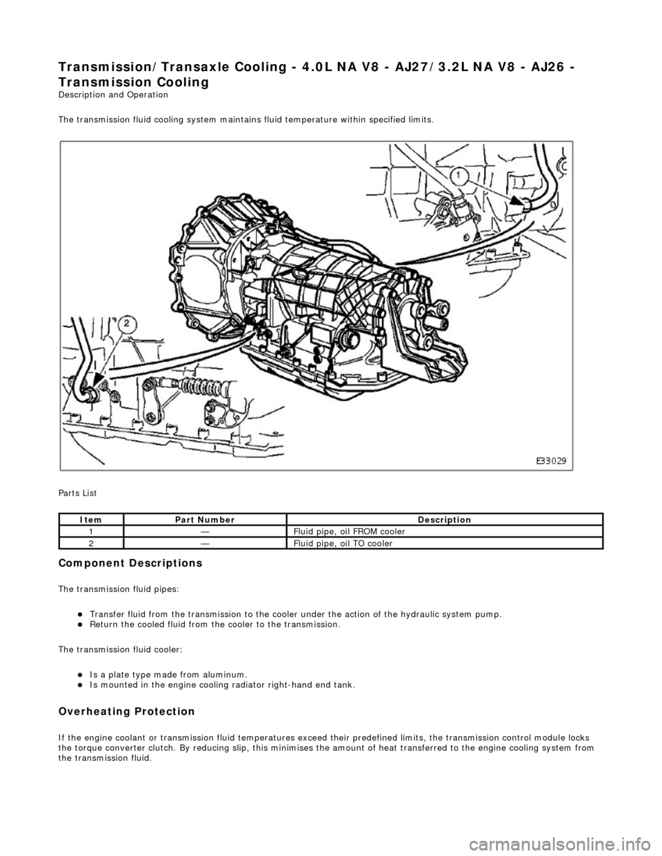
Transmission/Transaxle Cooling - 4.0L NA V8 - AJ27/3.2L NA V8 - AJ26 -
Transmission Cooling
Description and Operation
The transmission fluid cooling system maintains fluid temperature within specified limits.
Parts List
Component Descriptions
The transmission fluid pipes:
пЃ¬Transfer fluid from the transmission to the cooler under the action of the hydraulic system pump. пЃ¬Return the cooled fluid from th e cooler to the transmission.
The transmission fluid cooler:
пЃ¬Is a plate type made from aluminum. пЃ¬Is mounted in the engi ne cooling radiator right-hand end tank.
Overheating Protection
If the engine coolant or transm ission fluid temperatures exceed their predefined limits, th e transmission control module locks
the torque converter clutch. By reducing slip, this minimises th e amount of heat transferred to the engine cooling system from
the transmission fluid.
ItemPart NumberDescription
1—Fluid pipe, oil FROM cooler
2—Fluid pipe, oil TO cooler
Page 1463 of 2490
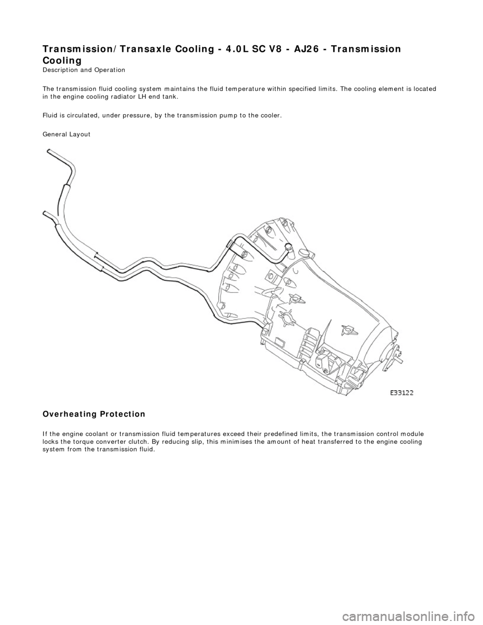
Transmission/Transaxle Cooling - 4.0L SC V8 - AJ26 - Transmission
Cooling
Description and Operation
The transmission fluid cooling system maintains the fluid temperature within specified limits. The cooling element is located
in the engine cooling radiator LH end tank.
Fluid is circulated, under pressure, by the transmission pump to the cooler.
General Layout
Overheating Protection
If the engine coolant or transmission fluid temperatures exceed their predefined limits, the transmission control module
locks the torque converter clutch . By reducing slip, this minimises the amount of heat transferred to the engine cooling
system from the transmission fluid.
Page 1760 of 2490
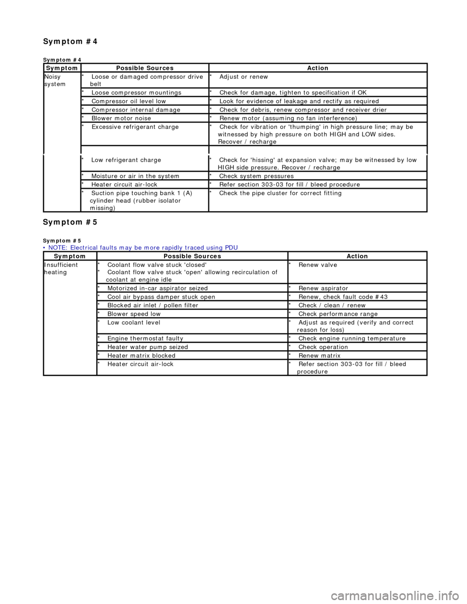
Symp
tom #5
Sy
m
ptom #5
Low r
e
frigerant charge
*
Check f or 'hissi
ng' at expansion
valve; may be witnessed by low
HIGH side pressure. Recover / recharge
*
Moi
s
ture or air in the system
*
Chec k syst
em pressures
*
Heat er ci
rcuit air-lock
*
R e
fer section 303-03 for fill / bleed procedure
*
Suct ion
pipe touching bank 1 (A)
cylinder head (rubber isolator
missing)
*
Check the pi
pe cluster for correct fitti
ng
*
• NOTE: Electrical faults may be more rapidly traced using PDU
Sym
ptom
Possib
l
e Sources
Acti
o
n
Insuffi
ci
ent
heating
Coo l
ant flow valve stuck 'closed'
Coolant flow valve stuck 'open' allowing recirculation of
coolant at engine idle
*
*
Re
new v
alve
*
Motorized in-car aspirator sei zed
*R e
new aspirator
*
Coo l
air bypass damper stuck open
*
Re new,
check fault code #43
*
B l
ocked air inlet / pollen filter
*
Chec k / cl
ean / renew
*
B l
ower speed low
*
Check performance range
*
Low cool ant
level
*
Adjust as req u
ired (verify and correct
reason for loss)
*
Engine
t
hermostat faulty
*
Check engine r u
nning temperature
*
Heater water pump seized
*Chec k op
eration
*
Heater ma trix
blocked
*
Re new m
atrix
*
Heater circui t
air-lock
*
R e
fer section 303-03 for fill / bleed
procedure
*
Sym
p
tom #4
Sym
ptom #4
Sy
m
ptom
Possib
l
e Sources
Acti
o
n
No
i
sy
system
Loose or damaged compressor drive
belt
*Adjust or r
e
new
*
Loose compressor mountings
*Check f o
r damage, tighten to specification if OK
*
Compressor oil level l
ow
*
Look for evidence of l
eakag
e and rectify as required
*
Compressor internal dama ge
*Check f o
r debris, renew compressor and receiver drier
*
B l
ower motor noise
*
Re new m
otor (assuming no fan interference)
*
Excessive refrige rant charge
*Check f o
r vibration or 'thumping'
in high pressure line; may be
witnessed by high pressure on both HIGH and LOW sides.
Recover / recharge
*
Page 1783 of 2490
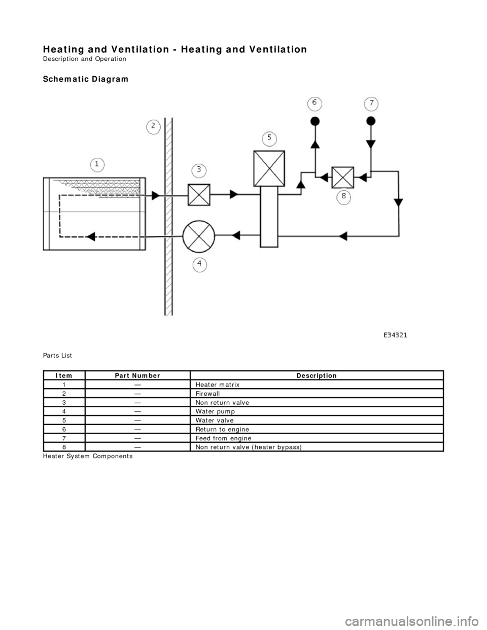
Heating and Ventilation - Heating and Ventilation
Description and Operation
Schematic Diagram
Parts List
Heater System Components
ItemPart NumberDescription
1—Heater matrix
2—Firewall
3—Non return valve
4—Water pump
5—Water valve
6—Return to engine
7—Feed from engine
8—Non return valve (heater bypass)