load capacity JAGUAR X308 1998 2.G Workshop Manual
[x] Cancel search | Manufacturer: JAGUAR, Model Year: 1998, Model line: X308, Model: JAGUAR X308 1998 2.GPages: 2490, PDF Size: 69.81 MB
Page 52 of 2490

Jacking and Lifting - Safety Precautions
Description and Operation
The following safety precautions must be observed wh en raising the vehicle to perform service operations:
Ne
ver rely on a jack alone to suppo
rt a vehicle; use suitable vehicle stands to provide rigid support.
When working ben
eath a vehicle, whenev
er possible use a ramp or inspection pit instead of a jack and vehicle
stands.
En
sure that the vehicle is
standing on firm, level grou nd before using a jack.
Do not rely
on the parking brake alon
e; chock the wheels and put the transmission into Park if possible.
Check that
any lifting equipment used has adequate capacity
for the load being lifted and is in proper working order.
Page 265 of 2490

W
heels and Tires - Wheels and Tires
D
iagnosis and Testing
General Not
es
1.
1. Factory in
stalled tires and wheels are designed to provide optimum ride and ha
ndling characteristics when inflated
to the recommended inflation pressures, with vehicle loads not exceeding the full-rated load capacity.
2. 2. Correct tire pressures and driv ing technique have an important influence on tire life. Heavy cornering, excessively
rapid acceleration and unnecessary sharp braking increase tire wear.
3. 3. Replacement tires should follow the recommended:
Size
.
Speed
rating.
Load range. Radial c
onstruction type.
4. 4. The use of any other size or type of wheel / tire may seriously affect:
Safety. Ri
de.
Handlin
g.
Speed
ometer / odometer calibration.
Vehi
cle ground clearance.
Ti
re clearance between
body and chassis.
Wh
eel bearing life.
Brake cooli
ng.
5. 5. Wheels must be renewed when:
Impact damaged. Heavil
y corroded.
Porous W
heel stud holes or se
ats become damaged.
They h
ave excessive radial or lateral runout.
Safety Notes
• WAR
NINGS:
DO NOT MIX DIFFERENT TYPES OF TIRES ON THE SAM E VEHICLE, HANDLING MAY BE SERIOUSLY AFFECTED
RESULTING IN LOSS OF CONTROL.
DO NOT MIX DIFFERENT TYPES OF TIRES ON THE SAM E VEHICLE, HANDLING MAY BE SERIOUSLY AFFECTED
RESULTING IN LOSS OF CONTROL.
A TIRE AND WHEEL MUST ALWAYS BE CORRECTLY MATCHED. WIDER OR NARROWER TIRES THAN RECOMMENDED
COULD CAUSE DANGER THROUGH SUDDEN DEFLATION.
WHEN USING THE TEMPORARY SPARE WHEEL, SPEED MUST NOT EXCEED 80 KM/H (50 MPH). DRIVE WITH CAUTION
AND REPLACE WITH THE SPECIFIED WHEEL / TIRE ASSEMBLY AS SOON AS POSSIBLE.
TRACTION CONTROL (IF AVAILABLE) MUST NOT BE ENGAGED WITH THE TEMPORARY SPARE WHEEL FITTED.
Page 273 of 2490

The
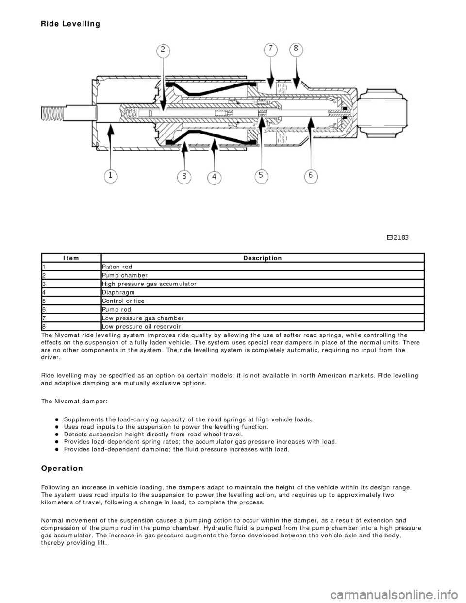
Nivomat ride levelling system improves ride quality by al
lowing the use of softer road springs, while controlling the
effects on the suspension of a fully laden vehicle. The system uses special rear dampers in place of the normal units. There
are no other components in th e system. The ride levelling system is comple tely automatic, requiring no input from the
driver.
Ride levelling may be specified as an opti on on certain models; it is not available in north American markets. Ride levelling
and adaptive damping are mu tually exclusive options.
The Nivomat damper:
Su
pplements the load-carrying capacity of th
e road springs at high vehicle loads.
Uses road inputs to the
suspension to power the levelling function.
De
tects suspension height dire
ctly from road wheel travel.
Provi
des load-dependent spring rates; the ac
cumulator gas pressure increases with load.
Pr
ovides load-dependent damping; the fluid pressure increases with load.
Op
eration
F
ollowing an increase in vehicle loading,
the dampers adapt to maintain the height of the vehicle within its design range.
The system uses road inputs to the suspension to power the levelling action, and requires up to approximately two
kilometers of travel, following a change in load, to complete the process.
Normal movement of the suspension caus es a pumping action to occur within the damper, as a result of extension and
compression of the pump rod in the pump chamber. Hydraulic fluid is pumped from the pump cham ber into a high pressure
gas accumulator. The increase in gas pressure augments the force developed between th e vehicle axle and the body,
thereby providing lift.
It
em
De
scription
1Pi
ston rod
2Pum
p chamber
3High
pressure
gas accumulator
4Diaphragm
5Co
ntrol orifice
6Pump rod
7Low pressure gas ch
amber
8Low pressure oil
reservoir
Ride Levelling