rear seat JAGUAR X308 1998 2.G Workshop Manual
[x] Cancel search | Manufacturer: JAGUAR, Model Year: 1998, Model line: X308, Model: JAGUAR X308 1998 2.GPages: 2490, PDF Size: 69.81 MB
Page 3 of 2490

Rear Toe Adjustment (57.65. 08)
Whee
l
Bearing Circlip Inspection
Wheel Bearing Inspection
204‐01: Front Suspension
Specification
Description and Operation
Front Suspension
Removal and Installation
Ball Joint (60.15.02)
Rear Lower Arm (60.35.54)
Rear Lower Arm Bushing (60.35.56)
Front Shock Absorber (60.30.04)
Spring
Spring Seat (60.20.03)
Front Sta
bilizer Bar (60.10.01)
Front Stabilizer Bar Bushing (60.10.04)
Front Stabilizer Bar Link (60.10.02)
Upper Arm Bushing
Front Wheel Bearing (60.25.40)
Wheel Hub
Wheel Knuckle (60.25.23)
Wheel Knuckle and Wheel Hub Assembly (60.25.38.90)
Wheel Knuckle and Wheel Hub Assembly Conversion (60.25.43)
204‐02: Rear Suspension
Specif
ication
Description and Operation
Rear Suspension
Removal and Installation
Axle Bump Stop (64.30.15)
Rear Suspension and Axle Assembly (64.25.01)
Rear Shock Absorber (64.30.02)
Shock Absorber Lower Bushing (64.30.39)
Spring (64.20.01)
Rear Stabilizer Bar (64.35.08) ‐ 4.0L SC V8 ‐ AJ26
Rear Stabilizer Bar Bushing (64.35.18) ‐ 4.0L SC V8 ‐ AJ26
Page 27 of 2490

419:
Electronic Featu r
e
Group
419
‐10:
Multifunction Electronic Modules
Removal
and Installation
Driver
Seat Module (DSM) (86.75.28)
5: Body and Paint
501: Body and Paint
501‐00: Body System ‐ Gen
eral Information
Specification
Description and Operation
Body
501‐02: Front End Body Panels
Description and Operation
Front End Body Panels
Removal and Installation
Cowl Panel Grille (76.10.01) (76.43.39)
Driver Side Bulkhead Cover (76.11.34)
Passenger Side Bulkhead Cover (76.11.33)
Radiator Grille Opening Panel (76.10.06)
Radiator Grille Ope
ning Panel Reinforcement (76.11.24)
Radiator Splash Shield (76.22.90)
501‐03: Body Closures
Description and Operation
Body Closures
General Procedures
Hood Alignment (76.16.02)
Diagnosi
s
and Testing
(FDM)
Front
Door Module
(86.80.34)
Rear
(RDM)
Door
Module
Page 30 of 2490

501‐10: Seating
Specificatio
n
Description and Operation
Seats
Removal and Installation
Front Seat (76.70.01)
Front Seat Backrest (76.70.06)
Front Seat Backrest Cover (76.70.15)
Front Seat Backrest Heater Mat (86.75.14)
Front Seat Backrest Trim Panel (76.70.03)
Front Seat Cushion (76.70.11)
Front Seat Cushion Cover (76.70.33)
Front Sea
t Cushion Heater Mat (86.75.13)
Front Seat Head Restraint (76.70.14)
Front Seat Head Restraint Motor (86.75.17)
Front Seat Recliner Motor (86.75.04)
Front Seat Track (76.70.20)
Front Seat Track Motor (86.75.33)
Lumbar Motor (86.75.12)
Rear Seat Armrest (76.70.39)
Rear Seat Backrest (76.70.38)
Rear Seat Backrest Cover (76.70.48) (78.90.12)
Rear Seat Backrest Heater Mat (86.75.35)
Rear Seat Cushio
n (76.70.37)
Rear Seat Cushion Cover (76.70.47)
Rear Seat Cushion Heater Mat (86.75.37)
Rear Seat Head Restraint (76.70.56)
Rear Seat Track
Seat Control Switch (86.75.23)
501‐11: Glass, Frames and Mechanisms
Description and Operation
Glass, Fra
mes and Mechanisms
Removal and Installation
Door Window Control Switch Bulb (86.46.12)
Front Door Window Glass (76.31.01)
Front Door Window Glass Weatherstrip (76.40.28)
Page 70 of 2490
Upper
Wishbones
Each
upper wi
shbone assembly is a on
e-piece steel forging incorporating:
A pres
s-fit ball joint.
Press-fi
t bushes for location of the upper fulcrum bolt.
Lower Wishbones
Each l
o
wer wishbone comprising
forged steel front and rear arms bolted together, incorporates:
A p
ress-fit ball joint in the outer extremity of the rear arm.
Press-f
i
t bushes for location of the lower fulcrum bolts
Locati
on for the shock absor
b
er lower mounting plates.
Vertica l Links
The vertical
links are of forged steel
wi
th integral steering arms. Each is suppo rted between the upper and lower wishbones
by two ball joints and carries:
Front hub
Brake ca
liper and disc shield assembly
ABS se
nsor
.
Front Hub
s
Each f
o
rged steel front hub accommodates sealed for life cartridge
type wheel bearings, and carries:
The brake rotor assembl
y.
A
h
ub nut with toothed, integral ABS rotor.
Su
s
pension spring pi
n locking device.
Front Road
Springs
The road spri
ng
s are of coil type with their
rating dependent upon vehicle specification
Ea
ch spring is installed between the suspension crossbeam location and the lower wishbone spring pan.
Ru
bber seats ar
e installed betw
een the spring and the crossb eam and the spring pan.
Front Shock A
bsorbers
Th
e
shock absorbers are telescopic hydrau
lically operated units. Optional adaptive damping units incorporate a solenoid-
operated control valve at their upper extremity.
Each shoc
k absorber is installed between the lowe
r wishbone rear arm and a recess in the body.
The l
o
wer end of the shock absorber is se
cured to plates on the wishbone by a bolt that also serves as a pivot.
The u
pper en
d of each shock absorber is secured to the body location by a single nut.
Front Sta
b
ilizer Bar
A
front stabil
izer bar installed on all vehicles
is rated according to suspension specification.
Opera
tion
As each road wheel r
i
ses, move
ment is transmitted through the vertical link assembly to the lower wishbone. The resulting
rise of the wishbone compresses the road spring and partially telescopes the shock absorber. During this action, the spring
absorbs associated shocks and the shock absorber minimizes sprin
g os c
illation.
Du
ring cornering, vehicle weight
is transferred to the outer road wheel with a resulting tendency for the inner wheel to lift.
The stabilizer bar assists in minimizing this tendency by transf erring a proportion of potential lift of the inner wheel to the
outer wheel. This result s in enhanced body stability with improved corner ing capabilities.
Page 75 of 2490
I
nstallation
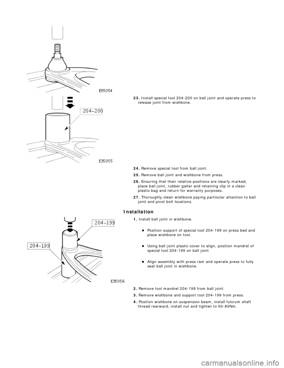
23
.
Install special tool 204-200 on ball joint and operate press to
release joint from wishbone.
24. Remove special tool from ball joint.
25. Remove ball joint and wishbone from press.
26. Ensuring that their relative positions are clearly marked,
place ball joint, rubber gaiter and retaining clip in a clean
plastic bag and return for warranty purposes.
27. Thoroughly clean wishbone paying particular attention to ball
joint and pivot bolt locations.
1. Inst
all ball joint in wishbone.
Pos
ition support of special tool 204-199 on press bed and
place wishbone on tool.
U
sing ball joint plastic cover to align, position mandrel of
special tool 204-199 on ball joint
Ali
gn assembly with press ram and operate press to fully
seat ball joint in wishbone.
2. Remove tool mandrel 204-199 from ball joint.
3. Remove wishbone and support tool 204-199 from press.
4. Position wishbone on suspensi on beam, install fulcrum shaft
thread rearward, install nu t and tighten to 60-80Nm.
Page 132 of 2490

2. Apply a su
itable lubricant to exterior of each half-bush.
3. Install soft covers to vise jaws.
4. Install half-bush
/spacer tu
be assembly in wishbone.
1. Align half-bush/spacer tube assembly with wishbone bore.
2. Position wishbone and half bush/spacer tube assembly between vise jaws.
Cl
ose vise jaws until half-bush/tube assembly is fully
seated in wishbone.
5. Remove wishbone from vise.
6. Instal
l second half-bush in wishbone.
1. Align and engage second half-bush with installed
spacer tube.
2. Position wishbone and half bush assembly between vise jaws.
Close
vise jaws until second half-bush assembly is fully
seated.
7. Remove wishbone from vise.
8. Following steps 1 to 7, install final bush assembly to wishbone.
9. Inst al
l wishbone on crossbeam.
Posi
ti
on wishbone on crossbeam.
Install
fulcrum shaft with threaded end rearward.
Install nut an
d tighten to 60-80Nm.
10. Remove wire temporarily securing vertical link to road spring.
Page 168 of 2490
Each r
oad spring and is located between the wishbone in
tegral spring seat and the body suspension turret.
Each shoc
k absorber unit is installed
co-axially within the road spring.
The lo
wer end of each shock absorber is secured to the
wishbone by a bolt which also functions as a pivot.
Adaptive damping is av
ailable as an option.
A
rear stabi
lizer bar is installed on
Supercharged and Sport Suspension models . Mounted at the rear of the wishbone
tie assembly, the stabilizer bar is connected to the wishbone by short links.
Op era
tion
As each road wheel r
i
ses, move
ment is transmitted through th e hub carrier assembly to the wishbone and axle shaft. The
corresponding rise of the wishbone compre sses the road spring and partially telescopes the shock absorber. During this
action, the spring absorbs result ing shocks and the shock absorber minimizes spring oscillation.
During cornering, vehicle weight is transferred to the outer road wheel with a resulting tendency for the inner wheel to lift.
On Supercharged and Sport Suspension vehicl es, a rear stabilizer bar assists in minimizing this tendency by transferring a
proportion of potential lift of the inner wheel to the outer wheel. This results in enhanced body stability with improved
cornering capabilities.
Page 272 of 2490
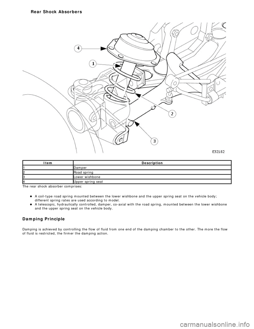
The rear shock ab
sorber comprises:
A
c
oil-type road spring mounted between the lower wish
bone and the upper spring seat on the vehicle body;
different spring rates are used according to model.
A te
lescopic, hydraulically controlled, damper, co-axial wi
th the road spring, mounted between the lower wishbone
and the upper spring seat on the vehicle body.
Damp
ing Principle
D
a
mping is achieved by controlling the flow of fluid from one
end of the damping chamber to the other. The more the flow
of fluid is restricted, the firmer the damping action.
Ite
m
De
scr
iption
1Dam
p
er
2Ro
ad s
pring
3Lower wishbon
e
4Upper sprin
g seat
Rear Shock A
b
sorbers
Page 343 of 2490
Front Disc Brake - Brake CaliperVehicles
With: Standard Brakes
Re
moval and Installation
Remov
al
W
ARNING: BRAKE DUST, IF INHALED CAN DAMAGE YOUR
HEALTH. ALWAYS REMOVE BRAKE DUST USING A VACUUM
BRUSH. DO NOT USE A COMPRESSED-AIR LINE TO DISPERSE BRAKE DUST INTO THE ATMOSPHERE.
• CAUTIONS:
Replacement of nuts and bolts: Various thread-locking de vices are used on nuts and bolts throughout the vehicle.
These devices restrict the number of times a nut or bolt can be used. See section 100-00 for information.
Remove brake fluid spilla ge immediately from paint work, with clean water.
A new brake hose must be installe d when replacing a brake caliper.
The brake pad adhesive backing must not be reused, therefore always install new brake pads, irrespective of the
condition of the original pads when replacing a brake caliper. Always replace brake pads as an axle set.
S
pecial Tool(s)
Brake Pedal
Hold Tool
JDS 9013
1. O
pen engine compartment and fit
paint work protection covers
to fenders.
2. Raise vehicle on a four-post lift.
3. Raise front of vehicle and support on stands. Refer to Section
100-02.
4. Remove front wheels. See Section 204-04.
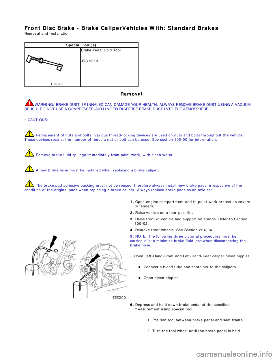
5. NOTE
: The following three pictorial procedures must be
carried-out to minimize brake fl uid loss when disconnecting the
brake hose.
Open Left-Hand-Front and Left-H and-Rear caliper bleed nipples.
Connect
a bleed tube and co
ntainer to the calipers.
O
pen bleed nipples.
6. Depress and hold down brak e pedal at the specified
measurement using special tool.
1. Position tool between brake pedal and seat frame.
2. Turn the tool wheel unti l the brake pedal is held
Page 368 of 2490
Rear Disc Brake - Brake CaliperVehicles W
ith: Standard Brakes
Re
mo
val and Installation
Remov
a
l
WA
RNING: BRAKE DUST, IF INHALED CAN DAMAGE YOUR
HEALTH. ALWAYS REMOVE BRAKE DUST USING A VACUUM
BRUSH. DO NOT USE A COMPRESSED-AIR LINE TO DISPERSE BRAKE DUST INTO THE ATMOSPHERE.
• CAUTIONS:
Replacement of nuts and bolts: Various thread-locking de vices are used on nuts and bolts throughout the vehicle.
These devices restrict the number of times a nut or bolt can be used. See section 100-00 for information.
Remove brake fluid spilla ge immediately from paint work, with clean water.
The brake pad adhesive backing must not be reused, therefore always install new brake pads, irrespective of the
condition of the original pads when replacing a brake caliper. Always replace brake pads as an axle set.
Sp
ecial Tool(s)
Brake Pedal
H
old Tool
JDS 9013
1. Op
en luggage compartment lid and fit suitable paintwork
protection equipment.
2. Raise vehicle on a four-post lift.
3. Raise rear of vehicl e and support on stan ds. See Section 100-
02.
4. Remove rear wheel. See Section 204-04.
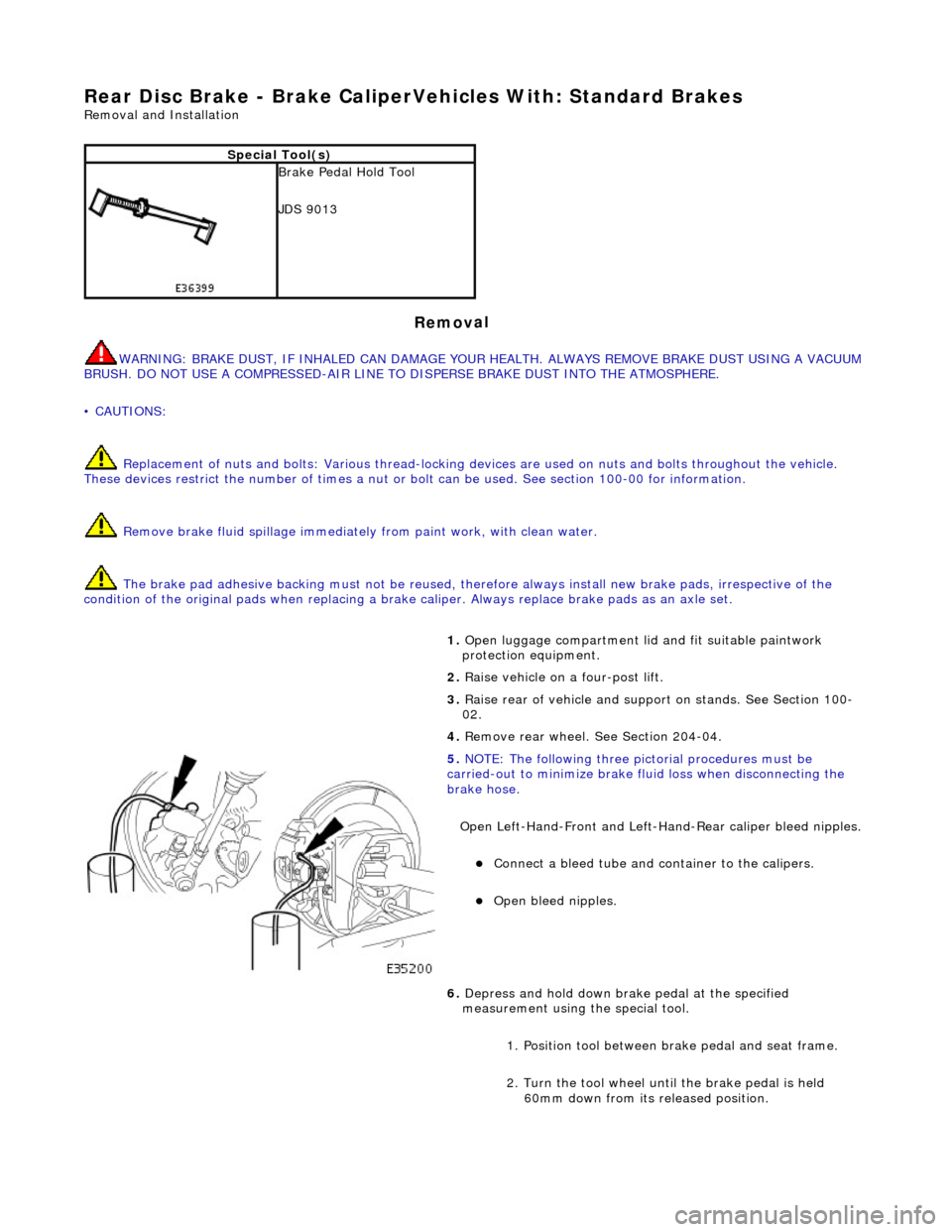
5. NOTE
: Th
e following three pictorial procedures must be
carried-out to minimize brake fl uid loss when disconnecting the
brake hose.
Open Left-Hand-Front and Left-H and-Rear caliper bleed nipples.
Connect a
bleed tube and co
ntainer to the calipers.
Op
en bleed nipples.
6. Depress and hold down brak e pedal at the specified
measurement using the special tool.
1. Position tool between brake pedal and seat frame.
2. Turn the tool wheel unti l the brake pedal is held
60mm down from its released position.