remove seats JAGUAR X308 1998 2.G Workshop Manual
[x] Cancel search | Manufacturer: JAGUAR, Model Year: 1998, Model line: X308, Model: JAGUAR X308 1998 2.GPages: 2490, PDF Size: 69.81 MB
Page 38 of 2490
Torque Specifications
Torque sp
ecifications are shown in maintenance procedure illustra
tions and also in the torque specifications chart located at
the front of the relevant section.
Disconnecting/Connecting the Battery
Ow ing t
o the electronic components used on the vehicle, it is important that the battery is disconnected when specified in a
maintenance procedure.
When the battery is connected, the specified procedure must be followed, to ensure the correct operation of all vehicle
systems; refer to Section 414-01.
Use of Control Modules
Control modu les may
only be used on the ve
hicle to which they were originally fitted. Do not attempt to use or test a control
module on any other vehicle.
Function
al Test
On
completion of a maintenance procedure, a thorough test should be carried out, to ensu
re that the relevant vehicle
systems are working correctly.
Protecting the Vehicle
Al ways
fit covers to protect
the fenders before commencing work in the engi ne compartment. Cover the seats and carpets,
wear clean overalls and wash hands or wear gloves before working inside the vehicle. Avoid spilling hydraulic fluid,
antifreeze or battery acid on the paintwork. In the event of spillage, wash off with water imme diately. Use polythene sheets
in the trunk to protect carpets. Always use the recommended service tool, or a satisfactory equivalent, where specified.
Protect temporarily exposed screw thread s by replacing nuts or fitting caps.
Preparation
Before disassembly, clean the surrounding ar ea
as thoroughly as possible. When co
mponents have been removed, blank off
any exposed openings using grease-proof paper and masking tape. Immediately seal fuel, oil and hydraulic lines when
separated, using plastic caps or plugs, to prevent loss of fluid and the entry of dirt. Close the open ends of oilways, exposed
by component removal, with tapered hardw ood plugs or readily visible plastic plugs. Immediately a component is removed,
place it in a suitable container; use a se parate container for each component and its associated pa rts. Before dismantling a
component, clean it thoroughly with a recommended cleaning agent; check that the agent will not damage any of the
materials within the component. Clean the bench and obtain ma rking materials, labels, containers and locking wire before
dismantling a component.
Dismantling
O b
serve scrupulous cleanliness when dismantling components,
particularly when parts of the brake, fuel or hydraulic
systems are being worked on. A particle of dirt or a fragment of cloth could caus e a dangerous malfunction if trapped in
these systems. Clean all tapped holes, crev ices, oilways and fluid passages with compressed air. Do not permit compressed
air to enter an open wound. Always use ey e protection when using compressed air.
Ensure that any O-rings used for sealing are correctly refitted or renewed if disturbed. Mark mating parts to ensure that
they are replaced as dismantled. Whenever possible use markin g materials which avoid the possibilities of causing distortion
or the initiation of cracks, which could occur if a center pu nch or scriber were used. Wire together mating parts where
necessary to prevent accidental interchange (e.g roller bearing components). Tie labels on to all parts to be renewed and to
parts requiring further inspection before being passed fo r reassembly. Place labelled parts and other parts for rebuild in
separate containers. Do not disc ard a part which is due for renewal until it ha s been compared with the new part, to ensure
that the correct part has been obtained.
Page 110 of 2490
In
stallation
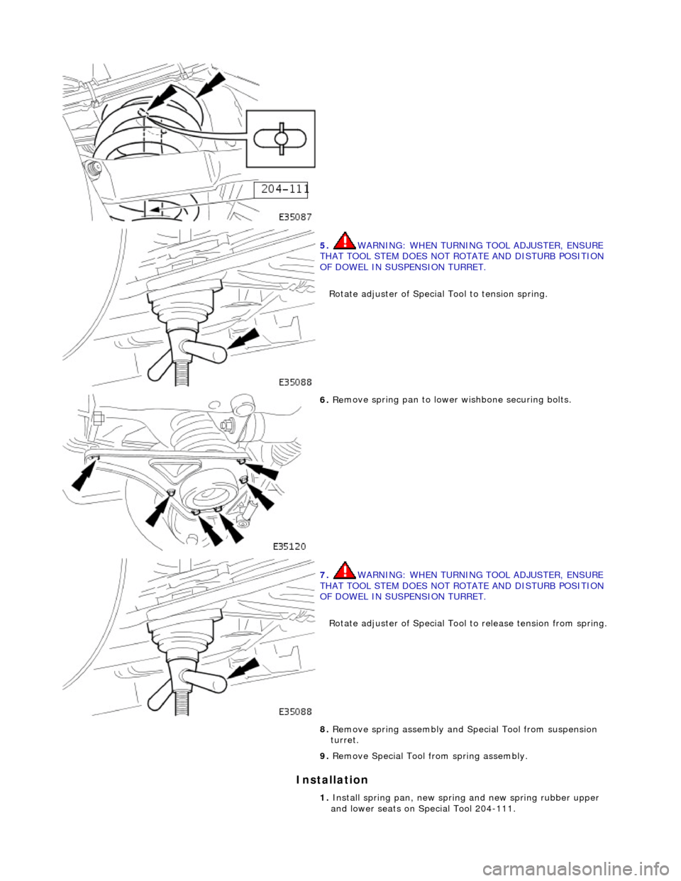
5.
WA
RNING: WHEN TURNING TOOL ADJUSTER, ENSURE
THAT TOOL STEM DOES NOT ROTATE AND DISTURB POSITION
OF DOWEL IN SUSPENSION TURRET.
Rotate adjuster of Special Tool to tension spring.
6. Re
move spring pan to lower
wishbone securing bolts.
7. WA
RNING: WHEN TURNING TOOL ADJUSTER, ENSURE
THAT TOOL STEM DOES NOT ROTATE AND DISTURB POSITION
OF DOWEL IN SUSPENSION TURRET.
Rotate adjuster of Special Tool to release tension from spring.
8. Re
move spring assembly and Special Tool from suspension
turret.
9. Remove Special Tool from spring assembly.
1. Install spring pan, new spring and new spring rubber upper
and lower seats on Special Tool 204-111.
Page 114 of 2490
In
stallation
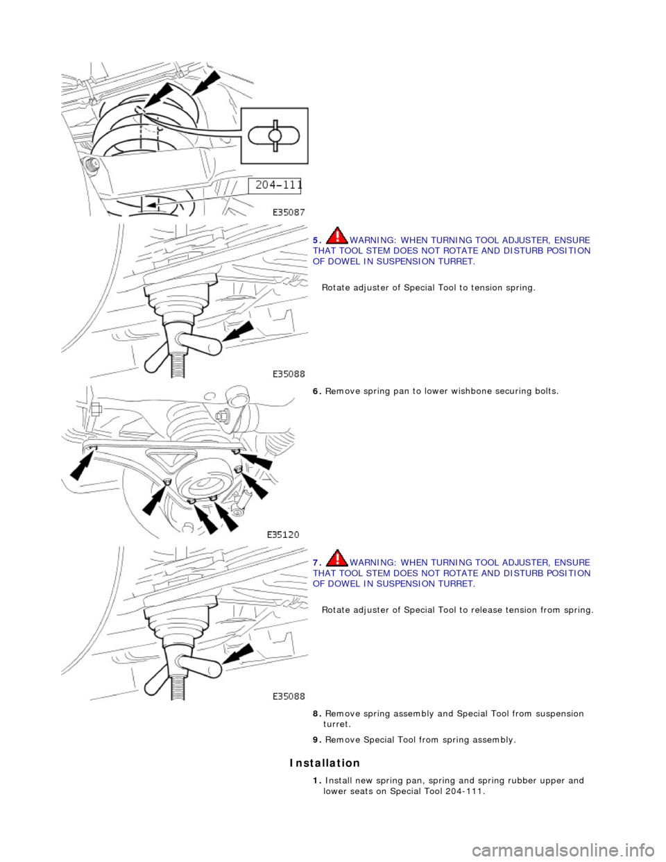
5.
WA
RNING: WHEN TURNING TOOL ADJUSTER, ENSURE
THAT TOOL STEM DOES NOT ROTATE AND DISTURB POSITION
OF DOWEL IN SUSPENSION TURRET.
Rotate adjuster of Special Tool to tension spring.
6. Re
move spring pan to lower
wishbone securing bolts.
7. WA
RNING: WHEN TURNING TOOL ADJUSTER, ENSURE
THAT TOOL STEM DOES NOT ROTATE AND DISTURB POSITION
OF DOWEL IN SUSPENSION TURRET.
Rotate adjuster of Special Tool to release tension from spring.
8. Re
move spring assembly and Special Tool from suspension
turret.
9. Remove Special Tool from spring assembly.
1. Install new spring pan, spring and spring rubber upper and
lower seats on Special Tool 204-111.
Page 205 of 2490
18
.
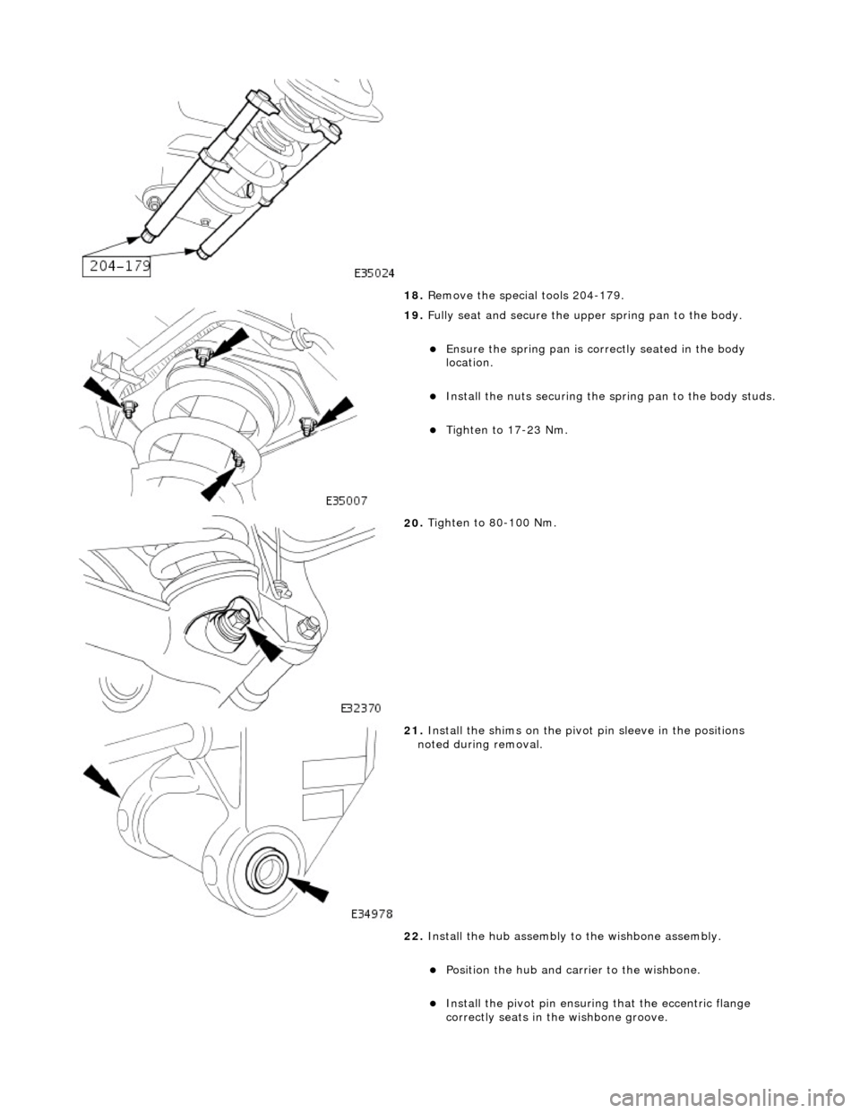
Remove the special tools 204-179.
19
.
Fully seat and secure the u pper spring pan to the body.
Ensure the spri
ng pan is correctly seated in the body
location.
Inst
all the nuts securing the sp
ring pan to the body studs.
Tigh
ten to 17-23 Nm.
20
.
Tighten to 80-100 Nm.
21
.
Install the shims on the pivot pin sleeve in the positions
noted during removal.
22. Install the hub assembly to the wishbone assembly.
Position the hub and carri
er to the wishbone.
Inst
all the pivot pin ensuring that the ecce
ntric flange
correctly seats in the wishbone groove.
Page 1148 of 2490
Evaporative E
missions - Evaporative Emissions
Description an
d Operation
To reduce the emission of fuel vapour, th e fuel tank is vented to atmosphere through activated charcoal adsorption canister
(s) which collects the fuel droplets. The ch arcoal is periodically purged of fuel when the EVAP Canister Purge Valve opens
the vapour line between the canister(s) and the air intake induct ion elbow. This action allows manifold depression to draw
air through the canister atmospheric vent, taking up the deposited fuel from the charcoal adsorber and burning the resulting
fuel vapour in the engine.
The EVAP Canister Purge Valve is controlled by the engine management system ECM. Purging is carried out in accordance
with the engine management fu eling strategy (see below).
The fuel tank vapour outlet is via a removeable flange assemb ly on the top surface of the tank. The vapour storage canister
or canisters are fitted on the underside of the vehicle below the rear seats.
There are three variants of the evaporativ e system. All systems use the charcoal adsorber storage canisters and purge valve
and operate as described above. The specific features of each system are described below. The evaporative systems are
designated as :
sin g
le canister system
ru
nn
ing loss system
ru
nn
ing loss with On-board Re-fueling Vapour Recovery (ORVR) system
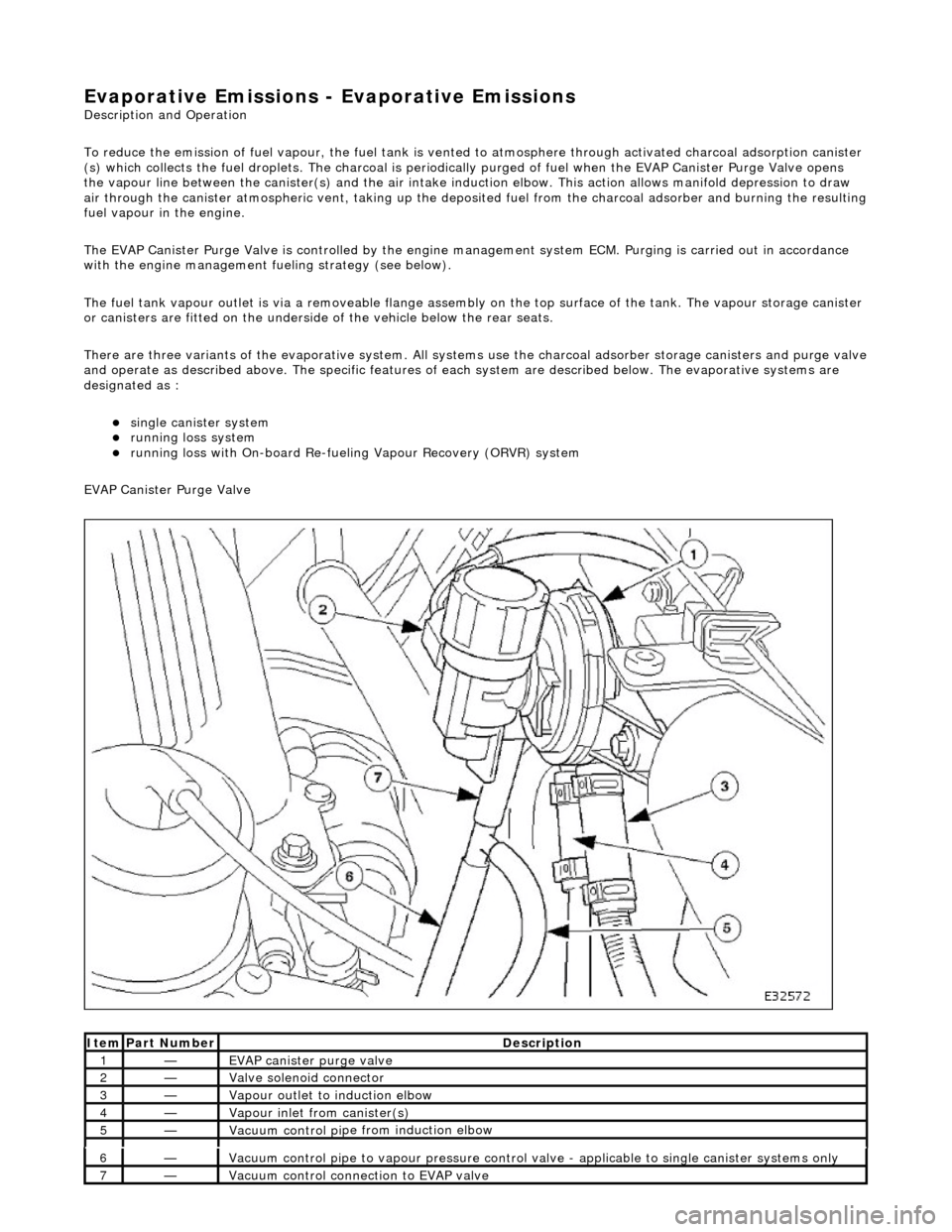
EVAP Canister Purge Valve
Ite
m
Par
t
Number
De
scr
iption
1—EVAP canister purge v
alve
2—Valve s
olenoid connector
3—Vapour outlet to indu
ction elbow
4—Vapour
inlet from canister(s)
5—Vacuum contro
l pi
pe from induction elbow
6—Vacuum contro
l pi
pe to vapour pressure control va
lve - applicable to single canister systems only
7—Vacuum
control connection to EVAP valve
Page 1937 of 2490

Exterior Lighting - High Beam Headlamp
Removal and Installation
Removal
Installation
1. Remove headlamp assembly fo r access. Refer to 86.41.33.
2. Release bulb holder securing tangs and position holder for
access.
3. Rotate pilot bulb holder 1/4 turn and withdraw holder.
4. Invert headlamp assembly.
5. Release headlamp unit adju sting screws and pivot.
1. Install headlamp unit on adjusting screw and pivot seats.
Page 1945 of 2490

Exterior
Lighting - License Plate Lamp
Rem
oval and Installation
Remov
al
Installation
1.
Remove battery cover and disconnect ground cable from battery
terminal. Refer to 86.15.19.
2. Remove trunk lamp assemblies. Refer to 86.45.16
3. Remove trunk lid upper trim finisher. Refer to 76.43.79.
4.
From inside trunk lid, press tang at each side of lamp and push
lamp outwards.
5.
Withdraw number plate lamp from trunk lid for access and
disconnect lamp harness multiplug.
6.
Remove and discard foam seal from lamp.
1. Install new foam seal to number plate lamp.
2. Position number plate lamp at trunk lid and connect harness
multiplug.
3. Install number plate lamp in trunk lid aperture ensuring that seal
seats correctly.
4. Install trunk upper trim finisher. Refer to 76.43.79.
5. Install trunk lamp assemb lies. Refer to 86.45.16.
6. Connect ground cable to battery terminal and fit battery cover.
Refer to 86.15.15.
Page 1947 of 2490

Exterior Lighting - Low Beam HeadlampVehicles Without: Headlamp
Leveling
Removal and Installation
Removal
Installation
1. Remove headlamp assembly fo r access. Refer to 86.41.33.
2. Release bulb holder securing tangs and withdraw holder for
access.
3. Invert headlamp assembly.
4. Release headlamp unit adju sting screws and pivot.
1. Install headlamp unit adjusting screws and pivot in locating
seats.
2. Invert headlamp assembly.
3. Install headlamp assembly bulb holder.
Page 1949 of 2490

Exterior Lighting - Low Beam HeadlampVehicles With: Headlamp Leveling
Removal and Installation
Removal
Installation
1.
Remove headlamp assembly for access. Refer to 86.41.33.
2. Release bulb holder securing tangs and withdraw holder for
access.
3. Invert headlamp assembly.
4. Release headlamp unit adjusting screws and pivot.
5. Remove actuator.
1. Release headlamp unit from leveling actuator adjusting screw.
2. Rotate actuator 1/4 turn inward, tilt forward end
downward and withdraw assembly from headlamp.
1. Install headlamp unit adjusting screws and pivot in locating
seats.
2. Invert headlamp assembly and install bulb holder.
3. With forward end tilted downward, position actuator assembly on
headlamp mounting.
4. Align actuator with headlamp and rotate it 1/4 turn outwards to
engage and fully seat in mounting.
5. Install headlamp assembly. Refer to 86.41.33.
6. Align headlamp beams.
Page 2028 of 2490
Front End Body Panels - Cowl Panel Grille
Removal and Installation
Installation
1.
Open the hood and fit fender covers.
2. Remove the wiper arm and blade assembly. Refer to
84.15.44.90.
3. Slacken and remove the five pl enum cover securing screws.
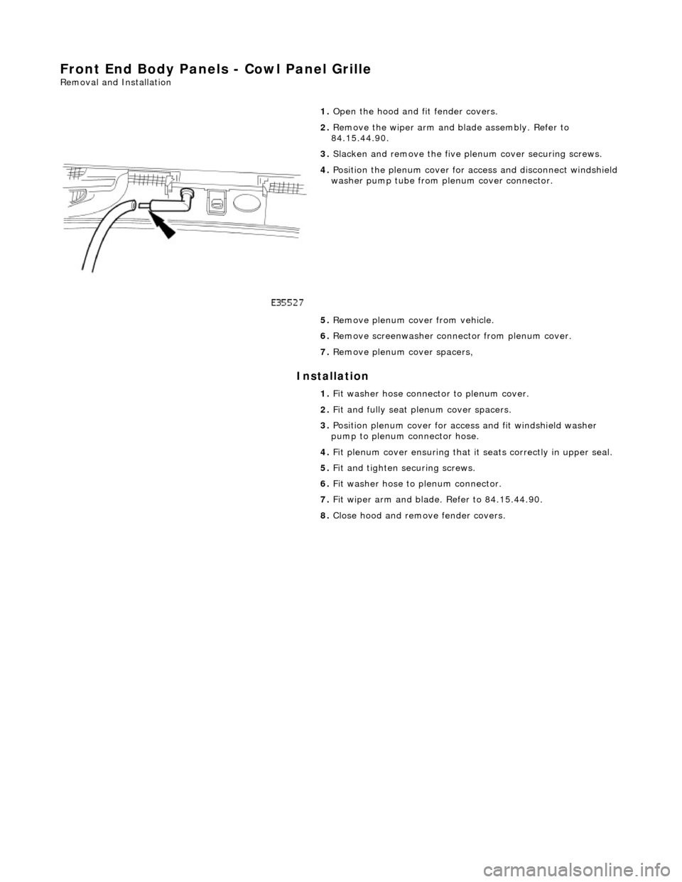
4. Position the plenum cover for access and disconnect windshield
washer pump tube from pl enum cover connector.
5. Remove plenum cover from vehicle.
6. Remove screenwasher conne ctor from plenum cover.
7. Remove plenum cover spacers,
1. Fit washer hose connector to plenum cover.
2. Fit and fully seat plenum cover spacers.
3. Position plenum cover for access and fit windshield washer
pump to plenum connector hose.
4. Fit plenum cover ensuring that it seats correctly in upper seal.
5. Fit and tighten securing screws.
6. Fit washer hose to plenum connector.
7. Fit wiper arm and blade. Refer to 84.15.44.90.
8. Close hood and remove fender covers.