road wheel nuts JAGUAR X308 1998 2.G Workshop Manual
[x] Cancel search | Manufacturer: JAGUAR, Model Year: 1998, Model line: X308, Model: JAGUAR X308 1998 2.GPages: 2490, PDF Size: 69.81 MB
Page 78 of 2490

Front Suspension - Rear Lower Arm
Remo
val and Installation
Remov
a
l
CAUTI
O
N: Replacement of
nuts and bolts: Various thread-locking devices are used on nuts and bolts throughout the
vehicle. These devices restrict the number of times a nut or bolt can be used. Refer to Section 100-00 for further
information.
S p
ecial Tool(s)
R
o
ad spring compressor
204-111 (JD115)
Taper separator
2
11-098 (JD 100)
Ball
Jo
int Taper Separator
204-192 (JD 219)
Bal l
joint splitter
204-293
1. Ra
ise front of vehicle and support on stands. Refer to Section
100-02.
2. Remove appropriate road wheel. Refer to Section 100-02.
3. CAUTIO
N: Do not suspend caliper from brake hose as
this will damage the hose.
Remove brake calipers from carriers. 1. Remove caliper spring clip.
2. Remove guide pin dust caps.
3. Slacken and withdraw guide pins.
4. Remove caliper from carrier and tie to suspension mounting bracket.
4. Ra
ise vehicle further to provid
e access for Special Tool 204-
Page 90 of 2490

Front Suspension - Rear Lower Arm Bushing
Remo
val and Installation
Remov
a
l
CAUTI
O
N: Replacement of
nuts and bolts: Various thread-locking devices are used on nuts and bolts throughout the
vehicle. These devices restrict the number of times a nut or bolt can be used. Refer to Section 100-00 for further
information.
S p
ecial Tool(s)
R
o
ad spring compressor
204-111 (JD115)
Taper separator
2
11-098 (JD 100)
Ball
Jo
int Taper Separator
204-192 (JD 219)
Bal l
joint splitter
204-293
1. Ra
ise front of vehicle and support on stands. Refer to Section
100-02.
2. Remove appropriate road wheel. Refer to Section 100-02.
3. CAUTIO
N: Do not suspend caliper from brake hose as
this will damage the hose.
Remove brake calipers from carriers. 1. Remove caliper spring clip.
2. Remove guide pin dust caps.
3. Slacken and withdraw guide pins.
4. Remove caliper from carrier and tie to suspension mounting bracket.
4. Ra
ise vehicle further to provid
e access for Special Tool 204-
Page 109 of 2490
Front Suspension - Spring
Re
moval and Installation
Remov
al
CAUTI
ON: Replacement of
nuts and bolts: Various thread-locking devices are used on nuts and bolts throughout the
vehicle. These devices restrict the number of times a nut or bolt can be used. See section 100-00 for information.
S
pecial Tool(s)
R
oad spring compressor
204-111 (JD115)
Taper separator
211-098 (JD 100)
Ball
Joint Taper Separator
204-192 (JD 219)
1. R
aise front of vehicle to provid
e access for Special Tool 204-
111. Refer to Section 100-02
2. Remove appropriate road wheel. Refer to Section 100-02.
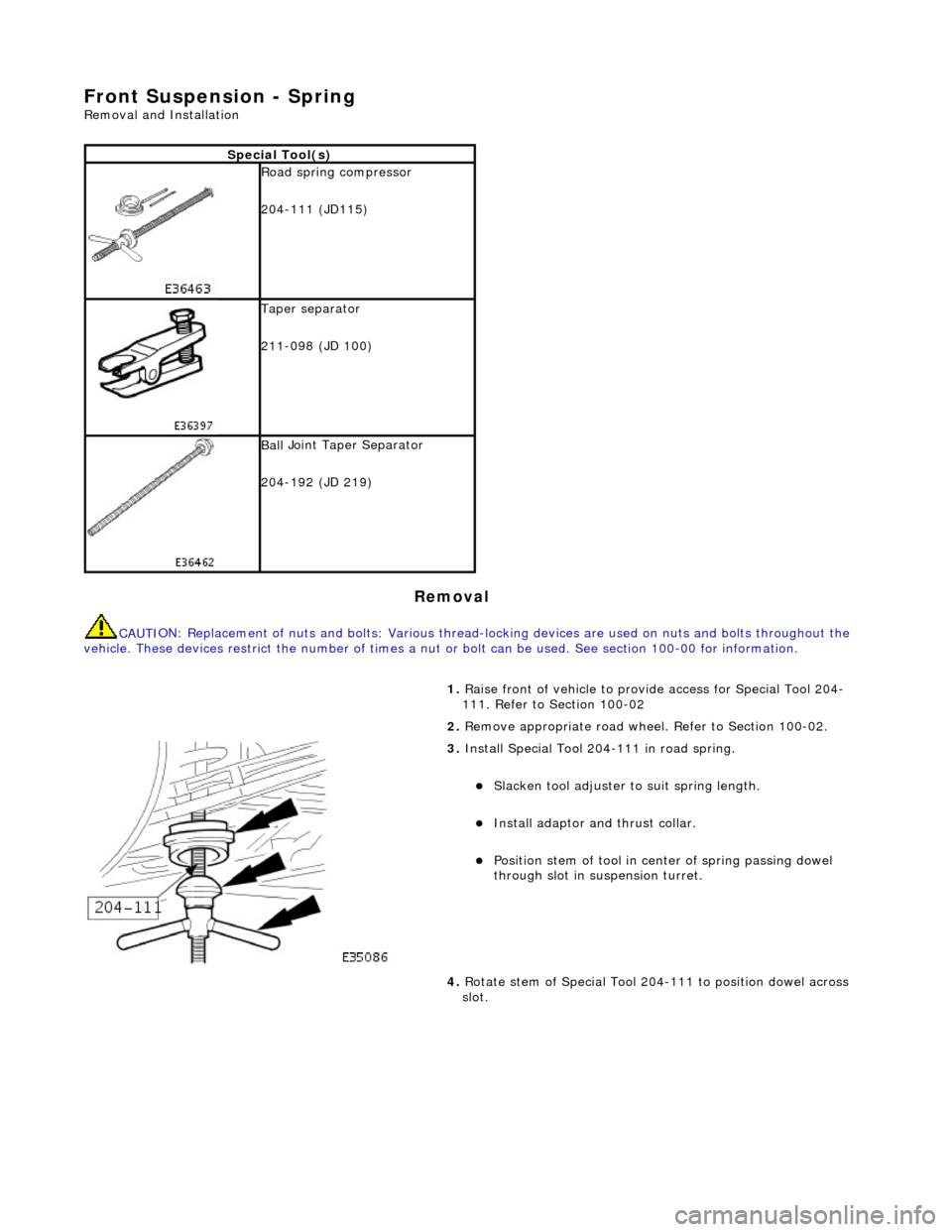
3. Ins
tall Special Tool 204-111 in road spring.
Sl
acken tool adjuster to suit spring length.
Install adaptor
and thrust collar.
Posit
ion stem of tool in center of spring passing dowel
through slot in su spension turret.
4. Rotate stem of Special Tool 204-111 to position dowel across
slot.
Page 113 of 2490
Front Suspension - Spring Seat
Re
moval and Installation
Remov
al
CAUTI
ON: Replacement of
nuts and bolts: Various thread-locking devices are used on nuts and bolts throughout the
vehicle. These devices restrict the number of times a nut or bolt can be used. See section 100-00 for information.
S
pecial Tool(s)
R
oad spring compressor
204-111 (JD115)
Taper separator
211-098 (JD 100)
Ball
Joint Taper Separator
204-192 (JD 219)
1. R
aise front of vehicle to provid
e access for Special Tool 204-
111. Refer to Section 100-02
2. Remove appropriate road wheel. Refer to Section 100-02.
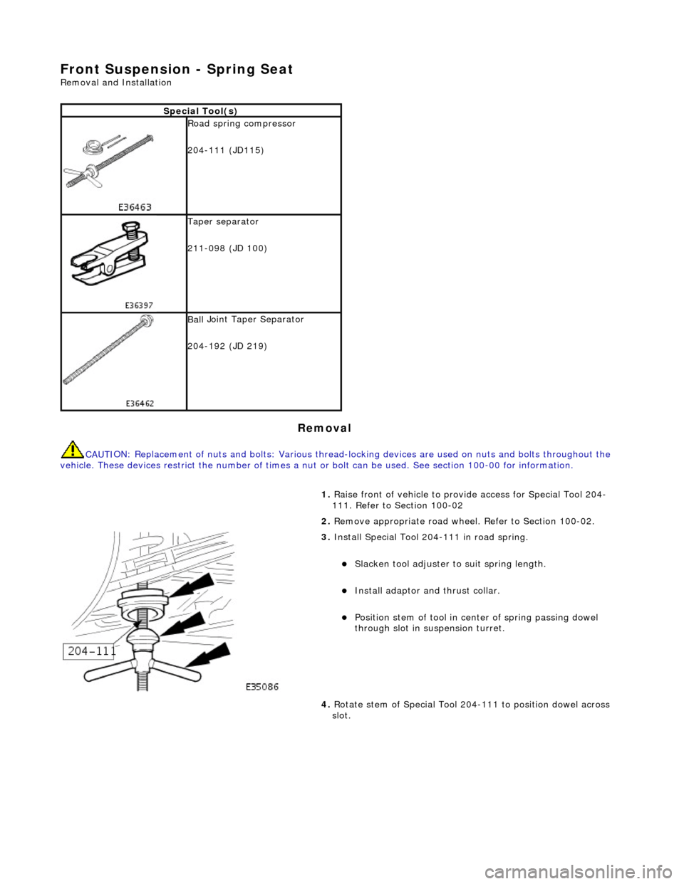
3. Ins
tall Special Tool 204-111 in road spring.
Sl
acken tool adjuster to suit spring length.
Install adaptor
and thrust collar.
Posit
ion stem of tool in center of spring passing dowel
through slot in su spension turret.
4. Rotate stem of Special Tool 204-111 to position dowel across
slot.
Page 142 of 2490

Remova
l
CAUTI
O
N: Replacement of
nuts and bolts: Various thread-locking devises are used on nuts and bolts throughout the
vehicle. These devises restrict the number of times a nut or bolt can be used. Refer to Section 100-00 for further
information.
1 8
G 1004
1.
Ra
ise front of vehicle and support on stands. Refer to Section
100-02.
2. Remove appropriate road wheel. Refer to Section 100-02.
3. Remove front brake disc. Refer to 70.10.12.
4. Remove vertical link and hub assembly. Refer to operation
60.25.38.90.
5. Re
move brake-disc shield from vertical link.
1. Remove screws.
2. Remove disc shield.
6. Us
ing special tool, secure vertical link and hub assembly in a
vise.
Secu re spe
cial tool 204-195 in a vise.
Posit
i
on hub in tool.
Inst
al
l wheel nuts.
7. Remove rotor nut spring-clip.
Page 148 of 2490

Remova
l
CAUTI
O
N: Replacement of
nuts and bolts: Various thread-locking devises are used on nuts and bolts throughout the
vehicle. These devises restrict the number of times a nut or bolt can be used. See section 100-00 for information.
1 8
G 1004
1.
Ra
ise front of vehicle and support on stands. Refer to Section
100-02.
2. Remove appropriate road wheel. Refer to Section 100-02.
3. Remove front brake disc. Refer to 70.10.12.
4. Remove vertical link and hub assembly. Refer to operation
60.25.38.90.
5. Re
move brake-disc shield from vertical link.
1. Remove screws.
2. Remove disc shield.
6. Us
ing special tool, secure vertical link and hub assembly in a
vise.
Secure special tool
in a vise.
Posit
i
on hub in tool.
Inst
al
l wheel nuts.
7. Re
move rotor nut spring-clip.
Page 169 of 2490
Rear Suspension - Axle B
ump Stop
Re
moval and Installation
Remov
al
CAUTI
ON: Replacement of
nuts and bolts: Various thread-locking devices are used on nuts and bolts throughout the
vehicle. These devices restrict the number of times a nut or bolt can be used. See section 100-00 for information.
I
nstallation
1.
R
aise rear of vehicle and support
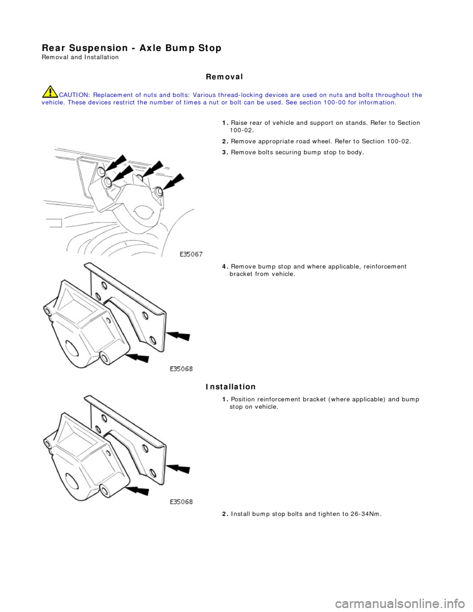
on stands. Refer to Section
100-02.
2. Remove appropriate road wheel. Refer to Section 100-02.
3. Remove bolts securing bump stop to body.
4. Remove bu
mp stop and where applicable, reinforcement
bracket from vehicle.
1. Position reinforcemen t brac
ket (where a
pplicable) and bump
stop on vehicle.
2. Install bump stop bolts and tighten to 26-34Nm.
Page 263 of 2490
O
ne locking wheel nut is fitted to each road wheel and can on
ly be removed by using the correctly coded socket. For road
wheels with exposed wheel nuts, each locking wheel nut is provided with a cover, which is removed using the cover removal
tool.
Locking wheel nuts have different coded keyway combinations with corresponding coded sockets. The correct socket, and
cover removal tool are supplied with the vehicle toolkit. Sets of sockets are available to Jaguar dealers.
Temporary Spare Wheel
•
NOTE: When using this type of spare wheel note that:
Speed
must not exceed 80 km/h (50 mph).
The normal ro
ad wheel must be reinstalled as soon as possible.
On
ly one temporary wheel may be installed to the vehicle.
Tracti
on control (where fitted
) must be switched OFF.
In certain markets, the spare wheel supplied with the vehicle is of the temporary-use type, it is narrower than the normal
road wheel and takes up less room in the luggage compartment.
Tire
s
The
radial ply tires shown in the 204-04
Specification Section are recommended by Jaguar to meet the high speed
performance of the vehicle. Only tires of identical specification may be fitted as replacements. Unde r no circumstances must
cross-ply tires be fitted.
Tire Inflation Pressures
Al
l recommended tires, including winter tire
s, must be inflated to the pressures shown in the 204-04 Specification Section.
Inflation pressures must only be checked when the tires are cold.
Tire Replac
ement and Wheel-Interchanging
W
hen renewal of tires is necessary, it is
preferable to fit a complete set. If two replacement tires are fitted (to one axle),
they must be of the same manufacturer and type as those on the other axle.
No attempt must be made to interchange wh eels from the front to the rear or vice-versa, as wear produc es a characteristic
pattern on each tire depending upon its po sition on the vehicle. If this position is changed after wear has occurred, the
performance of the tire w ill be adversely affected.
It should be remembered that new tires must be balanced befo re installing to the vehicle.
Win
ter Tires
•
NOTE: Speed must not exceed 210 km/h (131 mph) when winter tires are installed.
Jaguar recommended winter tires as specified in 204-04 Specification Section must only be fitted in complete four-wheel
sets of the same type and size.
Snow Chains and Spike Spider Traction System
Jagu
ar recommended snow chains, must on
ly be installed when using 16 inch wheels with 255/60 R16 winter tires.
• NOTE: When using snow chains or the spike spider traction system, note that:
Snow ch
ains and the spike spider
traction system must only be fitted to the rear wheels.
O
nly Jaguar recommended snow chains and spik
e spider traction system must be used.
The m
aximum permissible speed with winter tires and snow chains or the spike spider traction system fitted is 48
km/h (30 mph).
Tracti
on control (where fitted) must be
switched OFF when using snow chains or the spike spider traction system.
Page 266 of 2490
WHE
N CHANGING A WHEEL, ENSURE THAT THE VEHICLE CANNOT MOVE. ALWAYS APPLY THE PARK BRAKE AND
SELECT TRANSMISSION 'P' POSITION.
NEVER RUN THE ENGINE WITH ONE WHEEL OFF THE GROUND, FOR EXAMPLE, WHEN CHANGING THE WHEEL. THE
VEHICLE COULD MOVE.
TIGHTEN THE WHEEL NUTS TO SPECIFICATION. WHEELS MAY COME LOOSE IF OVER OR UNDER TIGHTENED.
USE WHEELS AND WHEEL NUTS DESI GNED FOR XJ SERIES VEHICLES ONLY. AFTERMARKET WHEELS OR WHEEL
NUTS MAY NOT FIT OR FUNCTION PROPERLY AND COULD CAUSE INJURY OR DAMAGE.
In
spection and Verification
To maximize ti
re performance, inspec
t the tires frequently for signs of:
Unev
en wear.
Incorrect
ti
re pressure.
Wh
ee
l imbalance.
Cuts. Abrasi
ons.
B
u
lges (blister).
Ply s
e
paration.
Embedded objects. Impact damage.
Inspe c
tion should be
more frequent when:
Continuo
us high speed op
eration is required.
Ra
pid or extreme temperatures changes occur.
R
o
ad surfaces are rough.
Roads ar
e littered
with debris.
Tread W
e
ar Indicator
•
NO
TE: Tire condition must comply with prevailing local legislation.
New tires must be installed if the wear in dicators are exposed or if there is severe shoulder wear. Shoulder wear is usually
caused by either excessive camber or toe on tires.
T i
re Vibration Diagnosis
A
tir
e vibration diagnostic procedure always
begins with a road test. The road test and the custom er interview (if available)
will provide much of the information need ed to find the source of vibration.
During the road test, drive the vehicle on a road that is smooth and free of undulations. If vibration is apparent, note and
record the following:
The s p
eed at which the vibration occurs.
W
h
at type of vibration occurs in each
speed range - mechanical or audible.
How the vibrati
on is affected
by changes in the following:
- -engine torque
- -vehicle speed
- -engine speed.
Type of v i
bration - sensitivity:
- - torque sensitive,
- - vehicle speed sensitive,
- - or engine speed sensitive.
Page 267 of 2490
The
following explanations will help isolate the source of vibration.
Torque Sensitive
This
means that the condition can be impr
oved or made worse by accelerating, dece lerating, coasting, maintaining a steady
vehicle speed, or applying engine torque.
Ve
hicle Speed Sensitive
This means th
at the vibration al
ways occurs at the same vehicle speed and is not affected by engine torque, engine speed
or gear selection.
Engine Speed Sensit
ive
This means th
at the vibration
occurs at varying vehicle spee ds when a different gear is selected. It can sometimes be
isolated by increasing or decreasing engine speed with the tran smission in neutral or by stall testing with the transmission in
gear. If the condition is engine speed sensitive, the cause is probably not related to tires.
If the road test indicates that there is tire wine, but no shake or vibration, the noise originates with the contact between th e
tire and the road surface.
A thumping noise usually means that the tire is flat or has soft spots making a noise as they slap the roadway. Tire whine
can be distinguished from axle no ise, as tire whine remains the same over a range of speeds.
Sym
ptom Chart
Sy
mptom Chart
Sy
mptom
Possib
le Sources
Acti
on
Uneven ti
re wear.
Incorrect ti
re inflation.
*
Cor
rect to specification.
*
Exce
ssive radial an
d lateral runout.
*
Renew tire
or wheel.
*
O
ut of specification steering
geometry.
*
R
ealign steering geometry: Refer to Section 204-
00.
*
W
orn ball joint.
*
Renew
damaged component, realign steering
geometry.
*
W
orn tie-rod end.
*
R
enew component, realign steering geometry.
*
Incorrect
tire / wheel usage.
*
Inst
all correct tire and wheel combination.
*
Loose or leaki
ng shock absorbers.
*
Tigh
ten or Renew as nece
ssary: Refer to Section
204-00.
*
Suspensi
on geometry out of
alignment.
*
Che
ck and adjust: Refer to Section 204-00.
*
Loose, worn or da mage
d suspension
components.
*
In
spect, Repair or Renew as necessary.
*
Wh
eel and tire assembly out of
balance.
*
Balance wheel an
d tire assembly.
*
Excessive later
al or radial runout of
wheel or tire.
*
Check, Repair o
r
Renew as required.
*
Tire
s show excess wear on
edge of treads.
Ti
res under-inflated.
*
Cor
rect pressure to specification.
*
Vehi
cle overloaded.
*
Cor
rect to specification.
*
Tire
s show excess wear on
edge of treads (with tire
pressures correct).
Incorre
ct toe setting.
*
Se
t to specification: Refer to Section 204-00.
*
Tire
s show excess wear in
center of tread.
Tire
s over-inflated.
*
Cor
rect pressure to specification
*
W
heel mounting is
difficult.
Incorrect app
lication or mismatched
parts, including wheel studs and
wheel nuts. Corroded, worn or
damaged parts.
*
Fol
low the manufacturer's specifications. Clean or
Renew.
*
Wobble or sh
immy
affecting wheel runout.
Damaged wh
eel (eventually
damaging wheel bearings and causing
uneven tire wear).
*
Inspect wheel rims for
damage and runout. Renew
as required.
*
Vehicle vibrations from
Tire
s / wheels mismatched.
*
Inst
all correct tire / wheel combination.
*