troubleshooting JAGUAR X308 1998 2.G Workshop Manual
[x] Cancel search | Manufacturer: JAGUAR, Model Year: 1998, Model line: X308, Model: JAGUAR X308 1998 2.GPages: 2490, PDF Size: 69.81 MB
Page 1015 of 2490

Fuel D
istribution
Fuel is supplied to th
e engine
via eight fuel injectors (one pe r cylinder). The injectors are located in two fuel rails which r un
the length of each cylinder bank and ar e integral with the air intake manifold.
Fuel pumped from the tank enters a feed pipe at the rear of bank 2. Fuel flow is along bank 2 fuel rail, across the top front
of the engine (cross-over pipe) and through bank 1 fuel rail, the unused fuel re turning to the tank via a pressure regulator.
The fuel injectors are each controlled electrically from the engine control module (ECM).
A test valve is fitted to the cross-over pipe connecting the fu el rails at the front of the intake manifold. This valve allows the
fuel system to be depr essurized during servicin g and troubleshooting.
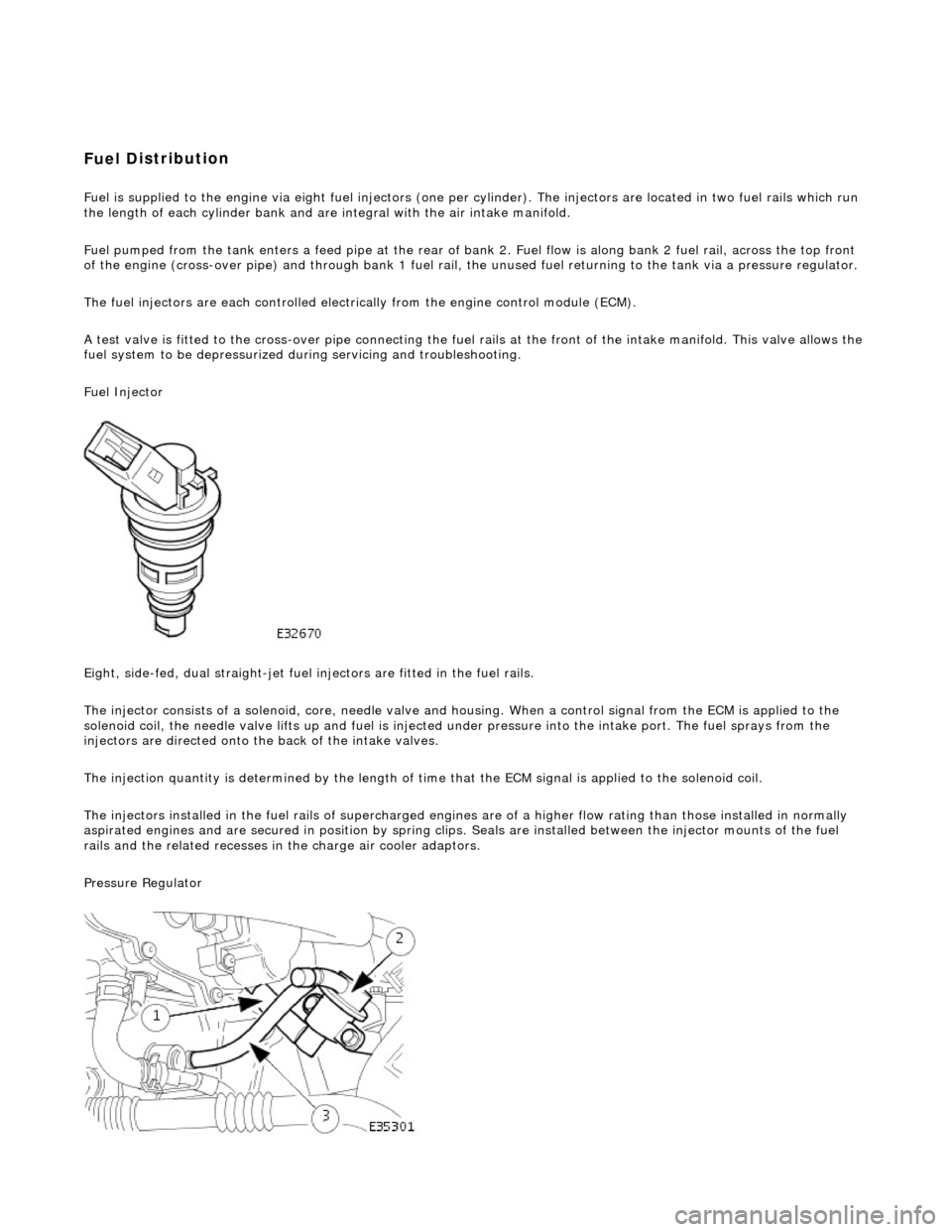
Fuel Injector
Eight, side-fed, dual straight-jet fuel injectors are fi tted in the fuel rails.
The injector consists of a solenoid, core, needle valve and ho using. When a control signal from the ECM is applied to the
solenoid coil, the needle valve lifts up and fuel is injected under pressure into the intake port. The fuel sprays from the
injectors are directed onto the back of the intake valves.
The injection quantity is determined by the length of time that the ECM signal is applied to the solenoid coil.
The injectors installed in the fuel rails of supercharged engines are of a higher flow rating than those installed in normally
aspirated engines and are secured in position by spring clips. Seals are instal led between the injector mounts of the fuel
rails and the related re cesses in the charge air cooler adaptors.
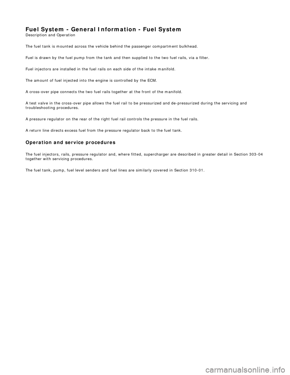
Pressure Regulator
Page 1688 of 2490

Fuel System - General Inform
ation - Fuel System
Description an
d Operation
The fuel tank is mounted across the vehicle behind the passenger compartment bulkhead.
Fuel is drawn by the fuel pump from the tank and then supplied to the two fuel rails, via a filter.
Fuel injectors are installed in the fuel ra ils on each side of the intake manifold.
The amount of fuel injected into th e engine is controlled by the ECM.
A cross-over pipe connects the two fuel ra ils together at the front of the manifold.
A test valve in the cross-over pipe allo ws the fuel rail to be pressurized and de-pressurized during the servicing and
troubleshooting procedures.
A pressure regulator on the rear of the right fuel rail controls the pressure in the fuel rails.
A return line directs excess fuel from the pressure regulator back to the fuel tank.
Operation and service procedures
The fuel injector
s, rails, pres
sure regulator and, wher e fitted, supercharger are described in greater detail in Section 303-04
together with servicing procedures.
The fuel tank, pump, fuel level senders and fuel lines are similarly covered in Section 310-01.