ignition coil JAGUAR XFR 2010 1.G Workshop Manual
[x] Cancel search | Manufacturer: JAGUAR, Model Year: 2010, Model line: XFR, Model: JAGUAR XFR 2010 1.GPages: 3039, PDF Size: 58.49 MB
Page 13 of 3039

Throttle Body303-05D: Accessory Drive - V8 S/C 5.0L PetrolSpecificationDescription and OperationComponent Location
OverviewRemoval and InstallationAccessory Drive Belt
Accessory Drive Belt Idler Pulley
Accessory Drive Belt Tensioner
Supercharger Belt Idler Pulley
Supercharger Belt Tensioner303-06C: Starting System - V8 5.0L Petrol/V8 S/C 5.0L PetrolSpecificationDescription and OperationComponent Location
Overview
System Operation and Component DescriptionDiagnosis and TestingStarting System
Starting System - Vehicles With: Smart KeyRemoval and InstallationStarter Motor303-07B: Engine Ignition - V8 5.0L Petrol/V8 S/C 5.0L PetrolSpecificationDescription and OperationComponent Location
Overview
System Operation and Component DescriptionDiagnosis and TestingEngine IgnitionRemoval and InstallationIgnition Coil-On-Plug - V8 S/C 5.0L Petrol303-08C: Engine Emission Control - V8 5.0L Petrol/V8 S/C 5.0L Petrol
Description and OperationComponent Location
Overview
System Operation and Component DescriptionDiagnosis and TestingEngine Emission Control303-12D: Intake Air Distribution and Filtering - V8 S/C 5.0L PetrolSpecification
Page 54 of 3039
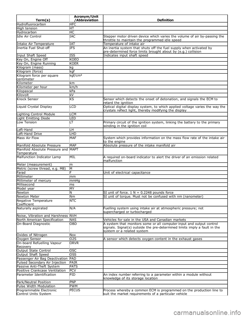
Hydrofluorocarbon HFC High tension HT Hydrocarbon HC Idle Air Control IAC
Stepper motor driven device which varies the volume of air by-passing the
throttle to maintain the programmed idle speed Intake Air Temperature IAT Temperature of intake air Inertia Fuel Shut-off IFS
An inertia system that shuts off the fuel supply when activated by pre-determined force limits brought about by (e.g.) collision Input Shaft Speed ISS Indicates input shaft speed Key On, Engine Off KOEO Key On, Engine Running KOER Kilogram (mass) kg Kilogram (force) kgf Kilogram force per square
centimeter kgf/cm²
Kilometer km Kilometer per hour km/h Kilopascal kPa Kilovolt kV Knock Sensor KS
Sensor which detects the onset of detonation, and signals the ECM to
retard the ignition Liquid Crystal Display LCD
Optical digital display system, to which applied voltage varies the way the crystals reflect light, thereby modifying the display Lighting Control Module LCM Light Emitting Diode LED Low Tension LT
Primary circuit of the ignition system, linking the battery to the primary winding in the ignition coil Left-Hand LH Left-Hand Drive LHD Mass Air Flow MAF
System which provides information on the mass flow rate of the intake air
to the engine Manifold Absolute Pressure MAP Absolute pressure of the intake manifold air Manifold Absolute Pressure and Temperature MAPT
Malfunction Indicator Lamp MIL
A required on-board indicator to alert the driver of an emission related
malfunction Meter (measurement) m Metric (screw thread, e.g. M8) M Farad F Unit of electrical capacitance Millimeter mm Millimeter of mercury mmHg Millisecond ms Model year MY Newton N SI unit of force. 1 N = 0.2248 pounds force Newton Meter Nm SI unit of torque. Must not be confused with nm (nanometer) Negative Temperature
Coefficient NTC
Naturally aspirated N/A
Fuelling system using intake air at atmospheric pressure; not supercharged or turbocharged Noise, Vibration and Harshness NVH North American Specification NAS Vehicles for sale in the USA and Canadian markets On-Board Diagnostic OBD
A system that monitors some or all computer input and output control
signals. Signal(s) outside the pre-determined limits imply a fault in the system or a related system Oxides of Nitrogen Nox Oxygen Sensor O2S A sensor which detects oxygen content in the exhaust gases On-board Refuelling Vapour Recovery ORVR
Output State Control OSC Output Shaft Speed OSS Passenger Air Bag Deactivation PAD Pulsed Secondary Air Injection PAIR Passive Anti-Theft System PATS Positive Crankcase Ventilation PCV Parameter Identification PID
An index number referring to a parameter within a module without knowledge of its storage location Park/Neutral Position PNP Pulse Width Modulation PWM Programmable Electronic
Control Units System PECUS
Process whereby a common ECM is programmed on the production line to
suit the market requirements of a particular vehicle
Page 165 of 3039

DTC Description Possible Causes Action module/component B10AC-82 Cruise Control Switch - Alive / sequence counter incorrect / not updated
Cruise buttons alive counter is not
incrementing. Which suggests that
the LIN bus is faulty
Steering wheel module is not
connected
Steering wheel module failure
Refer to the electrical circuit
diagrams and check the speed
control switch circuit for open circuit,
short circuit to power, short circuit to
ground, disconnected
Refer to the electrical circuit
diagrams and check the LIN bus
between steering wheel module and
the CAN gateway
Check and install a new steering
wheel module as required. Refer to
the warranty policy and procedures
manual, or determine if any prior
approval programme is in operation,
prior to the installation of a new
module/component B10AC-83
Cruise Control Switch - Value
of signal protection
calculation incorrect
Cruise buttons checksum incorrect,
incorrect cruise switches fitted to
vehicle
Check and install new cruise
switches as required. Refer to the
warranty policy and procedures
manual, or determine if any prior
approval programme is in operation,
prior to the installation of a new
module/component B10AC-96
Cruise Control Switch -
Component internal failure
Speed control switch circuit, open
circuit, short circuit to power, short
circuit to ground, disconnected
Speed control switch failure
Steering wheel module failure
Check for related DTCs in other
central junction boxes
Refer to the electrical circuit
diagrams and check the speed
control switch circuit for open circuit,
short circuit to power, short circuit to
ground, disconnected
Check and install a new speed
control switch as required. Check and
install a new steering wheel module
as required. Refer to the warranty
policy and procedures manual, or
determine if any prior approval
programme is in operation, prior to
the installation of a new
module/component B10FF-68
Ignition Control - Event
information
Spark plug(s) fault
Wiring harness fault
Ignition coil(s) fault
Refer to repair manual and check
spark plug(s) for condition and
security. Replace any defective
components as required
Refer to electrical wiring diagrams
and check ignition coil circuit for
intermittent open circuit, short
circuit to power, short circuit to
ground
Check and install a new coil(s) as
required. Refer to the warranty policy
and procedures manual, or determine
if any prior approval programme is in
operation, prior to the installation of
a new module/component B11DB-01
Battery Monitoring Module -
General electrical failure
NOTE: - Circuit BATTERY -
Charging system fault Battery
monitoring signal line
circuit fault
Vehicle battery fault
Refer to electrical wiring diagrams
and check charging system for faults.
Perform any repairs required
Refer to the electrical wiring
diagrams and check the battery
monitoring system module circuit for
open circuit, short circuit to ground,
short circuit to power
Refer to the workshop manual and
the battery care manual, inspect the
vehicle battery and ensure it is fully
charged and serviceable before
performing further tests
Page 839 of 3039
Published: 09-Apr-2014
Engine System - General Information - Cylinder Compression Test V8 S/C 5.0L
Petrol
General Procedures
Check
CAUTION: Before disconnecting or removing components, make sure the area around the joint faces and connections are
clean. Plug open connections to prevent contamination.
NOTES:
Removal steps in this procedure may contain installation details.
Some variation in the illustrations may occur, but the essential information is always correct.
The vehicle battery must be in good condition and fully charged before carrying out this procedure.
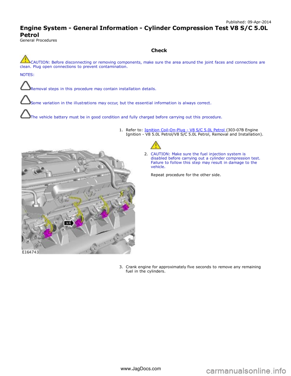
1. Refer to: Ignition Coil-On-Plug - V8 S/C 5.0L Petrol (303-07B Engine Ignition - V8 5.0L Petrol/V8 S/C 5.0L Petrol, Removal and Installation).
2. CAUTION: Make sure the fuel injection system is
disabled before carrying out a cylinder compression test.
Failure to follow this step may result in damage to the
vehicle.
Repeat procedure for the other side.
3. Crank engine for approximately five seconds to remove any remaining
fuel in the cylinders. www.JagDocs.com
Page 845 of 3039

Item Specification Camshaft journal maximum run out limit (mm) Camshaft journals to end journals 0.03 Camshaft journals to adjacent journals 0.015 Camshaft journal maximum out of round (mm) - all journals 0.005 Torque Specification
NOTE: A = Refer to procedure for correct torque sequence.
Description Nm lb-ft lb-in Engine cover mounting bolts 10 7 - Accessory drive belt tensioner retaining bolt 40 30 - Supercharger belt idler/tensioner bracket retaining bolts 25 18 - Secondary drive belt idler retaining bolts 40 30 - Power steering pump pulley retaining bolts 25 18 - Power steering pump retaining bolts 25 18 - Power steering pump bracket to engine retaining bolts 25 18 - Generator retaining bolts 48 35 - Starter motor retaining bolts 48 35 - Air conditioning compressor retaining bolts 25 18 - Engine mounting to engine mounting bracket retaining nuts 48 35 - Engine mounting to subframe retaining nuts 63 46 - Engine mounting bracket to engine retaining bolts 48 35 - Crankshaft damper pulley retaining LH threaded bolt 200 + 270° 148 + 180° - Flexplate retaining bolts 45 + 90° 33 + 90° - Exhaust manifold heat shield retaining bolts A - - Exhaust manifold retaining bolts A - - Engine wiring harness bracket retaining bolts 10 7 - Coolant outlet pipe 10 7 - Intercooler retaining bolts 25 18 - Intake manifold retaining bolts 25 18 - Oil Cooler retaining bolts 13 10 - Knock sensor (KS) retaining bolt 20 14 - Ignition coil retaining bolts 8 - 71 Spark plugs 20 15 - Fuel rail retaining bolts A - - High pressure fuel pipe retaining bolts A - - High pressure fuel pump retaining bolts 12 9 - Oil filter housing assembly retaining bolts 12 9 - Oil filter cap 28 21 - Lifting eye bolts 25 + 90° 18 + 90° - Manifold absolute pressure and temperature (MAPT) sensor sensor retaining bolts 5 - 44 Coolant pump retaining bolts 12 9 - Variable valve timing (VVT) oil control solenoid retaining bolts 10 7 - Camshaft position (CMP) sensor retaining bolts 10 7 - Camshaft cover retaining bolts 13 10 - Front upper timing cover retaining bolts 12 9 - Front lower timing cover retaining bolts A - - Engine rear cover retaining bolts A - - VVT to camshaft retaining bolts 32 24 - Camshaft bearing caps retaining bolts 11 8 - Primary timing chain fixed guide retaining bolts 12 9 - Primary timing chain tensioner retaining bolts 12 9 - Primary timing chain tensioner guide blade retaining bolts 25 18 - Auxiliary chain tensioner guide retaining bolts 21 15 - Auxiliary chain fixed guide retaining bolt 12 9 - Oil pump sprocket retaining bolt 21 15 - Cylinder head retaining bolts A - - Engine oil level (EOL) sensor retaining bolt 12 9 - Oil pan to oil sump body retaining bolts 12 9 - Oil sump body to engine retaining bolts 25 18 - Oil pan drain plug 23 17 - Oil transfer tube to Oil pan body retaining bolts 11 8 - Oil pump to engine block retaining bolts 25 18 - Pick-up pipe to oil pump retaining bolts 12 9 - Windage tray retaining bolts 25 18 - Piston cooling jet retaining bolts 12 9 - Engine block coolant draining plug 50 37 - Connecting Rod bolts Stage 1 10 7 - Stage 2 50 37 -
Page 1177 of 3039
Fuel Charging and Controls - V8 S/C 5.0L Petrol -
WARNINGS: Published: 11-May-2011
Do not smoke or carry lighted tobacco or open flame of any type when working on or near any fuel related components.
Highly flammable vapors are always present and may ignite. Failure to follow these instructions may result in personal injury.
Before any work is carried out on the fuel system, ground the vehicle to earth and maintain the ground connection until
the work is complete.
CAUTION: Before disconnecting or removing components, make sure the area around the joint faces and connections are
clean. Plug open connections to prevent contamination.
NOTE: Tighten the fuel rail high pressure fuel pump fuel line unions and fuel rail crossover pipe unions as it is instructed
in service manual.
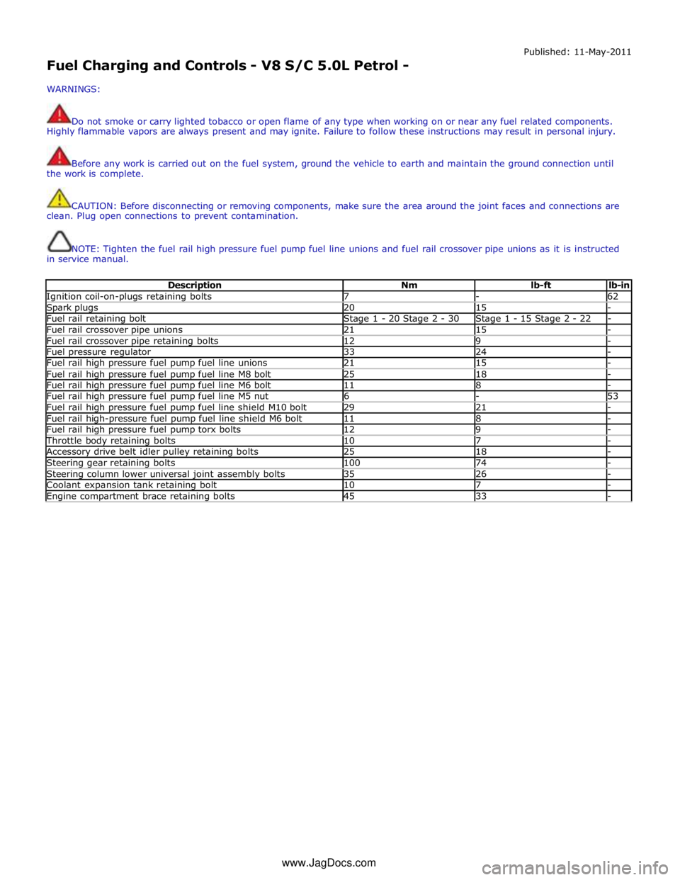
Description Nm lb-ft lb-in Ignition coil-on-plugs retaining bolts 7 - 62 Spark plugs 20 15 - Fuel rail retaining bolt Stage 1 - 20 Stage 2 - 30 Stage 1 - 15 Stage 2 - 22 - Fuel rail crossover pipe unions 21 15 - Fuel rail crossover pipe retaining bolts 12 9 - Fuel pressure regulator 33 24 - Fuel rail high pressure fuel pump fuel line unions 21 15 - Fuel rail high pressure fuel pump fuel line M8 bolt 25 18 - Fuel rail high pressure fuel pump fuel line M6 bolt 11 8 - Fuel rail high pressure fuel pump fuel line M5 nut 6 - 53 Fuel rail high pressure fuel pump fuel line shield M10 bolt 29 21 - Fuel rail high-pressure fuel pump fuel line shield M6 bolt 11 8 - Fuel rail high pressure fuel pump torx bolts 12 9 - Throttle body retaining bolts 10 7 - Accessory drive belt idler pulley retaining bolts 25 18 - Steering gear retaining bolts 100 74 - Steering column lower universal joint assembly bolts 35 26 - Coolant expansion tank retaining bolt 10 7 - Engine compartment brace retaining bolts 45 33 - www.JagDocs.com
Page 1181 of 3039
to deliver the correct mass of fuel to the combustion chambers.
LOW AND HIGH PRESSURE FUEL LINES Component Description
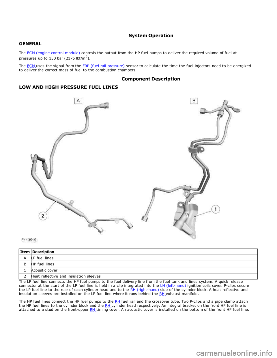
Item Description A LP fuel lines B HP fuel lines 1 Acoustic cover 2 Heat reflective and insulation sleeves The LP fuel line connects the HP fuel pumps to the fuel delivery line from the fuel tank and lines system. A quick release
connector at the start of the LP fuel line is held in a clip integrated into the LH (left-hand) ignition coils cover. P-clips secure
the LP fuel line to the rear of each cylinder head and to the RH (right-hand) side of the cylinder block. A heat reflective and
insulation sleeves are installed on the LP fuel line where it runs behind the RH exhaust manifold.
The HP fuel lines connect the HP fuel pumps to the RH fuel rail and the crossover tube. Two P-clips and a pipe clamp attach the HP fuel lines to the cylinder block and the RH cylinder head respectively. An integral bracket on the front HP fuel line is attached to a stud on the front-upper RH timing cover. An acoustic cover is installed on the bottom of the front HP fuel line.
Page 1270 of 3039

Firing order 1:2:7:3:4:5:6:8 Spark plug type - Vehicles with supercharger ILKAR6C-10 Spark plug type - Vehicles without supercharger ILKAR6C-10
Description Nm lb-ft lb-in Spark plugs 20 15 - Ignition coil-on-plug retaining bolts 7 5 -
Page 1271 of 3039
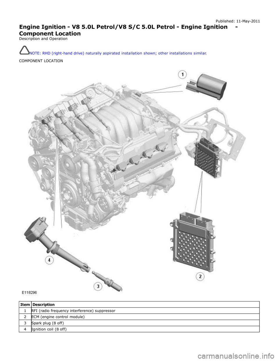
Published: 11-May-2011
Engine Ignition - V8 5.0L Petrol/V8 S/C 5.0L Petrol - Engine Ignition - Component Location
Description and Operation
NOTE: RHD (right-hand drive) naturally aspirated installation shown; other installations similar.
COMPONENT LOCATION
Item Description 1 RFI (radio frequency interference) suppressor 2 ECM (engine control module) 3 Spark plug (8 off) 4 Ignition coil (8 off)
Page 1272 of 3039

Published: 11-May-2011
Engine Ignition - V8 5.0L Petrol/V8 S/C 5.0L Petrol - Engine Ignition - Overview
Description and Operation
OVERVIEW
The engine ignition system is a coil-on-plug, single spark system controlled by the ECM (engine control module). An iridium
tipped spark plug is installed in each combustion chamber, between the inlet and exhaust valves, and an ignition coil is
installed on each spark plug. A RFI (radio frequency interference) suppressor is connected to the power feed to the ignition
coils.