ignition coil JAGUAR XFR 2010 1.G User Guide
[x] Cancel search | Manufacturer: JAGUAR, Model Year: 2010, Model line: XFR, Model: JAGUAR XFR 2010 1.GPages: 3039, PDF Size: 58.49 MB
Page 1273 of 3039
Published: 11-May-2011
Engine Ignition - V8 5.0L Petrol/V8 S/C 5.0L Petrol - Engine Ignition - System Operation and Component Description
Description and Operation
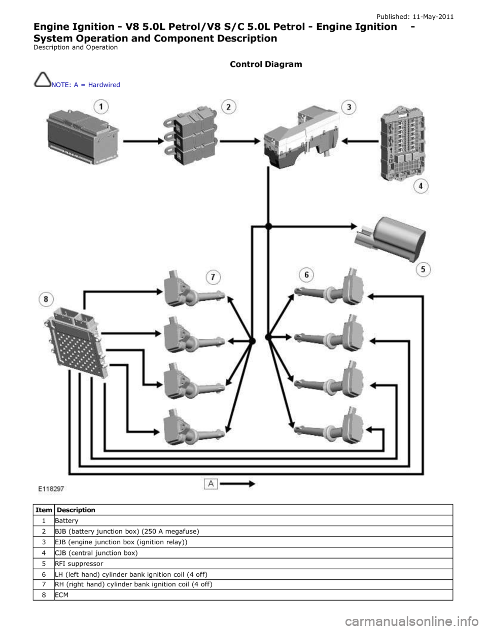
Control Diagram
NOTE: A = Hardwired
Item Description 1 Battery 2 BJB (battery junction box) (250 A megafuse) 3 EJB (engine junction box (ignition relay)) 4 CJB (central junction box) 5 RFI suppressor 6 LH (left hand) cylinder bank ignition coil (4 off) 7 RH (right hand) cylinder bank ignition coil (4 off) 8 ECM
Page 1274 of 3039
GENERAL System Operation
The ignition coils are supplied with electrical power from the battery via a 250 A megafuse in the BJB (battery junction box)
and the ignition relay in the EJB (engine junction box). The control signal for the ignition relay is supplied by the CJB (central
junction box).
The ECM (engine control module) sends a separate signal to each ignition coil to trigger the power stage switching. The ECM calculates the dwell time from the battery voltage and engine speed, to ensure a constant energy level is produced in the
secondary coil each time the power stage is switched. This ensures sufficient spark energy is available without excessive
primary current flow, which avoids overheating and damage to the ignition coils.
The ECM calculates the ignition timing for individual cylinders from: Engine speed
Camshaft position
Engine load
Engine temperature
The knock control function
The shift control function
The idle speed control function.
IGNITION COILS Component Description
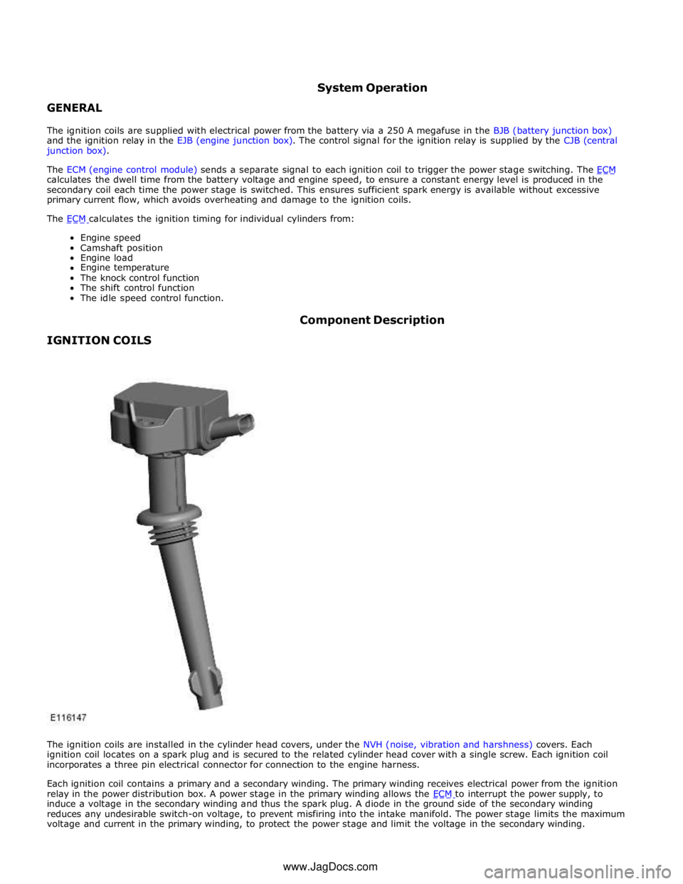
The ignition coils are installed in the cylinder head covers, under the NVH (noise, vibration and harshness) covers. Each
ignition coil locates on a spark plug and is secured to the related cylinder head cover with a single screw. Each ignition coil
incorporates a three pin electrical connector for connection to the engine harness.
Each ignition coil contains a primary and a secondary winding. The primary winding receives electrical power from the ignition
relay in the power distribution box. A power stage in the primary winding allows the ECM to interrupt the power supply, to induce a voltage in the secondary winding and thus the spark plug. A diode in the ground side of the secondary winding
reduces any undesirable switch-on voltage, to prevent misfiring into the intake manifold. The power stage limits the maximum
voltage and current in the primary winding, to protect the power stage and limit the voltage in the secondary winding. www.JagDocs.com
Page 1276 of 3039
Published: 11-May-2011
Engine Ignition - V8 5.0L Petrol/V8 S/C 5.0L Petrol - Engine Ignition
Diagnosis and Testing
Principles of Operation
For a detailed description of the engine ignition system and operation, refer to the relevant Description and Operation section
of the workshop manual. REFER to: (303-07B Engine Ignition - V8 5.0L Petrol/V8 S/C 5.0L Petrol)
Engine Ignition (Description and Operation), Engine Ignition (Description and Operation), Engine Ignition (Description and Operation).
Inspection and Verification
CAUTION: Diagnosis by substitution from a donor vehicle is NOT acceptable. Substitution of control modules does not
guarantee confirmation of a fault and may also cause additional faults in the vehicle being checked and/or the donor vehicle.
NOTE: Check and rectify basic faults before beginning diagnostic routines involving pinpoint tests.
1. Verify the customer concern.
2. Visually inspect for obvious signs of mechanical and electrical damage.
Visual Inspection
Mechanical Electrical
Engine oil level
Cooling system coolant level
Fuel level
Fuel contamination/grade/quality
Exhaust gas recirculation (EGR) valves
Fuses
Wiring harness
Loose or corroded electrical connectors
Ignition coils
Sensor(s)
Engine Control Module (ECM)
Transmission Control Module (TCM)
3. If an obvious cause for an observed or reported concern is found, correct the cause (if possible) before proceeding to
the next step.
4. If the cause is not visually evident, verify the symptom and refer to the Symptom Chart, alternatively check for
Diagnostic Trouble Codes (DTCs) and refer to the DTC Index.
Symptom Chart
Symptom Possible Causes Action Engine cranks, but does not
fire
Engine breather system
disconnected/restricted
Ignition system
Fuel system
Electronic engine control Ensure the engine breather system is free from restriction
and is correctly installed. Check for ignition system, fuel
system and electronic engine control DTCs and refer to the
relevant DTC Index Engine cranks and fires, but
will not start
Evaporative emissions purge
valve
Fuel pump
Spark plugs
HT short to ground (tracking)
check rubber boots for
cracks/damage
Ignition system Check for evaporative emissions, fuel system and ignition
system related DTCs and refer to the relevant DTC Index Difficult cold start
Engine coolant level/anti-
freeze content
Battery
Electronic engine controls
Exhaust Gas Recirculation
(EGR) valve stuck open
Fuel pump
Purge valve Check the engine coolant level and condition. Ensure the
battery is in a fully charged and serviceable condition.
Check for electronic engine controls, engine emissions, fuel
system and evaporative emissions system related DTCs
and refer to the relevant DTC Index
Page 1278 of 3039
Published: 11-May-2011
Engine Ignition - V8 5.0L Petrol/V8 S/C 5.0L Petrol - Ignition Coil-On-Plug V8 S/C 5.0L Petrol
Removal and Installation
Removal
NOTES:
Removal steps in this procedure may contain installation details.
Some variation in the illustrations may occur, but the essential information is always correct.
1. Refer to: Battery Disconnect and Connect (414-01, General Procedures).
2. Refer to: Engine Cover - 5.0L, Vehicles With: Supercharger (501-05,
Removal and Installation).
3. Refer to: Secondary Bulkhead Panel RH - 5.0L/3.0L Diesel (501-02,
Removal and Installation).
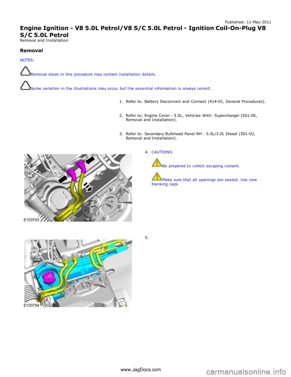
4. CAUTIONS:
Be prepared to collect escaping coolant.
Make sure that all openings are sealed. Use new
blanking caps.
5. www.JagDocs.com
Page 1369 of 3039

Published: 16-Sep-2013
Electronic Engine Controls - V8 S/C 5.0L Petrol - Electronic Engine Controls
Diagnosis and Testing
Principle of Operation
For a detailed description of electronic engine controls, refer to the relevant Description and Operation section of the workshop
manual. REFER to: (303-14D Electronic Engine Controls - V8 S/C 5.0L Petrol)
Electronic Engine Controls (Description and Operation), Electronic Engine Controls (Description and Operation), Electronic Engine Controls (Description and Operation).
Inspection and Verification
1. Verify the customer concern.
2. Visually inspect for obvious signs of damage and system integrity.
Visual Inspection
Mechanical Electrical
Engine oil level and condition
Cooling system coolant level
Fuel level
Fuel contamination/grade/quality
Throttle body
Front End Accessory Drive (FEAD) belt
Air cleaner condition
Fuses
Wiring harness
Electrical connector(s)
Sensor(s)
Engine Control Module
Transmission Control Module
3. If an obvious cause for an observed or reported concern is found, correct the cause (if possible) before proceeding to
the next step.
4. If the cause is not visually evident, verify the customer concern and refer to the Symptom Chart below, alternatively,
check for Diagnostic Trouble Codes (DTCs) and refer to the DTC Index.
Symptom Chart
Symptom Possible Cause Action Engine non-start Engine does not crank
Security system /Immobilizer
engaged
Engine in shut-down mode
ECM relay
Battery
Starting system
Engine seized
Check that the security system is disarmed
Read DTCs and refer to DTC Index in this
section for ECM relay tests
Ensure the battery is in fully charged and
serviceable condition
For starting system tests refer to the
relevant section of the workshop manual
For engine system tests refer to the relevant
section of the workshop manual Engine cranks, but does not fire
Engine breather system
disconnected/restricted
Ignition system
Fuel system
Electronic engine controls
Ensure the engine breather system is free
from restriction and is correctly installed
For ignition system tests refer to the
relevant section of the workshop manual
For fuel system tests refer to the relevant
section of the workshop manual
Read DTCs and refer to DTC Index in this
section for electronic engine control tests Engine cranks and fires, but will not
start
Evaporative emissions purge
valve
Fuel pump
Spark plugs
Ignition coil failure(s)
For purge valve tests refer to the relevant
section of the workshop manual
For fuel system tests refer to the relevant
section of the workshop manual
For ignition system tests refer to the
relevant section of the workshop manual Difficult to start Difficult cold start
Check engine coolant
level/anti-freeze content
Battery
Electronic engine controls
Exhaust gas recirculation
Check the engine coolant level and
condition. Refer to the relevant sections of
the workshop manual
Ensure the battery is in a fully charged and
serviceable condition. Refer to the battery
Page 1373 of 3039

DTC Description Possible Causes Action B10AC-81
Cruise Control Switch -
invalid serial data received
The Engine Control Module
(ECM) has received an invalid
command from the steering
wheel switch pack Clear the DTC and press all the steering wheel
switches, re-check for DTCs. Refer to the
electrical circuit diagrams and check the Cruise
control switch circuit for open circuit, short to
power, short to ground, disconnected. Check
and install a new Steering Wheel Module (SWM) as required. B10AC-82 Cruise Control Switch - alive / sequence counter incorrect / not updated
Cruise Buttons alive counter is
not incrementing. Which
suggests that the LIN bus is
faulty
Steering Wheel Module (SWM) is
not connected
Steering Wheel Module (SWM)
failure Refer to the electrical circuit diagrams and
check the Cruise control switch circuit for open
circuit, short to power, short to ground,
disconnected. Check and install a new Steering
Wheel Module (SWM) as required. B10AC-83
Cruise Control Switch - value
of signal protection
calculation incorrect
Cruise buttons checksum
incorrect, incorrect cruise
switches fitted to vehicle Check and install new cruise switches as
required. B10AC-96
Cruise Control Switch -
component internal failure
Cruise control switch circuit,
open circuit, short to power,
short to ground, disconnected
Cruise Control Switch failure
Steering Wheel Module (SWM)
failure Check for related DTCs in other Central
Junction Box (CJB)s. Refer to the electrical
circuit diagrams and check the Cruise control
switch circuit for open circuit, short to power,
short to ground, disconnected. Check and
install a new cruise control switch as required.
Check and install a new Steering Wheel
Module (SWM) as required. B10FF-68
Ignition Control - Event
information
Spark plug(s) fault
Wiring harness fault
Ignition coil(s) fault Refer to repair manual and check spark plug(s)
for condition and security. Replace any
defective components as required. Refer to
electrical wiring diagrams and check ignition
coil circuit for intermittent open circuit, short
to power, short to ground. Check and install a
new coil(s) as required. B11DB-01
Battery Monitoring Module -
General Electrical Failure
Charging system fault Battery
monitoring signal line
circuit fault
Vehicle battery fault Refer to electrical wiring diagrams and check
charging system for faults. Perform any repairs
required. Refer to the electrical wiring
diagrams and check the Battery Monitoring
System (BMS) module circuit for open circuit,
short to ground, short to power. Refer to the
battery care manual and check and install a
new battery. B11DB-87
Battery Monitoring Module -
missing message
Battery signal line circuit fault Refer to the electrical wiring diagrams and
check the Battery Monitoring System (BMS)
module circuit for open circuit, short to ground,
short to power. B1206-68
Crash Occurred - event
information
Engine control Module (ECM) has
detected the vehicle has crashed
- event information DTC only Refer to the electrical circuit diagrams and
check the Engine Control Module (ECM) to
Restraints Control Module (RCM) circuit for
short to ground, short to power, open circuit.
Repair circuit as required, clear DTC and retest
system to confirm repair. C0031-00
Left Front Wheel Speed
Sensor - No sub type
information
Invalid data received from
Anti-lock Braking System (ABS)
module - left front wheel speed
signal fault Check Anti-lock Braking System (ABS) module
for related DTCs and refer to relevant DTC
Index. C0034-00
Right Front Wheel Speed
Sensor - No sub type
information
Invalid data received from
Anti-lock Braking System (ABS)
module - right front wheel speed
signal fault Check Anti-lock Braking System (ABS) module
for related DTCs and refer to relevant DTC
Index. C0037-00
Left Rear Wheel Speed
Sensor - No sub type
information
Invalid data received from
Anti-lock Braking System (ABS)
module - left rear wheel speed
signal fault Check Anti-lock Braking System (ABS) module
for related DTCs and refer to relevant DTC
Index. C003A-00
Right Rear Wheel Speed
Sensor - No sub type
information
Invalid data received from
Anti-lock Braking System (ABS)
module - right rear wheel speed
signal fault Check Anti-lock Braking System (ABS) module
for related DTCs and refer to relevant DTC
Index.
Page 1710 of 3039
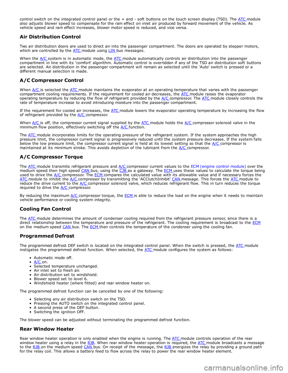
control switch on the integrated control panel or the + and - soft buttons on the touch screen display (TSD). The ATC module also adjusts blower speed to compensate for the ram effect on inlet air produced by forward movement of the vehicle. As
vehicle speed and ram effect increases, blower motor speed is reduced, and vice versa.
Air Distribution Control
Two air distribution doors are used to direct air into the passenger compartment. The doors are operated by stepper motors,
which are controlled by the ATC module using LIN bus messages.
When the A/C system is in automatic mode, the ATC module automatically controls air distribution into the passenger compartment in line with its 'comfort' algorithm. Automatic control is overridden if any of the TSD air distribution soft buttons
are selected. Air distribution in the passenger compartment will remain as selected until the 'Auto' switch is pressed or a
different manual selection is made.
A/C Compressor Control
When A/C is selected the ATC module maintains the evaporator at an operating temperature that varies with the passenger compartment cooling requirements. If the requirement for cooled air decreases, the ATC module raises the evaporator operating temperature by reducing the flow of refrigerant provided by the A/C compressor. The ATC module closely controls the rate of temperature increase to avoid introducing moisture into the passenger compartment.
If the requirement for cooled air increases, the ATC module lowers the evaporator operating temperature by increasing the flow of refrigerant provided by the A/C compressor.
When A/C is off, the compressor current signal supplied by the ATC module holds the A/C compressor solenoid valve in the minimum flow position, effectively switching off the A/C function.
The ATC module incorporates limits for the operating pressure of the refrigerant system. If the system approaches the high pressure limit, the compressor current signal is progressively reduced until the system pressure decreases. If the system falls
below the low pressure limit, the compressor current signal is held at its lowest setting so that the A/C compressor is maintained at its minimum stroke. This avoids depletion of the lubricant from the A/C compressor.
A/C Compressor Torque
The ATC module transmits refrigerant pressure and A/C compressor current values to the ECM (engine control module) over the medium speed then high speed CAN bus, using the CJB as a gateway. The ECM uses these values to calculate the torque being used to drive the A/C compressor. The ECM compares the calculated value with its allowable value and if necessary forces the ATC module to inhibit the A/C compressor by transmitting the 'ACClutchInhibit' CAN message. This forces the ATC module to reduce the drive current to the A/C compressor solenoid valve, which reduces refrigerant flow. This in turn reduces the torque required to drive the A/C compressor.
By reducing the maximum A/C compressor torque, the ECM is able to reduce the load on the engine when it needs to maintain vehicle performance or cooling system integrity.
Cooling Fan Control
The ATC module determines the amount of condenser cooling required from the refrigerant pressure sensor, since there is a direct relationship between the temperature and pressure of the refrigerant. The cooling requirement is broadcast to the ECM on the medium speed CAN bus. The ECM then controls the temperature of the condenser using the cooling fan.
Programmed Defrost
The programmed defrost DEF switch is located on the integrated control panel. When the switch is pressed, the ATC module instigates the programmed defrost function. When selected, the ATC module configures the system as follows:
Automatic mode off.
A/C on. Selected temperature unchanged.
Air inlet set to fresh air.
Air distribution set to windshield.
Blower speed set to level 6.
Windshield heater (where fitted) and rear window heater on.
The programmed defrost function can be cancelled by one of the following:
Selecting any air distribution switch on the TSD.
Pressing the AUTO switch on the integrated control panel.
A second press of the DEF button.
Switching the ignition OFF.
The blower speed can be adjusted without terminating the programmed defrost function.
Rear Window Heater
Rear window heater operation is only enabled when the engine is running. The ATC module controls operation of the rear window heater using a relay in the RJB. When rear window heater operation is required, the ATC module broadcasts a message to the RJB on the medium speed CAN bus. On receipt of the message, the RJB energizes the relay by providing a ground path for the relay coil. This allows a battery feed to flow across the relay to power the rear window heater element.
Page 2146 of 3039
Check the Starter Relay circuit.
NOTE: On petrol engine variants, due to Smart Start, both sides of Relay Coil are switched directly from ECM (If
conditions correct). On diesel engine variants the low side only is switched directly from the ECM.
Check that the Steering Column Lock correctly operates and the steering wheel can turn freely.
Check that the High Speed CAN network is not malfunctioning, i.e. the CAN circuit is open or short circuit. This would mean
that the instrument cluster and ECM would be unable to communicate resulting in no Challenge being performed to enable the
ECM. This would be supported by LED Flash Code 24, see PATS Fault Code Table.
Also check the CAN network between the ABS module and the CJB. The CJB uses the CAN_BrakePressureTMC signal to
determine if the brake pedal has been pressed in order to allow an engine crank. The CJB uses a value of 0x05, if the CJB sees
a value less than this, it will not enable the Crank Request Output.
Engine cranks but will not start
If the Engine is cranking it means that the ECM has passed the authorisation required with the Instrument Cluster. If this
authorisation failed, the ECM would not engage the starter relay. This could be confirmed by verifying the PATS LED prove out
(illuminated solid for 3 seconds) or by reading DTCs from the instrument cluster and ECM.
In this case, the fuel pump circuit should be verified. The Fuel Pump Delivery Module (FPDM), which is supplied via the RJB
(authentication required with the instrument cluster) and controlled by the ECM, supplies the fuel pump.
In all cases of suspected non-start issues, the most logical failure modes should be eliminated first. i.e.
1. Check all relevant supplies and grounds to the relevant modules listed herein.
2. Note any unusual behaviour from other systems/functionality.
3. Note any functions that are not operating as expected.
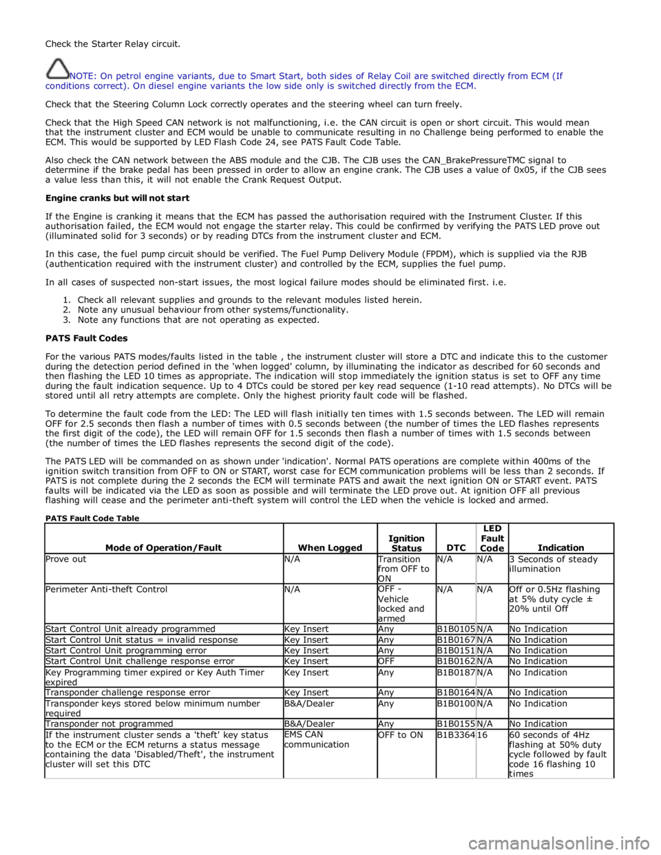
PATS Fault Codes
For the various PATS modes/faults listed in the table , the instrument cluster will store a DTC and indicate this to the customer
during the detection period defined in the 'when logged' column, by illuminating the indicator as described for 60 seconds and
then flashing the LED 10 times as appropriate. The indication will stop immediately the ignition status is set to OFF any time
during the fault indication sequence. Up to 4 DTCs could be stored per key read sequence (1-10 read attempts). No DTCs will be
stored until all retry attempts are complete. Only the highest priority fault code will be flashed.
To determine the fault code from the LED: The LED will flash initially ten times with 1.5 seconds between. The LED will remain
OFF for 2.5 seconds then flash a number of times with 0.5 seconds between (the number of times the LED flashes represents
the first digit of the code), the LED will remain OFF for 1.5 seconds then flash a number of times with 1.5 seconds between
(the number of times the LED flashes represents the second digit of the code).
The PATS LED will be commanded on as shown under 'indication'. Normal PATS operations are complete within 400ms of the
ignition switch transition from OFF to ON or START, worst case for ECM communication problems will be less than 2 seconds. If
PATS is not complete during the 2 seconds the ECM will terminate PATS and await the next ignition ON or START event. PATS
faults will be indicated via the LED as soon as possible and will terminate the LED prove out. At ignition OFF all previous
flashing will cease and the perimeter anti-theft system will control the LED when the vehicle is locked and armed.
PATS Fault Code Table
Mode of Operation/Fault
When Logged
Ignition
Status
DTC LED
Fault
Code
Indication Prove out N/A Transition
from OFF to
ON N/A N/A
3 Seconds of steady
illumination Perimeter Anti-theft Control N/A OFF -
Vehicle
locked and
armed N/A N/A
Off or 0.5Hz flashing
at 5% duty cycle ±
20% until Off Start Control Unit already programmed Key Insert Any B1B0105 N/A No Indication Start Control Unit status = invalid response Key Insert Any B1B0167 N/A No Indication Start Control Unit programming error Key Insert Any B1B0151 N/A No Indication Start Control Unit challenge response error Key Insert OFF B1B0162 N/A No Indication Key Programming timer expired or Key Auth Timer expired Key Insert Any B1B0187 N/A No Indication Transponder challenge response error Key Insert Any B1B0164 N/A No Indication Transponder keys stored below minimum number required B&A/Dealer Any B1B0100 N/A No Indication Transponder not programmed B&A/Dealer Any B1B0155 N/A No Indication If the instrument cluster sends a 'theft' key status
to the ECM or the ECM returns a status message
containing the data 'Disabled/Theft', the instrument
cluster will set this DTC EMS CAN
communication OFF to ON B1B3364 16
60 seconds of 4Hz
flashing at 50% duty
cycle followed by fault
code 16 flashing 10
times