Can bus JAGUAR XFR 2010 1.G Workshop Manual
[x] Cancel search | Manufacturer: JAGUAR, Model Year: 2010, Model line: XFR, Model: JAGUAR XFR 2010 1.GPages: 3039, PDF Size: 58.49 MB
Page 1845 of 3039
3 RJB 4 Entertainment system control module 5 Touch Screen Display (TSD) 6 Parking aid camera
PARKING AID System Operation
Two levels of parking aid system can be fitted; a rear only system or a front and rear system.
The parking aid module receives and ignition power mode 6 supply from the RJB. The parking aid module is connected to the entertainment system control module by the medium speed CAN (controller area
network) bus and the Media Orientated System Transport (MOST). The entertainment system is used by the parking aid system
to provide the driver with an audible warning. If an obstacle is sensed by the rear parking aid sensors, the rear audio system
speakers will sound. If an obstacle is sensed by the front parking aid sensors (if fitted), the front audio system speakers will
sound.
The parking aid system operates using ultrasonic signals which are transmitted by the sensors. The reflected echo from this
output is received by the sensors and used by the parking aid module to calculate the distance from an object.
When the parking aid module activates the system, the switch LED (light emitting diode) is illuminated to indicate that the
system is operating. The parking aid module then processes signals received from the sensors to determine if there is an
object with the detection range of the sensors. A parking aid screen is automatically displayed in the Touch Screen Display. If
the vehicle has a parking aid camera fitted, the camera display is automatically displayed in the TSD in preference to the
parking aid alert display. To view the parking aid sensor display, a single touch of the TSD screen will remove the camera
image display and show the parking aid alert display.
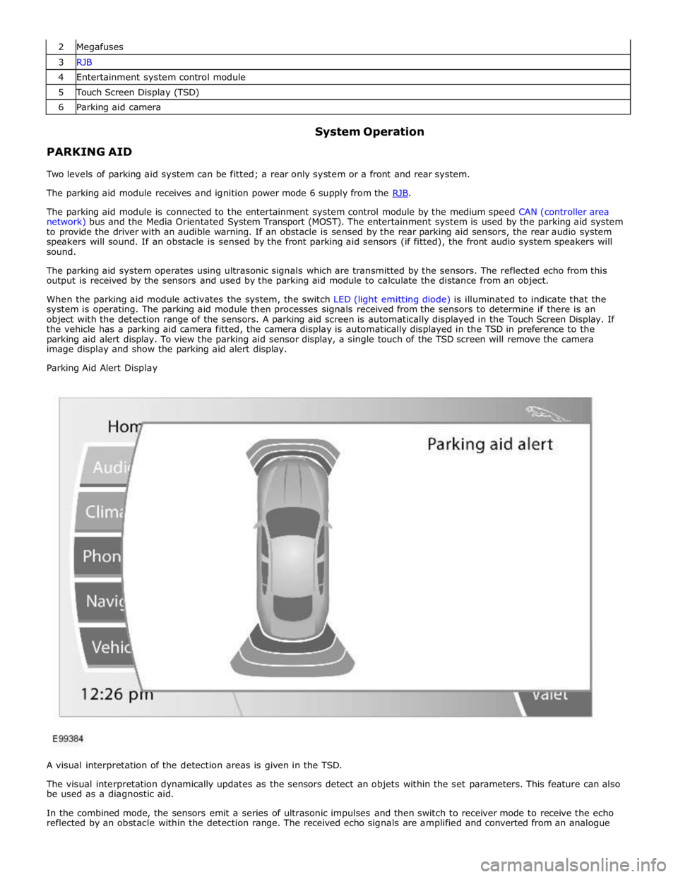
Parking Aid Alert Display
A visual interpretation of the detection areas is given in the TSD.
The visual interpretation dynamically updates as the sensors detect an objets within the set parameters. This feature can also
be used as a diagnostic aid.
In the combined mode, the sensors emit a series of ultrasonic impulses and then switch to receiver mode to receive the echo
reflected by an obstacle within the detection range. The received echo signals are amplified and converted from an analogue
Page 1846 of 3039
signal to a digital signal by the sensor. The digital signal is passed to the parking aid module and compared with
pre-programmed data stored in an EEPROM (electrically erasable programmable read only memory) within the module. The
module receives this data via the signal line from the sensor and calculates the distance from the object using the elapsed
time between the transmitted and received impulse. The duration of the impulse duration is determined by the module, with
the sensor controlling the frequency of the impulse output.
In receiver mode, the sensor receives impulses that were emitted by adjacent sensors. The module uses this information to
precisely determine the position and distance of the object.
If no objects are detected there are no further warning tones. If an object is detected, repeated audible tones are emitted
from either the front or rear audio speakers as appropriate. The time delay between the tones decreases as the distance
between the object and the vehicle decreases, until at approximately 300 mm (12 inches), the audible tone becomes
continuous.
After the initial detection of an object, if there is no decrease in the distance between an object and the central sensors, the
time delay between the audible warnings remains constant. If an object is detected by one of the corner sensors only, the
audible warnings stop after approximately 5 seconds if there is no change in the distance between an object and the corner
sensor.
When approaching several objects within detection range, the control module recognises the distance from the vehicle to the
nearest object.
The PDC module will prioritise the objects detected, the nearest object detected will take priority and the corresponding audio
outputs will be emitted. For example if 2 objects are detected (one front one rear) the nearest detected object will take
priority and relevant audible tone will be heard.
If two objects are detected at equal distance (one front one rear) the audible tones will alternate between the front and rear
speakers.
If reverse (R) is the first gear selected after the ignition is switched on, both the front (if fitted) and rear parking aid sensors
will become operational. If a forward drive gear is subsequently selected, the front and rear parking aid sensors will remain
operational until vehicle speed increases above 16 km/h (10 mph), park (P) is selected or the PDC control switch is pressed.
If drive (D) is the first gear selected after the ignition is switched on the parking aid system will have to be activated by
pressing the PDC control switch.
NOTE: The PDC system can not be activated whilst the vehicle is in park (P).
The volume output of the parking aid audible tones can be adjusted by selecting the 'Vehicle Settings' menu and selecting
'Parking' from the menu on the TSD. The volume can be adjusted using the + or - selections on the TSD.
The system can detect when a trailer is connected to the vehicle by a message output on the medium speed CAN bus from the trailer module. When the parking aid module detects that a trailer is connected to the vehicle, the rear sensors are disabled to
prevent constant warnings due to the close proximity of the trailer.
NOTE: The ignition needs to be cycled once the trailer has been disconnected to activate the rear parking aid system.
Page 1847 of 3039
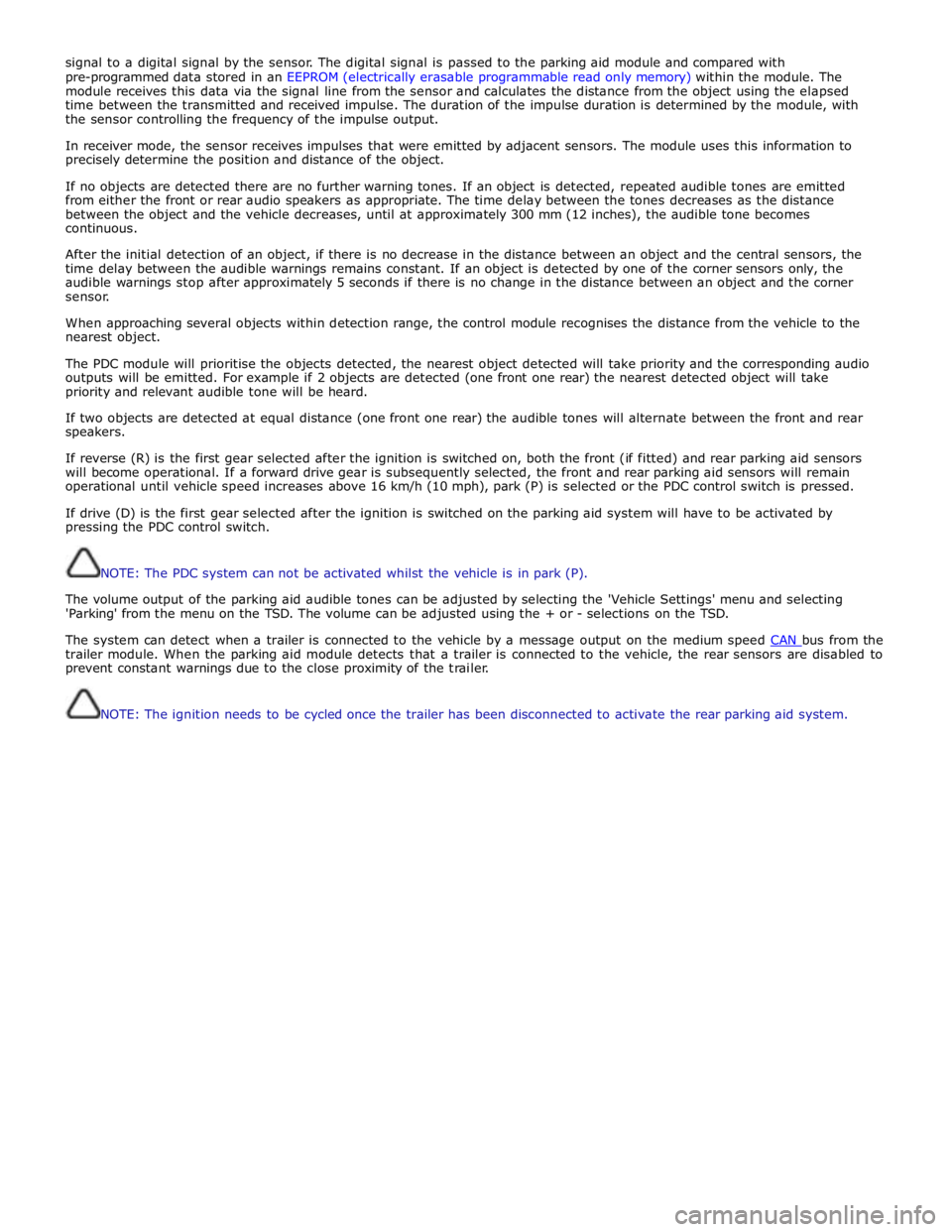
1 Rear/Front Outer Approximately 600 mm (24 inches) Approximately 300 mm (12 inches) 2 Rear Inner Approximately 1800 mm (71 inches) Approximately 300 mm (12 inches) 3 Front Inner Approximately 800 mm (31 inches) Approximately 300 mm (12 inches) PARKING AID CAMERA
The parking aid camera receives an ignition power mode 6 power supply from the RJB. It also has a LIN (local interconnect network) bus connection from the RJB which is not used at the moment but installed for a later enhancement of the parking aid camera.
A shielded co-axial cable connection between the camera and the Touch Screen Display (TSD) is used for the video image
transmission.
The camera receives power at all times when the ignition is in power mode 6. When reverse gear is selected, the RJB transmits a reverse selected signal on the medium speed CAN bus message to the entertainment system control module. This message is transferred on the MOST to the TSD which displays the parking aid camera video input from the camera in
preference to the parking aid alert screen.
If the driver does not require the camera image in the TSD, a single touch on the screen will revert the display to the parking
aid alert screen. The camera view can be reselected by pressing the 'Rear Camera' softkey on the TSD.
When reverse gear is deselected, the camera image remains on the TSD for 10 seconds after the transmission has been put
into drive 'D'. This is to prevent the TSD switching between screens if the vehicle is being manoeuvred into a parking space. If
the vehicle forward speed exceeds 16 km/h (10 mph) within the 10 second period, the camera image is removed from the TSD.
If the TSD display is switched off, the camera image will be automatically displayed when reverse gear is selected. When
reverse gear is deselected and the 10 second period has expired, the TSD will revert back to its switched off state.
PARKING AID
Parking Aid Module Component Description
The parking aid module is located on the LH side of the luggage compartment.
The parking aid module has three connectors which provide for power, ground and CAN bus connections, front parking aid sensors and rear parking aid sensors. The medium speed CAN bus connections provide for the receipt of the following Distance Calculation
www.JagDocs.com
Page 1848 of 3039
information from other systems:
ABS (anti-lock brake system) module - Road speed signal
TCM (transmission control module) - Reverse gear engaged signal
Trailer module - Trailer attached to vehicle
The module also outputs messages on the medium speed CAN bus which are received by the integrated audio module. The integrated audio module processes these messages and converts them into Media Orientated System Transport (MOST) signals
which are passed to the audio system power amplifier. These signals are then used by the power amplifier to emit the
applicable warning tones from the front or rear audio speakers when an object is detected by the front or rear parking aid
sensors. A warning tone can also be emitted to alert the driver to a fault in the parking aid system.
The control module has a diagnostic connection via the medium speed CAN bus to enable faults to be retrieved using the
Jaguar approved diagnostic equipment. Additionally an on-board diagnostic routine within the control module constantly
monitors the system and alerts the driver to a system fault by emitting a 3 second continuous tone through the rear audio
system speakers when the ignition is switched on. If front parking aid sensors are fitted, the control switch LED will also flash
6 times.
Parking Aid Sensors
Four ultrasonic sensors are located in the front (if fitted) and rear bumpers.
Each sensor has a three pin connector which mates with a bumper harness, which in turn is connected to the main body
harness. Three pins provide for power supply, ground and signal lines to and from the parking aid module.
The parking aid module controls the operation of each sensor using a digital output on the signal line. The module controls the
sensor in one of two modes; combined transmitter and receiver mode or receiver mode only.
Parking Aid Switch
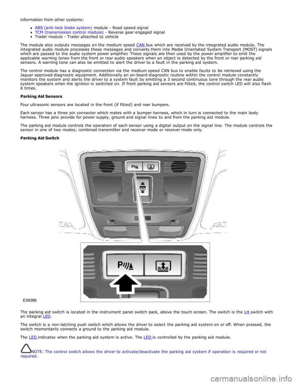
The parking aid switch is located in the instrument panel switch pack, above the touch screen. The switch is the LH switch with an integral LED.
The switch is a non-latching push switch which allows the driver to select the parking aid system on or off. When pressed, the
switch momentarily connects a ground to the parking aid module.
The LED indicates when the parking aid system is active. The LED is controlled by the parking aid module.
NOTE: The control switch allows the driver to activate/deactivate the parking aid system if operation is required or not
required.
Page 1849 of 3039
PARKING AID CAMERA
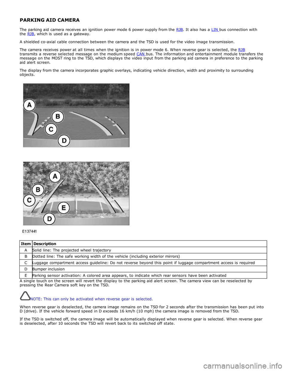
The parking aid camera receives an ignition power mode 6 power supply from the RJB. It also has a LIN bus connection with the RJB, which is used as a gateway. A shielded co-axial cable connection between the camera and the TSD is used for the video image transmission.
The camera receives power at all times when the ignition is in power mode 6. When reverse gear is selected, the RJB transmits a reverse selected message on the medium speed CAN bus. The information and entertainment module transfers the message on the MOST ring to the TSD, which displays the video input from the parking aid camera in preference to the parking
aid alert screen.
The display from the camera incorporates graphic overlays, indicating vehicle direction, width and proximity to surrounding
objects.
Item Description A Solid line: The projected wheel trajectory B Dotted line: The safe working width of the vehicle (including exterior mirrors) C Luggage compartment access guideline: Do not reverse beyond this point if luggage compartment access is required D Bumper inclusion E Parking sensor activation: A colored area appears, to indicate which rear sensors have been activated A single touch on the screen will revert the display to the parking aid alert screen. The camera view can be reselected by
pressing the Rear Camera soft key on the TSD.
NOTE: This can only be activated when reverse gear is selected.
When reverse gear is deselected, the camera image remains on the TSD for 2 seconds after the transmission has been put into
D (drive). If the vehicle forward speed in D exceeds 16 km/h (10 mph) the camera image is removed from the TSD.
If the TSD is switched off, the camera image will be automatically displayed when reverse gear is selected. When reverse gear
is deselected, after 10 seconds the TSD will revert back to its switched off state.
Page 1850 of 3039
Parking Aid - Parking Aid
Diagnosis and Testing
Principles of Operation Published: 24-Feb-2014
For a detailed description of the parking aid system, characteristics and limitations refer to the relevant description and
operation section in the workshop manual.
REFER to: Parking Aid (413-13 Parking Aid, Description and Operation).
Parking Aid System On-Board Self-Test
As part of the strategy of the system if any DTCs are detected, a long high-pitched tone approx 3 seconds will sound and the
parking aid switch (where fitted) indicator LED will flash 6 times at ignition on
If a fault is present when the parking aid system is activated then the parking aid switch (where fitted) status LED will
flash 6 times indicating an issue with front or rear parking aid sensors, wiring switch, parking aid control module or hard
wired sounders
The rear parking aid sounder/rear audio system will emit an error tone for approx 3 seconds at ignition on if a fault is
detected with the front or rear sensors, the switch, or if there is a controller area network (CAN) bus error
(Only applicable to vehicles fitted with front parking aid and a hard wired rear parking aid sounder). If there is a fault
with the rear parking aid sounder the error tone will come from the front parking aid sounder unit (integral with the
instrument cluster)
Audible and Visual Warnings when Parking Aid System is in Error State
Rear Parking Aid
System Fitted and
No Parking Aid
System Switch
Fitted
Rear Parking Aid System Fitted and Parking Aid System Switch Fitted
Front and Rear Parking Aid System Fitted with Parking Aid System Switch Fitted A long high-pitched
error tone will
sound at Ignition
On for approx 3
seconds
A long high-pitched error tone will sound at
ignition on for approx 3 seconds and the
parking aid switch indicator LED will flash 6
times at ignition on. Every time the parking
aid system is activated within the same
ignition cycle, parking aid switch indicator
LED will flash 6 times
A long high-pitched error tone will sound at
ignition on for approximately 3 seconds and
the parking aid switch indicator LED will flash 6
times at ignition on. Every time the parking aid
system is activated within the same ignition
cycle the parking aid switch indicator LED will
flash 6 times Inspection and Verification
CAUTIONS:
If the control module or a component is suspect and the vehicle remains under manufacturer warranty, refer to the
warranty policy and procedures manual (section B1.2), or determine if any prior approval programme is in operation, prior to
the installation of a new module/component.
Diagnosis by substitution from a donor vehicle is NOT acceptable. Substitution of control modules does not guarantee
confirmation of a fault, and may also cause additional faults in the vehicle being tested and/or the donor vehicle
Do not apply any grease based products to any parking aid system connector or pins
NOTE: Check DDW for open campaigns. Refer to the corresponding bulletins and SSMs which may be valid for the specific
customer complaint and carry out the recommendations as required.
1. Verify the customer concern
2. Visually inspect for obvious signs of mechanical or electrical damage
3. Ensure that the parking aid sensor face is clear of contamination that could affect the performance of the sensor
Visual Inspection
Mechanical Electrical
Parking aid sensor condition/damaged
Parking aid sensor installation and holder
Parking aid sensor alignment
Parking aid sensor contamination
Bumper cover(s)
Vehicle ride height
Non standard/non manufacturer approved accessories fitted
Battery
Fuse(s)
Relays
Wiring harness
Electrical connector(s)
Front parking aid sensor(s)
Rear parking aid sensor(s)
Parking aid switch and LED
Page 1879 of 3039

The dual battery system comprises the following components:
Dual Battery Module (DBM).
Dual Battery Junction Box (DBJB).
Gateway Module (GWM).
Primary battery.
Secondary battery.
The GWM hosts most of the software required to control the dual battery system and components. The GWM monitors the
components and can store fault related DTC's.
The GWM also controls the charging system software in conjunction with the ECM, RJB, CJB and ABS (anti-lock brake system) control module via the high speed and medium speed CAN (controller area network) bus. The GWM software will monitor the
status of the stop/start system and determine when a stop/start event can occur. It can also intervene to maintain vehicle
systems by keeping the engine running or initiating a restart due to, for example, climate control system requirements or
request for restart from the ECM. A brake pressure signal is received from the ABS control module which will indicate to the
GWM that an engine restart is required from driver operation of the foot brake.
The GWM contains the intelligent power management system and the BMS software. Monitoring of the primary battery
condition for stop/start is controlled by the GWM and the BMS control module.
Page 1880 of 3039
Published: 18-Jun-2014
Battery, Mounting and Cables - Battery and Cables - System Operation and
Component Description
Description and Operation
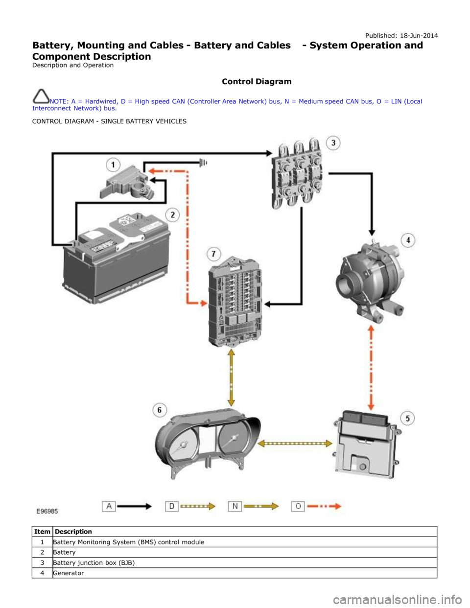
Control Diagram
NOTE: A = Hardwired, D = High speed CAN (Controller Area Network) bus, N = Medium speed CAN bus, O = LIN (Local
Interconnect Network) bus.
CONTROL DIAGRAM - SINGLE BATTERY VEHICLES
Item Description 1 Battery Monitoring System (BMS) control module 2 Battery 3 Battery junction box (BJB) 4 Generator
Page 1882 of 3039

11 Secondary battery 12 Dual Battery Junction Box (DBJB) 13 Rear Junction Box (RJB) 14 Megafuse 15 Battery Junction box (BJB) 16 Primary battery
System Operation BATTERY MONITORING SYSTEM - TD4 2.2L DIESEL VEHICLES ONLY
Periodically the battery monitoring system module will instigate a self-calibration routine. To self calibrate, the battery
monitoring system first charges the battery to its full condition.
NOTE: If the vehicle is only driven for short periods the charging process could take a number of days to complete.
Once the battery is fully charged, the battery monitoring system will discharge the battery to approximately 75% of its full
state of charge, but never lower than 12.2 V. The time taken to complete this part of the routine is dependent on the electrical
load on the vehicle.
When the second part of the routine has been successfully completed, the battery monitoring system will return the battery to
its optimum level of charge. The optimum level of charge will be between 12.6 V and 15 V, depending on battery condition,
temperature and loading.
The battery monitoring system module also monitors the battery condition with the engine switched off. If a low voltage
condition is detected the module can request the infotainment system is switched off to protect battery voltage. Once the
infotainment system has been switched off, the vehicle must be run for at least 5 minutes to charge the battery before the
infotainment system can be operated with the engine switched off.
BATTERY MONITORING SYSTEM - SINGLE AND DUAL BATTERY SYSTEM VEHICLES
When the ignition is off (power mode 0), the BMS control module records the primary battery state of charge and begins to
monitor the battery condition from this point.
If the battery state of charge falls by 7%, the BMS control module will monitor the primary battery for 5 minutes. If after the 5
minute monitoring period, the primary battery charge has continued to fall due to the quiescent drain current being too high,
the BMS control module will determine that some control modules are still 'awake'. The BMS control module sends a shutdown
message on the LIN (local interconnect network) bus to the GWM (Gateway Module). The GWM sends a CAN (controller area
network) bus message on both the medium and high speed networks to all control modules, requesting them to shutdown.
The BMS control module will monitor the primary battery state of charge for a further 5 minutes and determine if the primary
battery state of charge is still dropping. If a quiescent drain current continues, the primary battery state of charge will
continue to drop. If the state of charge falls to 12% of the initial monitoring value, the BMS control module determines that
one or more control modules are still awake and a failure to respond to the shutdown request may indicate an error state
within the control module(s).
BMS Low Battery Warning and Energy Management Messages
The BMS continuously monitors the condition of the primary vehicle battery. If excessive battery discharge occurs, the system
will begin to shut down non-essential electrical systems in order to protect the battery.
If the BMS calculates that battery condition is not within set parameters, there are 3 messages that can be displayed, 2 on the
touch screen and 1 on the message center. These inform the user that the battery is either at a low level of charge or the
engine-off power consumption limit has been exceeded.
Low Battery - Please switch engine on or system will shutdown in 3 minutes: is displayed as a Warning on the
touch screen if the engine is not running. This indicates that the battery has fallen below a predefined threshold. As
soon as the battery is charged back above this threshold then the message will be removed.
Low Battery - Please start your engine is displayed on the message center if the engine is not running. This indicates
that the battery has fallen below a predefined threshold. As soon as the battery is charged back above this threshold
then the message will be removed or it can be manually removed by pressing 'OK'.
System will shut down in 3 minutes: is displayed as an Energy management on the touch screen if the engine is not
running, and system features are causing excessive battery discharge. After 3 minutes the BMS will begin shutting
down vehicle systems. Normal system operation will resume when the engine is started.
This is based on a percentage of battery capacity available for the customer to use with the engine off. The percentage can
change based upon several factors.
Once triggered, the resetting of this message will not occur until the vehicle is driven for 10 minutes with the engine running
(to allow the battery to recoup any lost charge). However, if the engine is run for less than 10 minutes, the message will only
be displayed after an additional 5 minutes with the ignition on but engine off.
BMS Control Module Self Calibration
Periodically the BMS control module will instigate a self-calibration routine. To self calibrate, the battery monitoring system www.JagDocs.com
Page 1883 of 3039
first charges the battery to its full condition.
NOTE: If the vehicle is only driven for short periods the charging process could take a number of days to complete.
Once the battery is fully charged, the BMS control module will discharge the battery to approximately 75% of its full state of
charge, but never lower than 12.2 V. The time taken to complete this part of the routine is dependent on the electrical load on
the vehicle.
When the second part of the routine has been successfully completed, the BMS control module will return the battery to its
optimum level of charge. The optimum level of charge will be between 12.6 V and 15 V, depending on battery condition,
temperature and loading.
The BMS control module also monitors the primary battery condition with the engine switched off. If a low voltage condition is
detected the BMS control module can request the infotainment system is switched off to protect battery voltage.
DUAL BATTERY SYSTEM - DUAL BATTERY SYSTEM VEHICLES ONLY
The dual battery system prevents electrical loads on the vehicle being subjected to low voltage levels during an ECO
(stop/start system) engine start. Low voltage can occur due to the power demand of the TSS (Tandem Solenoid Starter) motor
and could result in degraded performance of components and/or system control modules. The GWM contains the software to
control the dual battery system and electrical load management system to ensure that ECO engine starts do not affect other
vehicle systems.
The dual battery system isolates all power supply sensitive electrical components which may be affected by low voltage from
the primary battery due TSS motor operation, and supplies them with power from the secondary battery when an engine start
is in progress.
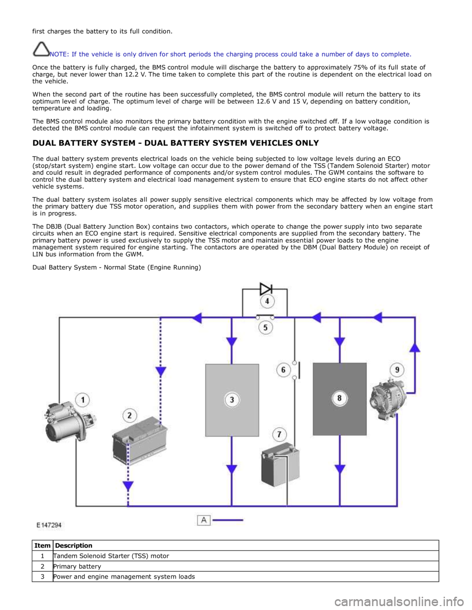
The DBJB (Dual Battery Junction Box) contains two contactors, which operate to change the power supply into two separate
circuits when an ECO engine start is required. Sensitive electrical components are supplied from the secondary battery. The
primary battery power is used exclusively to supply the TSS motor and maintain essential power loads to the engine
management system required for engine starting. The contactors are operated by the DBM (Dual Battery Module) on receipt of
LIN bus information from the GWM.
Dual Battery System - Normal State (Engine Running)
Item Description 1 Tandem Solenoid Starter (TSS) motor 2 Primary battery 3 Power and engine management system loads