Can bus JAGUAR XFR 2010 1.G Owners Manual
[x] Cancel search | Manufacturer: JAGUAR, Model Year: 2010, Model line: XFR, Model: JAGUAR XFR 2010 1.GPages: 3039, PDF Size: 58.49 MB
Page 1640 of 3039
Published: 29-Sep-2011
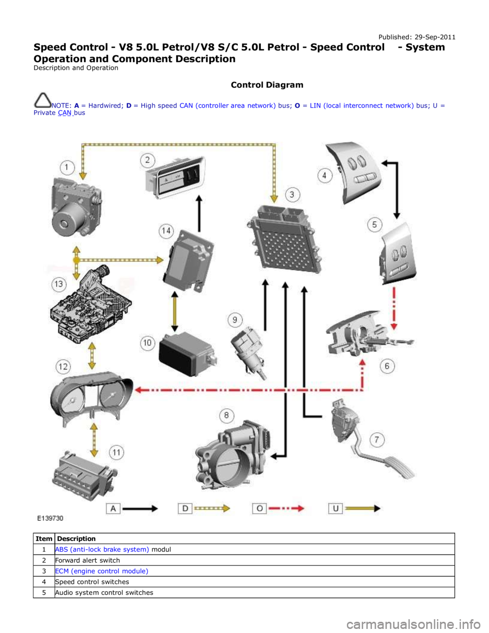
Speed Control - V8 5.0L Petrol/V8 S/C 5.0L Petrol - Speed Control - System
Operation and Component Description
Description and Operation
Control Diagram
NOTE: A = Hardwired; D = High speed CAN (controller area network) bus; O = LIN (local interconnect network) bus; U =
Private CAN bus
Item Description 1 ABS (anti-lock brake system) modul 2 Forward alert switch 3 ECM (engine control module) 4 Speed control switches 5 Audio system control switches
Page 1644 of 3039
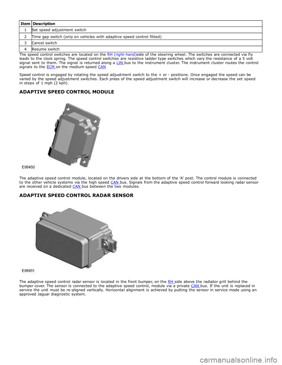
1 Set speed adjustment switch 2 Time gap switch (only on vehicles with adaptive speed control fitted) 3 Cancel switch 4 Resume switch The speed control switches are located on the RH (right-hand)side of the steering wheel. The switches are connected via fly
leads to the clock spring. The speed control switches are resistive ladder type switches which vary the resistance of a 5 volt
signal sent to them. The signal is returned along a LIN bus to the instrument cluster. The instrument cluster routes the control signals to the ECM on the medium speed CAN
Speed control is engaged by rotating the speed adjustment switch to the + or - positions. Once engaged the speed can be
varied by the speed adjustment switches. Each press of the speed adjustment switch will increase or decrease the set speed
in steps of 1 mph (2 kph).
ADAPTIVE SPEED CONTROL MODULE
The adaptive speed control module, located on the drivers side at the bottom of the 'A' post. The control module is connected
to the other vehicle systems via the high speed CAN bus. Signals from the adaptive speed control forward looking radar sensor are received on a dedicated CAN bus between the two modules.
ADAPTIVE SPEED CONTROL RADAR SENSOR
The adaptive speed control radar sensor is located in the front bumper, on the RH side above the radiator grill behind the bumper cover. The sensor is connected to the adaptive speed control, module via a private CAN bus. If the unit is replaced in service the unit must be re-aligned vertically. Horizontal alignment is achieved by putting the sensor in service mode using an
approved Jaguar diagnostic system.
Page 1645 of 3039

Item Description 1 Forward alert switch The forward alert system utilizes the adaptive speed control system components. Forward alert is turned on and off
independently of adaptive speed control, via a switch mounted in the lower outboard knee bolster switchpack. Forward alert
will notify the driver by means of a chime, a warning indicator in the instrument cluster and an indication in the message
center, when a target vehicle comes into range. The system will NOT use throttle or brake intervention to slow the vehicle.
The forward alert switch is connected to the instrument cluster in a resistive ladder with the luggage compartment opening
switch and the fuel filler flap switch. The instrument cluster sends the forward alert information to the Adaptive speed control
module on the CAN bus.
WARNING: The system is intended as a driver aid and should be used as such. The system is NOT a collision warning or
avoidance device.
The system sensitivity can be adjusted in the same manner as the adaptive speed control, via the steering wheel mounted
switches. Each adjustment is accompanied by a message in the message center. FORWARD ALERT SWITCHES
Page 1648 of 3039

DTC Description Possible Causes Action C1A67-98 Forward Looking Sensor
- Component or system
over temperature
Speed control sensor
internal temperature
exceeded threshold
Allow system to cool. Note: This DTC will be cleared
automatically when environmental conditions allow P174E-81
Output Shaft
Speed/ABS Wheel
Speed Correlation -
Invalid serial data
received
Follow speed is
mis-calculated to too
high a value
Clear DTC and re-test U0001-88
High Speed CAN
Communication Bus -
Bus off
Vehicle CAN Bus off
condition
Carry out any pinpoint tests associated with this
DTC using the manufacturer approved diagnostic
system. Carry out CAN network integrity tests using
the manufacturer approved diagnostic system U0100-00
Lost Communications
With ECM/PCM "A" - No
sub type information
ECM missing message
Carry out any pinpoint tests associated with this
DTC using the manufacturer approved diagnostic
system. Check ECM for related DTCs and refer to the
relevant DTC Index U0101-00
Lost Communications
With TCM - No sub
type information
TCM missing message
Carry out any pinpoint tests associated with this
DTC using the manufacturer approved diagnostic
system. Check TCM for related DTCs and refer to the
relevant DTC Index U0103-00
Lost Communication
With Gear Shift Control
Module A - No sub type
information
No sub type information
Refer to the electrical circuit diagrams and check the
power and ground connections to the Transmission
Shift Module. Using the manufacturer approved
diagnostic system, complete a CAN network integrity
test. Refer to the electrical circuit diagrams and
check the CAN network between the Transmission
Shift Module and Speed Control Module U0103-87
Lost Communication
With Gear Shift Module
- Missing Message
Transmission shift
module missing message
Carry out any pinpoint tests associated with this
DTC using the manufacturer approved diagnostic
system. Check transmission shift module for related
DTCs and refer to the relevant DTC Index U0121-00
Lost Communication
With Anti-lock Brake
System (ABS) Control
Module - No sub type
information
ABS missing message
Carry out any pinpoint tests associated with this
DTC using the manufacturer approved diagnostic
system. Check ABS for related DTCs and refer to the
relevant DTC Index U0128-00
Lost Communications
With Park Brake Module
- No sub type
information
Parking brake missing
message
Carry out any pinpoint tests associated with this
DTC using the manufacturer approved diagnostic
system. Check parking brake module for related
DTCs and refer to the relevant DTC Index U0155-00
Lost Communications
With Instrument Panel
Cluster (IPC) Control
Module - No sub type
information
Instrument cluster
missing message
Carry out any pinpoint tests associated with this
DTC using the manufacturer approved diagnostic
system. Check instrument cluster for related DTCs
and refer to the relevant DTC Index U0300-00
Internal Control Module
Software
Incompatibility - No
sub type information
Invalid configuration
message is received
Re-configure the speed control module using the
manufacturer approved diagnostic system. Clear
DTCs and re-test. If DTC still logged, suspect
incorrect speed control module installed. Check and
install a new module as required, refer to new
module/component installation note at top of DTC
Index U0300-55
Internal Control Module
Software
Incompatibility - Not
configured
RJB - at least one of the
car configuration
parameters is not
configured
Re-configure the RJB using the manufacturer
approved diagnostic system www.JagDocs.com
Page 1649 of 3039

DTC Description Possible Causes Action U0401-00
Invalid Data Received
From ECM/PCM A - No
sub type information
ECM did not respond
properly to speed control
cancel or auto brake
cancel request
Check ECM for related DTCs and refer to relevant
DTC Index U0401-67
Invalid Data Received
From ECM/PCM A -
Signal incorrect after
event
ECM did not respond
properly to speed control
resume request
Check ECM for related DTCs and refer to relevant
DTC Index U0401-81
Invalid Data Received
From ECM/PCM A -
Invalid serial data
received
Invalid data received
from engine control
module
Bus signal/message
failure
Speed control inhibited
by ECM
Check the Engine Control Module for related DTCs
and refer to relevant DTC Index. If U040181 is
logged as historic but no other DTCs have logged in
the engine control module at the same time and
distance, it may be caused by cranking with low
voltage conditions. Check battery and charging
system according to instructions in the battery care
manual. Install the latest Engine Control Module
software using the manufacturer approved diagnostic
system, contact Dealer Technical Support before
replacing components U0415-53
Invalid Data Received
From Anti-Lock Braking
System (ABS) Control
Module - De-activated
Event information
Deactivated
Check the Anti-Lock Braking System Module for
related DTCs and refer to the relevant DTC index U0415-81
Invalid Data Received
From Anti-lock Brake
System (ABS) Control
Module - Invalid serial
data received
Stability assist fault
Check ABS module for related DTCs and refer to
relevant DTC Index U0417-67
Invalid Data Received
From Park Brake
Control Module - Signal
incorrect after event
Parking brake module did
not respond properly to
apply request
Check parking brake module for related DTCs and
refer to relevant DTC Index U0417-81
Invalid Data Received
From Park Brake
Control Module -
Invalid serial data
received
Speed control inhibited
by parking brake module
Check parking brake module for related DTCs and
refer to relevant DTC Index U0418-68
Invalid Data Received
From Brake System
Control Module - Event
information
Event information
Check the Anti-Lock Braking System Module for
related DTCs and refer to the relevant DTC index U0421-81
Invalid Data Received
From Suspension
Control Module 'A' -
Invalid serial data
received
Invalid serial data
received
Check the Suspension Control Module for related
DTCs and refer to the relevant DTC index U0423-81
Invalid Data Received
From Instrument Panel
Control Module -
Invalid serial data
received
Speed control inhibited
by instrument cluster
Check instrument cluster, CJB and RJB for related
DTCs and refer to relevant DTC Index U1A00-88
Private Communication
Network - Bus off
Bus off
The module setting this code has disabled CAN
transmission. Check for other bus off codes. Check
the module and circuits. Refer to the electrical circuit
diagrams. Clear all DTCs and road test the vehicle. If
the concern reoccurs contact Dealer Technical
Support for further advice. Under no circumstance
should any parts be replaced to overcome this issue U1A14-49
CAN Initialisation
Failure - Internal
electronic failure
Internal electronic failure
Suspect the speed control module. Check and install
a new module as required, refer to the new
module/component installation note at the top of
the DTC Index U2101-00
Control Module
Configuration
Incompatible - No sub
type information
Data sent from RJB is
invalid
Check/amend Car Configuration File using the
manufacturer approved diagnostic system, clear DTC
and re-test. If DTC remains, re-configure RJB using
manufacturer approved diagnostic system, clear DTC
and re-test. If DTC remains check RJB for DTCs and
Page 1686 of 3039
Published: 11-May-2011
Climate Control - Air Distribution and Filtering - System Operation and
Component Description
Description and Operation
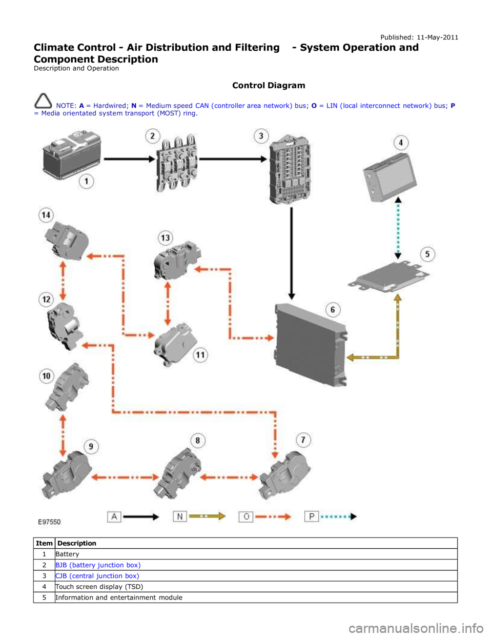
Control Diagram
NOTE: A = Hardwired; N = Medium speed CAN (controller area network) bus; O = LIN (local interconnect network) bus; P
= Media orientated system transport (MOST) ring.
Item Description 1 Battery 2 BJB (battery junction box) 3 CJB (central junction box) 4 Touch screen display (TSD) 5 Information and entertainment module
Page 1687 of 3039
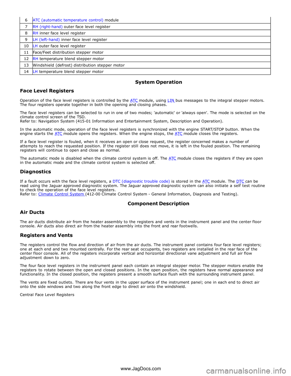
7 RH (right-hand) outer face level register 8 RH inner face level register 9 LH (left-hand) inner face level register 10 LH outer face level register 11 Face/Feet distribution stepper motor 12 RH temperature blend stepper motor 13 Windshield (defrost) distribution stepper motor 14 LH temperature blend stepper motor
Face Level Registers System Operation
Operation of the face level registers is controlled by the ATC module, using LIN bus messages to the integral stepper motors. The four registers operate together in both the opening and closing phases.
The face level registers can be selected to run in one of two modes; 'automatic' or 'always open'. The mode is selected on the
climate control screen of the TSD.
Refer to: Navigation System (415-01 Information and Entertainment System, Description and Operation).
In the automatic mode, operation of the face level registers is synchronized with the engine START/STOP button. When the
engine starts the ATC module opens the registers. When the engine stops, the ATC module closes the registers.
If a face level register is fouled, when it receives an open or close request, the register concerned makes a number of
attempts to reach the requested position. If the register still does not move, it is left in the fouled position. The remaining
registers will continue to open and close as normal.
The automatic mode is disabled when the climate control system is off. The ATC module closes the registers if they are open in the automatic mode and the climate control system is selected off.
Diagnostics
If a fault occurs with the face level registers, a DTC (diagnostic trouble code) is stored in the ATC module. The DTC can be read using the Jaguar approved diagnostic system. The Jaguar approved diagnostic system can also initiate a self test routine
to check the operation of the face level registers.
Refer to: Climate Control System (412-00 Climate Control System - General Information, Diagnosis and Testing).
Air Ducts Component Description
The air ducts distribute air from the heater assembly to the registers and vents in the instrument panel and the center floor
console. Air ducts also direct air from the heater assembly into the front and rear footwells.
Registers and Vents
The registers control the flow and direction of air from the air ducts. The instrument panel contains four face level registers;
one at each end and two mounted centrally. For the rear seat occupants, two registers are installed in the rear face of the
center floor console. All of the registers incorporate vertical and horizontal directional vane adjustment and full air flow
adjustment down to zero.
The four face level registers in the instrument panel each contain an integral stepper motor. The stepper motors enable the
registers to rotate between the open and closed positions. In the open position, the registers have normal appearance and
functionality. In the closed position, the registers present a smooth surface flush with the surrounding instrument panel.
The vents are fixed outlets. There are four vents in the upper surface of the instrument panel; one in each end to direct air
onto the side windows and two along the front edge to direct air onto the windshield.
Central Face Level Registers
www.JagDocs.com
Page 1692 of 3039
Published: 11-May-2011
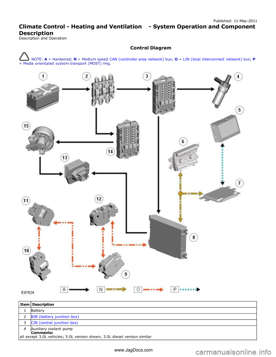
Climate Control - Heating and Ventilation - System Operation and Component Description
Description and Operation
Control Diagram
NOTE: A = Hardwired; N = Medium speed CAN (controller area network) bus; O = LIN (local interconnect network) bus; P
= Media orientated system transport (MOST) ring.
Item Description 1 Battery 2 BJB (battery junction box) 3 CJB (central junction box) 4 Auxiliary coolant pump Comments:
all except 3.0L vehicles; 5.0L version shown, 3.0L diesel version similar www.JagDocs.com
Page 1693 of 3039
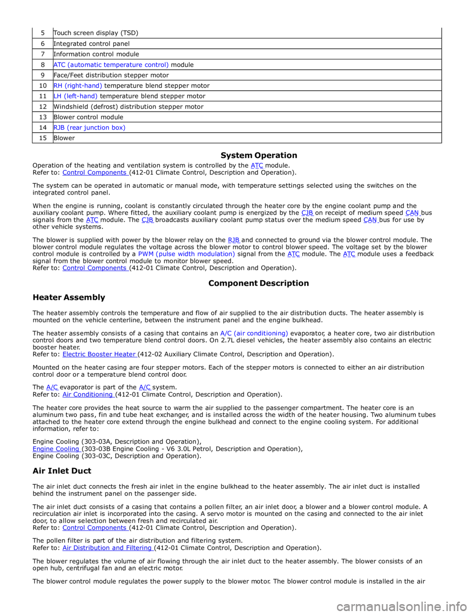
Touch screen display (TSD) 6 Integrated control panel 7 Information control module 8 ATC (automatic temperature control) module 9 Face/Feet distribution stepper motor 10 RH (right-hand) temperature blend stepper motor 11 LH (left-hand) temperature blend stepper motor 12 Windshield (defrost) distribution stepper motor 13 Blower control module 14 RJB (rear junction box) 15 Blower
System Operation
Operation of the heating and ventilation system is controlled by the ATC module. Refer to: Control Components (412-01 Climate Control, Description and Operation).
The system can be operated in automatic or manual mode, with temperature settings selected using the switches on the
integrated control panel.
When the engine is running, coolant is constantly circulated through the heater core by the engine coolant pump and the
auxiliary coolant pump. Where fitted, the auxiliary coolant pump is energized by the CJB on receipt of medium speed CAN bus signals from the ATC module. The CJB broadcasts auxiliary coolant pump status over the medium speed CAN bus for use by other vehicle systems.
The blower is supplied with power by the blower relay on the RJB and connected to ground via the blower control module. The blower control module regulates the voltage across the blower motor to control blower speed. The voltage set by the blower
control module is controlled by a PWM (pulse width modulation) signal from the ATC module. The ATC module uses a feedback signal from the blower control module to monitor blower speed.
Refer to: Control Components (412-01 Climate Control, Description and Operation).
Heater Assembly Component Description
The heater assembly controls the temperature and flow of air supplied to the air distribution ducts. The heater assembly is
mounted on the vehicle centerline, between the instrument panel and the engine bulkhead.
The heater assembly consists of a casing that contains an A/C (air conditioning) evaporator, a heater core, two air distribution
control doors and two temperature blend control doors. On 2.7L diesel vehicles, the heater assembly also contains an electric
booster heater.
Refer to: Electric Booster Heater (412-02 Auxiliary Climate Control, Description and Operation).
Mounted on the heater casing are four stepper motors. Each of the stepper motors is connected to either an air distribution
control door or a temperature blend control door.
The A/C evaporator is part of the A/C system. Refer to: Air Conditioning (412-01 Climate Control, Description and Operation).
The heater core provides the heat source to warm the air supplied to the passenger compartment. The heater core is an
aluminum two pass, fin and tube heat exchanger, and is installed across the width of the heater housing. Two aluminum tubes
attached to the heater core extend through the engine bulkhead and connect to the engine cooling system. For additional
information, refer to:
Engine Cooling (303-03A, Description and Operation),
Engine Cooling (303-03B Engine Cooling - V6 3.0L Petrol, Description and Operation), Engine Cooling (303-03C, Description and Operation).
Air Inlet Duct
The air inlet duct connects the fresh air inlet in the engine bulkhead to the heater assembly. The air inlet duct is installed
behind the instrument panel on the passenger side.
The air inlet duct consists of a casing that contains a pollen filter, an air inlet door, a blower and a blower control module. A
recirculation air inlet is incorporated into the casing. A servo motor is mounted on the casing and connected to the air inlet
door, to allow selection between fresh and recirculated air.
Refer to: Control Components (412-01 Climate Control, Description and Operation). The pollen filter is part of the air distribution and filtering system.
Refer to: Air Distribution and Filtering (412-01 Climate Control, Description and Operation).
The blower regulates the volume of air flowing through the air inlet duct to the heater assembly. The blower consists of an
open hub, centrifugal fan and an electric motor.
The blower control module regulates the power supply to the blower motor. The blower control module is installed in the air
Page 1708 of 3039
Published: 11-May-2011
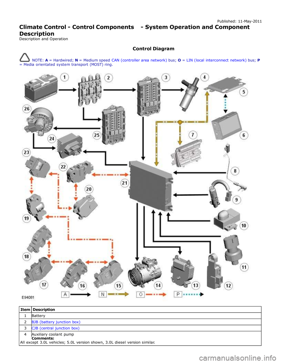
Climate Control - Control Components - System Operation and Component Description
Description and Operation
Control Diagram
NOTE: A = Hardwired; N = Medium speed CAN (controller area network) bus; O = LIN (local interconnect network) bus; P
= Media orientated system transport (MOST) ring.
Item Description 1 Battery 2 BJB (battery junction box) 3 CJB (central junction box) 4 Auxiliary coolant pump Comments:
All except 3.0L vehicles; 5.0L version shown, 3.0L diesel version similar.